1
MARINE TECHNOLOGIES, INC.
PROCEDURES TO TAKE DURING AN ALARM
! WARNING—THE ACTIVATION OF THIS DETECTOR INDICATES THE PRESENCE OF
DANGEROUS LEVELS OF GASOLINE OR PROPANE VAPORS THAT COULD CAUSE AN EXPLOSION
OR FIRE. TAKE THESE STEPS:
1) Turn off all electrical equipment, generators; extinguish open flames (oven, cook top, smoking materials
etc.).
2) Turn off the engine(s) if safe navigation conditions exist.
3) Open the engine compartment, ports, hatches and doors and ventilate the area.
4) If you are at shore, evacuate the boat. Do not return until the area is ventilated and the detector has
returned to normal standby condition.
5) Proceed with caution and locate and repair the cause of the leak. Seek a qualified technician if necessary.
6) Do not start or use the boat until the necessary repairs were made.
SPECIFICATIONS
Power Supply - 12 VDC
Operational Voltage - 7 to 15 VDC
Operating Temp -220 F - 1600 F
Alarm Threshold - <20% LEL of Gasoline and Propane
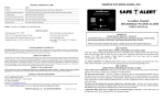
MARINE
GASOLINE AND PROPANE DETECTOR
USER’S MANUAL
IMPORTANT
PLEASE READ CAREFULLY AND SAVE
ATTENTION: This user’s manual contains important fume detector installation, operation,
troubleshooting and warranty information. Read, follow, and keep this manual for future reference.
Power Draw -.200 amps @ 14 VDC
NOTE: If you install or purchase this alarm for another person, give this manual to that person.
Other gases detected but not listed; Alcohol, Acetone, Hydrogen and most other flammable gases
!
Marine UL listed to Standard UL 1110
LIMITED PRODUCTS WARRANTY
MTI INDUSTRIES, INC. warrants to the original retail purchaser that its products will be free from defects of material or
workmanship for a period of One (1) year from the date of retail purchase. If proven to have been defective in original
materials or workmanship and returned, delivery costs prepaid, MTI INDUSTRIES, INC. will replace this product free of
charge.
LIMITS OF WARRANTY
Replacement is your exclusive remedy under this limited warranty or any other warranty (including any implied warranty of
merchantability for a particular purpose). Any and all implied warranties or merchantability or fitness for a particular
purpose shall be limited to the warranty period from the original date of retail purchase. MTI INDUSTRIES, INC., its
dealers and distributors shall in no case be responsible or in any way liable for any incidental or consequential damages for
any reason. Some states do not allow the limitation or exclusion of incidental or consequential damages, or allow limitations
on how long an implied warranty lasts, so the above limitations may not apply to you. This warranty gives you specific
rights, and you may also have other rights, which may vary, from state to state.
PRODUCT NOT WARRANTED
NOTE- There are no user serviceable parts inside the case. Opening any SAFE-T-ALERTTM product for any reason
voids the warranty. This warranty does not cover damage or failure resulting from acts of God, abuse, misuse, neglect, or
faulty installation.
WARRANTY RETURN PROCEDURES
It is MTI’s experience that an alarm is sounding for a reason. Call, ask your dealer to call, or e-mail our Customer Service
Department (as listed below) to trouble shoot the situation.
Customer Service Phone No. - 800-383-0269 Fax No. 847-546-9007
E-mail [email protected] Web Site: www.mtiindustries.com
If Customer Service determines that the unit is defective, a Replacement Authorization (RA) number will be issued. No
product will be accepted for service or replacement without first obtaining a RA number.
UL LISTED
SAFE-T-ALERT™ SA-1 and SA-1XL
R
©2004 MTI Industries, Inc. ALL RIGHTS RESERVED
MTI FORM NO: SA1-1004 Rev-1
WARNING
WHY EVERY BOAT NEEDS A FUME DETECTOR
Every year, boating injuries and deaths can be attributed to explosions that could have been avoided. Even fumes
from a half-cup of gasoline have the explosive force of six sticks of dynamite. With a boat’s gas-powered engine
or gas/LP gas powered appliances, vapors can easily develop in pumps, tanks, lines, or carburetors.
The SAFE-T-ALERT™ SA-1 and SA-1XL system is exclusively designed, tested and listed by the
Underwriters Laboratories for use in the harsh marine environment. The unit serves as an early warning detector
to protect you and your boat from propane and gas fumes. The SA-1 and SA-1XL provide sensors to detect the
build up of explosive gases even in early stages. The sensors alarm when 20% or less of the lower explosive
limit of gasoline or propane vapors is present in a monitored area.
! WARNING
LIMITATIONS OF FUME DETECTORS
This detector will not work without power. Some reasons your detector may not have power include an open circuit
breaker, a blown or missing fuse, a broken wire or improper wire crimp connection.
Detectors may not be heard. The detector’s loudness is designed to meet or exceed regulatory standards; however, the
detector may not be heard if they are remotely located. Individuals who are hard-of-hearing, have consumed alcoholic
beverages, have taken prescription, non-prescription or illegal drugs may not hear the alarm. If your boat has any
sleeping areas, consider installing additional detectors in those areas.
This detector will only indicate the presence of fumes at the sensor. The sensor cannot monitor a compartment that
is separated by a bulkhead. Gasoline fumes may be present in other areas. MTI recommends that sensors be installed in
ALL compartments containing fuel tanks and or engine(s) and compartments where gasoline or propane fumes may
accumulate.
INSTALLATION INSTRUCTIONS
Assemble the following supplies: An 3/8” electric drill, ¼” and 7/64” drill bits, 2-1/8” hole saw, electric
jigsaw, screwdrivers (Phillips and slotted), stainless-steel pan head screws, washers bolts, nuts, locking nuts,
silicone sealant, 18-, 14-gauge wire, inline fuse holder, 1A fuse, wire stripper, crimping tool, crimp connectors,
adhesive-lined heat shrink tubing, split loom wire wrap, heat gun, wire supports, and cable ties.
will turn off and the ON (GREEN) light will turn on. The detector is now operational and monitoring for
gas and propane fumes.
When you have the supplies on hand, take the following steps:
1. Locate the control panel at the helm where it can be easily seen and heard. Check first to be sure that there
is at least 3 inches of clearance behind the location to allow for mounting and wiring. Drill a 2 1/8 inch
hole and mount the control panel. Use a marine-grade silicone sealer if the unit is exposed to the weather.
DO NOT CONNECT POWER UNTIL THE INSTALLATION IS COMPLETE.
2. Connect the cable assembly to the control panel and run it to the engine compartment. Secure the run every
18 inches with plastic wire supports.
3. Locate the sensor in a dry area on a forward bulkhead in the engine compartment. The sensor should be at
the same height as the starter motor. Orient the sensor so that the 4-wire cable is facing down. This will
prevent any water or condensed water vapor from entering the unit. Connect the cable assembly from the
control panel to the sensor.
4. Connect a 1A inline fuse holder to the red (+) lead of the control panel. Run a length of red (+) 18-gauge
wire to the positive terminal on the 12V main battery. Run a length of 18-gauge yellow or black (-) wire to
the negative terminal on the 12V battery. Use ring-type insulated crimped connectors at the battery end of
the run. Secure the run every 18 inches with plastic wire supports. As added protection, use adhesive-lined
shrink tubing on all crimped connections.
5. Upon installation completion, run a system check of both the sensor and the control panel. Be sure to turn
the unit off when leaving the boat, as constant monitoring will run down the 12V battery.
WARNING: TEST THIS ALARM’S OPERATION AFTER THE BOAT HAS BEEN IN
STORAGE, BEFORE EACH TRIP, AND AT LEAST ONCE PER WEEK DURING USE.
1. With the unit on, check the sensor assembly light. The RED light should be on.
2. When the ON (GREEN) operation light is lit, the sensor assembly can be tested.
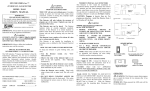
Your assembled system should look similar to the following.
5.
2.
When the sensor detects gasoline or propane fumes above the alarm threshold levels, the alarm will sound
and the ALARM (RED) light will turn on. The alarm will continue until the air in the monitored area
returns to safe levels. See the section on PROCEDURES TO TAKE DURING AN ALARM.
TESTING
!
!
3.
4.
WARNING: USE ONLY BUTANE LIGHTER TO PERFORM THIS TEST.
NEVER USE GAS SOAKED MATERIAL.
SENSOR TEST: Direct the lighter towards the sensor and depress the lever to release gas (only) into the sensor.
The alarm should sound and the ALARM (RED) light on the control panel should be lit.
SUPERVISORY CIRCUIT TEST 1: Disconnect one end of the 20-foot connector cable. The alarm should sound
and the ALARM (RED) light on the control panel should be lit.
SUPERVISORY CIRCUIT TEST 2: Use a rocking motion to pull the sensor (Figaro TGS 813) straight out from
the sensor assembly. The alarm should sound and the ALARM (RED) light on the control panel should be lit.
Power Supply 12vDC
Recommended Wire
Gauge 18 Ga.
IF THE UNIT DID NOT TEST PROPERLY, SEE THE TROUBLE SHOOTING GUIDE
!
WARNING: NEVER ENTER THE ENGINE COMPARTMENT WITH OPEN FLAME OR LIT
SMOKING MATERIALS. THEY CAN CAUSE EXPLOSION AND/OR FIRE.
MAINTENANCE
1.
2.
•
•
•
•
•
ADDITIONAL INSTALLATION TIPS
DO NOT mount the control panel under a cowling, or a glass or plastic panel where it my not be seen or
heard.
DO NOT locate the sensor above batteries. Hydrogen from the batteries may cause false alarms.
DO NOT locate the sensor behind an obstruction that will prevent air flow to the sensor.
DO NOT locate the sensor on the aft bulkhead. Water on the sensor will cause permanent damage to the
sensor and sensor assembly.
DO NOT locate the sensor within 12 inches of exhaust lines. High heat may cause false alarms.
OPERATION
The SA-1 and SA-1XL units have supervisory circuits to warn of a missing sensor, sensor assembly
malfunction, disconnected or a broken connector cable.
1.
Press the ON pad on the control panel. The WAIT (YELLOW) light should turn on. Press the TEST pad to
check the operation of the alarm sounder and alarm light. In about two minutes the WAIT (YELLOW) light
Keep the sensor free of dust and debris. It is recommended that the sensor—the Figaro TGS 813—(MTI Part No.
SA-186-S) be replaced annually due to the contamination caused in the marine environment. To replace, pull
sensor straight out from base.
Remove the sensor whenever the bilge compartment or engine compartment equipment is being cleaned, painted,
power washed etc. Direct contact with chemicals, WD-40, water, oil, etc. can cause permanent damage to the
sensor.
TROUBLE SHOOTING GUIDE
Problem
Cause
No Power
Wire connections, missing or blown fuse, reversed wires, or defective unit.
Locked In Wait
Replace sensor assembly SA-186-SB.
Immediate Alarm Turned On
Cable disconnected or broken, Sensor assembly, Check sensor assembly red light.
No Audible Alarm
Return for repair or replacement.
No Alarm During Supervision Tests
Return for repair or replacement.
Red LED ON Sensor Assembly Is Off
Unit is off, Cable disconnected or broken, SA-186-SB defective.
No Alarm when Sensor is Removed
If panel tests OK, replace the sensor Figaro TGS 813.
No Alarm With Lighter Test
If the panel tests OK, replace the Figaro TGS 813 sensor. If that does not remedy the condition, replace the sensor
assembly SA-186-SB.
NOTE: To order the Figaro TGS 813 sensor, specify MTI part number SA-186-S.