1
DRAG-SPORTSMAN
N2O
For
ELECTRONIC TRACTION
CONTROL
USER MANUAL
TELEPHONE 828.645.1505
FAX 828.645.1525
WWW.MORETRACTION.COM
US PATENT 6,577,944
Disclaimer……………….....................2
Introduction……………................... 3
How Does It Work………………………. 4
Installation………………................. 6
Testing……………………………............8
Sensor Test:…….........................................8
RPM Window Test:……………........................8
Forced Activation Test:…………….....…......9
Tuning………………………………..........11
Configuring……………......................14
Trigger Count: (default= 8)………………….14
Starting RPM: (default 1500 rpm)………...14
checking Settings …………………..……….… 16
Factory Reset ……….......................18
Appendix A…………….......................19
Ring & Sensor Installation............20
1
Davis Technologies TM-Drag-Sportsman-MAP V3 2010
DISCLAIMER
This product is sold "as is." No warranties express
or implied, including any implied warranty of
merchantability and any implied warranties of
fitness, are made with respect to any products
manufactured, sold or supplied by Davis
Technologies LLC ("DAVIS"). Davis shall not in any
event be liable for incidental, consequential or
punitive damages of any nature whatsoever,
including personal injury and lost profits. It is
acknowledged that participation in any motor sport
may result in serious injury or death, and that the
risk of such personal injury or death is assumed by
any person who uses any products manufactured,
sold or supplied by DAVIS.
2
Davis Technologies TM-Drag-Sportsman-MAP V3 2010
Introduction
We would first like to thank you for your purchase of
our system. We believe it is the best system
available to you on the market today. This system
balances effectiveness with ease of installation,
broad field of uses, and cost.
As with all technical devices such as engines,
shocks, carburetors, clutches etc., the product’s
performance is based largely on your ability to use it
properly. Testing in controlled circumstances will
help you determine the proper settings for your
application and your situation. Testing is very
important since it will help you utilize this product to
its full potential.
Please read all of the instructions and information
thoroughly before attempting to install or use this
product.
3
Davis Technologies TM-Drag-Sportsman-MAP V3 2010
How Does It Work?
This system differs from other systems that you may
be familiar with because it does not use any external
wheel or ground speed sensors. Instead it uses a
patented method that simply monitors engine speed
or driveline speed to determine when wheel spin
occurs. This process is a very simple way to
effectively detect wheel slippage and evoke a means
of correcting the slippage. In this case reducing the
Nitrous Injected degrades the engine performance.
When the Nitrous is reduced the loss of power is
instant and generally sufficient to stop or greatly
reduce the wheel spin.
However, there are limits to the unit. It is not a “FixAll.” It will not fix a bad tune up or poor driving. It
will however help a good driver in a good car get the
power to the ground better and make more full
passes. This allows the user to collect data to use to
determine how to make adjustment to the car to get
a better setup. A full pass, even if it is a few
hundredths slow is very valuable compared to
blowing the tires off 100 feet out.
For example, if your racecar experiences a loss of
traction around 300’ the system will detect this and
send a signal to the nitrous controller to reduce
nitrous. This will reduce the amount of torque
delivered to the drive wheels and help to regain grip
much faster than the driver can “pedal” the throttle.
With a little practice the system is easy to configure
and use. Typically after only a few test runs the
proper settings can be reached. Most drivers adapt
quickly to a car that does a little of the driving for
4
Davis Technologies TM-Drag-Sportsman-MAP V3 2010
them. The driver simply has to accept the fact that
the microprocessor in the system is much faster
than his/her reflexes. In fact the system detect
wheel spin in 1/100th of a second, and the
microprocessors used can process 5 million
commands a second!!
This system is not simply a few lines of code added
to an existing fuel injection or ignition system, and
called traction control.
This system utilizes a
patented method and multiple high speed
processors to very accurately and effectively
monitor rates of acceleration to determine wheel
speed, and tire slip. In fact, Davis Technologies’
systems are at least 20 times faster than other
systems which are integrated into the fuel injection
system.
Our systems only job is Traction Control !
5
Davis Technologies TM-Drag-Sportsman-MAP V3 2010
Installation
Installation of the system is very simple. It is very
important to make all connections correctly.
Improper installation could result in poor system
performance or damage to the unit.
Keep all wires away from any spark plug wires and
coils or other sources of electrical noise and heat.
The unit should be mounted away from any sources
of electrical noise or high heat. It can be easily
mounted using the mounting flanges on each side.
Make the connections as follows:
2 Pin Connector (power in)
1. Connect pin “A” (RED wire) to 12v positive.
2. Connect pin “B” (BLACK wire) to ground.
3 Pin Connector (Sensor)
1.
Connect the pin marked “A” (RED wire) to the
red wire on the sensor (12v positive)
2.
Connect the pin marked “B” (BLACK wire) to
the black wire on the sensor (ground).
3.
Connect the pin marked “C” (WHITE wire) to
the white wire on the sensor. This wiring is for
sensors supplied by Davis Technologies.
6
Davis Technologies TM-Drag-Sportsman-MAP V3 2010
If another type of sensor is used, check with the
manufacturer
to
determine
connections.
(IMPORTANT--The sensor must be capable of 15Khz
resolution!!)
3 Pin Connector (Input/Output)
1.
Connect the pin marked “A” (BLUE wire) to
the Trans Brake wire. (Coming from the trans brake
switch)
2.
Connect the pin marked “B” (YELLOW wire) to
the Nitrous Controller “Input 2” (RED wire).
3. Connect the pin marked “C” (PINK wire) to the
data system or a LED to indicate when the system is
making corrections. (12v+ output through a 1K
resistor)
This unit is designed specifically to
work with the Nitrous Express
Maximizer 3
7
Davis Technologies TM-Drag-Sportsman-MAP V3 2010
Testing
After installation it is recommended that you test the
system. To do so please follow these instructions
step by step. (Temporarily set the “% Cut” dial to
100 and “Ramp In” dial to 9 for testing)
Sensor test:
This test is useful for setting up the trigger ring and
sensor if used.
1.
Set the “Setup” dial to “0”
2.
Rotate the RPM trigger-
The LED will flash each time a trigger is sensed.
The unit is not active in any other way and no
corrections will be made. The LED will appear to
glow if triggered quickly. (The data output will also
trigger,
RPM Window Test:
This mode is useful to check that the system is
reading the RPM signal correctly. (To prevent the
progressive
controller
from
unintentionally
activating, the traction control’s Yellow wire should
be disconnected from the progressive controller).
1.
Set the “Setup” dial to “9”
2.
Start the engine and accelerate the driveline.
3.
When the driveline RPM is within the window
of 1000 to 3000 rpm the LED will glow solid
8
Davis Technologies TM-Drag-Sportsman-MAP V3 2010
and the unit will make a large correction.
Forced Activation Test:
This test is useful to check the cut function. The
progressive controller must be configured prior to
executing this test. (Activate the “Traction Control”
option in the progressive controller’s software, and
set the ramp to 100%, and uncheck the “RPM
Connected” box for this test). This is also useful to
test the connections to a data system if used.
1.
Set the “Setup” dial to any setting between 1
to 8.
2.
Turn “on” the power to the unit, the LED
should begin to flash.
3.
Arm the nitrous system, with the Fuel
and Nitrous systems de-pressurized !
(Close the bottle valve, disconnect the fuel
pump power, and purge both systems).
4.
With the engine off; activate the full throttle
switch and trans brake, if used, to start the
progressive
controller’s
cycle.
Quickly
press the Test button on the unit until
the LED glows solid.
The cut will activate for 4 seconds. (You will
hear the solenoids change sound as the
ramp is cut).
The data output wire (pink) will also be on for
the 4 seconds of the test.
Note: After the test is complete, the LED will blink to
show the firmware version.
9
Davis Technologies TM-Drag-Sportsman-MAP V3 2010
Note: Be sure to restore settings that were changed
in the controller software to race settings after
test is complete!
If unit does not pass all test, recheck all connections
and test again.
10
Davis Technologies TM-Drag-Sportsman-MAP V3 2010
Tuning
Rate Control Parameters:
Different tracks, cars, conditions, etc. may require
different settings for the system to function
effectively. The dial on the unit is used for this
setting. The values are referred to as Threshold.
The Drag-Sportsman incorporates a patented
method to control wheel spin where the users sets a
Threshold of acceleration that if exceeded will cause
the timing to retard.
The sensitivity of the system is adjusted using the
Threshold dial. The Threshold controls the
allowable percentage of acceleration allowed. The
higher the number the more sensitive the system is.
A good starting point is 4. Valid settings for
Threshold are 1-8. (0 turns unit off, except for sensor
test / 9 activates window RPM test).
The LED on the system is useful in determining the
settings. Once the driveline has crossed 1500 rpm
(default) for the first time the LED will flash when
the system is making a correction. If the unit seems
to be making too many corrections then the
Threshold setting may be too high. If the unit does
not seem to making enough corrections then the
Threshold may be set too low. Valid settings are 1
through 8. The higher the setting, the more sensitive the
traction control will be. A good starting point is 4.
11
Davis Technologies TM-Drag-Sportsman-MAP V3 2010
Starting RPM is a user adjustable setting that allows
the racer to set the point at which the unit Begins
making corrections. If the Starting RPM is set to
1800 RPM, then the unit is active and monitoring the
acceleration, but not making any corrections until
the Starting RPM is reached. This may be useful to
prevent the Traction Control from interfering with an
already established launch setup.
12
Davis Technologies TM-Drag-Sportsman-MAP V3 2010
Nitrous Control Parameters:
The % CUT is the setting that controls the amount of
the Nitrous Oxide that will be cut. This is the
percent of N20 on the stage that the progressive
controller is connected to only. The percent that the
stage is cut can be adjusted from 10% to 100%, in
10% increments.
Once the slip condition is
corrected, the N20 is ramped back in until the
original progressive ramp is re-established.
The RAMP IN is used to control how quickly the N20
is ramped back in after the slip condition is
corrected. The time is adjustable from 0/10th to
3/10th seconds in 10 steps. (3=1/10th second)
If the amount of power reduced during a slip
condition is too great, then a smaller % CUT may be
required. If the tires recover from a slip condition
and immediately slip again, then a longer RAMP IN
may be desired.
The light on the system is useful in determining the
settings. (A data acquisition system is preferred).
Once the driveline has crossed the Starting RPM
(default=1500 rpm) for the first time the light will
flash when the system is making a correction.
With testing and good record keeping, you should
be able to easily predict the necessary settings for
13
Davis Technologies TM-Drag-Sportsman-MAP V3 2010
current conditions. The settings will not vary much
once you determine what works best for your setup.
Configuring
Trigger Count:
(default= 8)
The unit must be configured for the number of
counts it will receive per revolution of the driveline.
Once set the value will remain until changed by the
user. To change the value, follow these steps.
1.
Set the “Setup” dial to “4”
2.
Hold down the “Test” button
3.
Turn the power On
4.
While holding the “Test” button down, move
the dial to the desired number of triggers divided by
two.
(example- 8 triggers/2=4)
5.
Release the “Test” button.
The LED will flash to show the number of triggers
the unit is now set to. (The Trigger Count must be
set correctly for the accurate RPM calculations)
Starting RPM: (default (15 ) 1500 Rpm)
Once set the value will remain until changed by the
user. The RPM is set in 100 rpm increments,
(example 1500 rpm, divided by 100 = 15). To change
the Starting RPM value, follow these steps.
1.
Set the “Setup” dial to “3”
14
Davis Technologies TM-Drag-Sportsman-MAP V3 2010
2.
Hold down the “Test” button
3.
Turn the power On
4.
While holding the “Test” button down, move
the “Setup” dial to the first digit of the desired
Starting RPM.
(example- 1500rpm - first digit=1 / 3000rpm - first digit =3)
5.
Release the “Test” button.
The led will flash to show the value has been
accepted.
6.
Now move the “Setup” dial to the second digit
of the desired Starting RPM, then press and release
the “Test” button. (example- 1500rpm - sec. digit=5 / 3000rpm sec. digit =0)
The led will flash to show the value has been
accepted.
After about 1 second the LED will Blink to show the
value that the Starting RPM is set to. The first digit
is output followed by a short pause, then the second
digit is output. (1500 RPM = 1,5 Blinks) (zeros are
indicated by shorter blinks)
15
Davis Technologies TM-Drag-Sportsman-MAP V3 2010
Checking Settings:
The current setting for the different adjustments can
be verified at any time using the Test button and the
LED.
This process is divided into 2 sections.
Standard, and Advanced. The different sections are
chosen by the position by the dial when the
verification is started.
The Standard values can be verified at any time by
following these steps.
1.
Turn the power “On”
2.
Set “Setup” dial any position from 1-7.
3.
Press the “Test” button and HOLD
DOWN.
4.
The LED will glow solid for 8
seconds (as in the Forced Activation Test),
then blink to show the firmware version.
5.
Next the LED will flash the value for the
Buffer. (A setting of zero is indicated by a
short blip of the LED).
6.
After a short pause, the Led will flash for the
value of Sample Rate, followed by a pause.
8.
Lastly, the LED will Flash the current Self
Learning status value.
(For tech support purposes only)
The Advanced values can be verified at any time by
following these steps.
16
Davis Technologies TM-Drag-Sportsman-MAP V3 2010
1.
Turn the power “On”
2.
Set “Setup” dial to “OFF”.
3.
Press the “Test” button and HOLD
DOWN.
4.
First, the value of the Starting RPM is
shown. The LED will blink for the first digit
followed by a short pause, then the LED will
blink for the second digit.(1500 RPM = 1,5
Blinks) (zeros are indicated by shorter
blinks).
5.
After a pause, The value for the Ending
RPM is shown. The LED will blink for the
first digit followed by a short pause, then
the LED will blink for the second digit.(8500
RPM = 8,5 Blinks) (zeros are indicated by
shorter blinks). (For tech support only)
6.
After a short pause, the LED will flash for the
value of Trigger Count. (8 Triggers=8 Blinks).
17
Davis Technologies TM-Drag-Sportsman-MAP V3 2010
Factory Reset
All settings can be restored to Factory Defaults at
any time by following these steps.
1.
Set the “Setup” dial to “5”
2.
Hold down the “Test” button
3.
Turn the power On
4.
While holding the “Test” button down, move
the “Setup” dial to the “Off“ position.
5.
Release the “Test” button,
The LED will flash rapidly to indicate the Factory
Settings have been restored.
18
Davis Technologies TM-Drag-Sportsman-MAP V3 2010
Appendix A
Another advantage of these systems is that they are
actually able to detect wheel slip better than most
wheel speed sensor based systems. The reason for
this is that our systems monitor the rotation of the
driveline. With 8 triggers on the driveline you can
measure slip within 1/8 of a rotation. Now factor in a
5:1 final drive (rear end) ratio and tire rotation can be
measured within 1/40 of a turn (that is about 2-3
inches on most tires). The fact that the driveline is
turning much faster than the wheels, amplifies the
slip at the driveline, making these systems much
more sensitive than the typical wheel speed
systems. Put simply, if the tires slip the driveline
revs. The only reason for the sudden increases in
revs in the driveline is wheel spin.
Sensor based systems usually measure tire rotation
about every 1/4 of a turn. The front and rear are
compared to each other to check for slip. With a
margin of error of 1/4 of a turn at each wheel, it may
take as much as 1/2 of a turn of tire slip for the
system to react. If a tire is allowed to slip a half a
turn before a correction is made, it is very hard to
stop the slip.
A system that uses a preset percentage of slip,
between the rear wheel speed to front wheel (or
ground) speed, cannot compensate for these
changing conditions that are inherent in all types of
racing.
19
Davis Technologies TM-Drag-Sportsman-MAP V3 2010
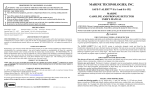
RING & SENSOR
If using a Davis Technologies Ring & Sensor, use the
following installation guidelines.
Sensor set to .065” gap on centerline
20
Davis Technologies TM-Drag-Sportsman-MAP V3 2010