1
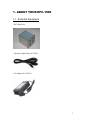
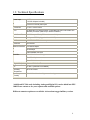
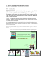
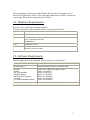
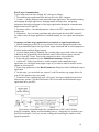
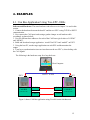
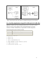
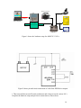
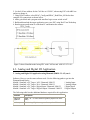
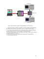
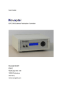
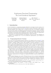
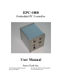
EPC-1000
Embedded PC Controller
User Manual
Servo Tech Inc
1747 W. Roosevelt Rd. Suite 110
Chicago, IL 60608
Ph: (312) 355-4853 Fax: (312) 355-2021
www.servotechinc.com
TABLE OF CONTENTS
1. About Your EPC-1000..………………………………………………………………..3
1.1. Equipment…………………………………………………………………….3
1.2. Technical Specifications……………………………………………………...4
1.3. Connection Ports and Cables…………………………………………………5
2. Installing Your EPC-1000...…………………………………………………………....6
2.1. Introduction…………………………………………………………………..6
2.2. Hardware Requirements……………………………………………………...7
2.3 Software Requirements……………………………………………………….7
3. Using Your EPC-1000...……………………………………………………………….8
3.1. Communication with Host PC……………………………………………….8
3.2. Setup………………………………………………………………………....8
3.3. System Test…………………………………………………………………..9
3.4. Creating an Executable Target/EPC Application…………………………...10
4. Examples…………………………………………………………………………..…..12
4.1. Application Using Two EPC-1000s with CAN Bus Card………………......12
4.2. Application Using EPC-1000 with CAN Bus Card and Cat ABL Box……..13
4.3. Analog and Digital I/O Application Using Diamond (DMM–32–AT) Card.15
5. Contact Information…………………………………………………………………...17
2
1. ABOUT YOUR EPC-1000
1.1. Included Equipment
-EPC Main Unit
-Cigarette Lighter Plug for 12VDC
-AC Adapter for 110VAC
3
1.2. Technical Specifications
Power Input
12VDC
(110VAC Adapter included)
2.0/5.5 mm Circular power jack
Dimensions
5.5 X 5.5 X 6.25 inches
CPU
On-board NS GX1-300 processor / Embedded low power NS Geode GX1300 MHz processor (Different cpu boards available.)
Solid State Disk
64 MB Compact Flash (Different sizes available)
RAM
64 Mbytes SDRAM (Upgradeable to 128 MB)
BIOS
AWARD 256 KB Flash memory
Serial Port
One RS-232
Ethernet Interface
Intel 82559 chipset
10/100 Mbps
RJ45 standard connector
CAN Bus
CAN-AC2-104 from Softing
Two D-Sub 9 pin connectors
10….1000 kbit/s transfer rate
*Digital I/O Option
Diamond DMM-32-AT
OS
PC Dos 7 (Different OS Available)
Operating
Temperature
-40 to 85 Celsius
Operating
Humidity
0% to 90% relative humidity, noncondensing
*Additional PC/104 cards including Analog and Digital I/O can be added into EPC1000. Please contact us for your requests and available options.
Different connector options are available. Ask us about rugged military version.
4
1.3. Connection Ports and Cables
Industrial Connectors
Military Connector Options
Power
Connector:
2.0/5.5mm jack, Military Bayonet 3p
Cable:
Cigarette Lighter Plug for 12VDC (incl.)
AC Adapter for 110VAC (incl.)
Ethernet
Connector:
RJ45
Cable:
Crossover between 2 PCs
UTP Network between PC and LAN
RS232
Connector:
1 2 3 4
5
6 7 8 9
1 2 3 4
5
D-Sub 9p, Military Bayonet 10p
Pin Lay Out: 1 –
2–
3–
4–
5–
6–
7–
8–
9–
-A
-B
-C
-D
-E
-F
-G
-H
-J
CAN
Connector:
D-Sub 9p, Military Bayonet 10p
Pin Lay Out: 2 –
5–
7–
6 7 8 9
Data Carrier Detect
Receive Data
Transmit Data
Data Terminal Ready
Ground
Data Set Ready
Request To Send
Clear To Send
Ring Indicator
CAN_Low
CAN_Shield
CAN_High
-B
-E
-G
2. INSTALLING YOUR EPC-1000
2.1. Introduction
EPC is a convenient device for Embedded Control Development System. It has GX1-300
MHz onboard processor with low power, fanless performance. The stable Geode
processor with onchip PCI VGA and Intel I82559ER high performance Ethernet chip
provide power and functionality. EPC also has a stacked CAN bus board with two CAN
cards. It has the provision for stacking additional I/O boards, which greatly enhances the
range of real-time applications.
The EPC is a solution for prototyping, testing, and deploying real-time systems using
standard PC hardware. It is an environment that uses an EPC, a host PC and a CAN bus
for running real-time applications.
A Typical fully operational EPC set up looks like below. It has an EPC with or without a
Host computer and a CAN Bus. Additional I/O boards can be stacked for customizing the
EPC for your local needs.
EPC is compatible with XPC Target software from Matlab. Matlab requires a valid user
license.
Figure shows a Hardware setup for Embedded Control Development System
Embedded PC
+Control Logic
Laptop PC
Software download, monitor, debug.
RS-232/USB/Ethernet (Development
ECM Programming Cable
CAN Bus
(Real time
control)
ECM
I/O Mapping
In this configuration, Electronic Control Module (ECM) acts as I/O mapping device
between I/O signals and CAN bus. EPC reads input signals from CAN bus, executes the
control logic and writes the output onto the CAN bus.
2.2. Hardware Requirements
Host PC can be a notebook or desktop computer.
The following table lists the minimum resources required on the host PC:
Hardware
Description
CPU
Pentium, Athlon or later
Peripherals
Hard disk drive with 60 Mbytes of free space
One 3.5-inch floppy disk drive
CD-ROM drive
RAM
128 Mbytes or more
Communication One free serial port (COM1 or COM2) with a 9-pin serial cable or an Ethernet
card with a cross over cable
2.3. Software Requirements
The following table lists the minimum software required on your host PC :
Software
Description
Operating system
Microsoft Windows XP (SP1) or Windows 2000
MATLAB
Simulink
Real-Time Workshop
Stateflow (optional)
State Flow Coder (optional)
xPC Target
xPC Target Embedded (optional)
Version 6.5.1.199709 (R13) Service Pack 1
Version 5.1(R13SP1)
Version 5.1(R13SP1)
Version 5.1.1(R13SP1)
Version 5.1.1(R13SP1)
Version 2.0.1(R13SP1)
Version 2.0.1(R13SP1)
C language compiler
Microsoft Visual C/C++ version 5.0 or higher
7
3. USING YOUR EPC-1000
3.1. Host PC Communication
RS-232 communication uses a null modem cable and COM ports of the host and target
PCs.
For TCP/IP communication, you must have a network adapter card correctly installed on
the host PC (EPC already has an onboard Ethernet adapter). Connect the host and target
computers with an unshielded twisted pair (UTP) cable to your local area network
(LAN). You can directly connect host and target PCs with a crossover cable.
3.2. Setup
EPC is set up for “Dosloader” mode by default.
At the Matlab command prompt, type >> xPCsetup
Then in EPC setup window as shown below, make the following selection:
CCompiler: VisualC
CompilerPath: C:\Program Files\Microsoft Visual Studio
CANLibrary: PC104
Target scope: Enabled
xPC target embedded option: “Dosloader“
For RS232, Select:
HostTarget com: RS232
RS232HostPort: COM1/COM2
(Pick default values)
(Pick default values)
RS232Baudrate: 115200
The recommended I/O base address for the CAN bus is“0X240
.
For
RS232
only
For TCP/IP
communication
only
8
Then, click the Update button to update system environment and the boot floppy button
in order to create the appropriate boot floppy disk.
3.3. System Test
In the MATLAB command prompt, type
>> xpctest
MATLAB runs the test script and displays messages indicating the success or failure of a
test. If you use RS232 communication, the first test is skipped.
>>###
>>###
>>###
>>###
>>###
>>###
>>###
>>###
>>###
>>###
>>###
xPC Target Test Suite 2.0.1
Host-Target interface is: TCP/IP (Ethernet)
Test 1, Ping target system using standard ping:... OK
Test 2, Ping target system using xpctargetping:... OK
Test 3, Reboot target using direct call: ....... OK
Test 4, Build and download xPC Target application: ... OK
Test 5, Check host-target communication for commands: .. OK
Test 6, Download xPC Target application using OOP: ... OK
Test 7, Execute xPC Target application for 0.2s: ... OK
Test 8, Upload logged data and compare with simulation:. OK
Test Suite successfully finished
Ping Target System xPC Target Ping test:
This test is an xPC Target ping to your target computer. If this test
fails, try troubleshooting with the following procedure:
At the MATLAB Command prompt, type:
>>tg = xpc
Check the messages in the MATLAB window. MATLAB should respond with the
following message.
xPC Object
Connected
Application
Mode
Status
CPUoverload
=
=
=
=
=
Yes
xpcosc
Real-Time Single-Tasking
stopped
none
At the Matlab command prompt, type:
>> Xpctargetping
Matlab displays the following message
ans =
success
If the connection is resumed (Connected = Yes), then the connection is all right. If the
connection is timing out consistently for a particular model, then the time out needs to be
increased. If all of the tests were successful, you are ready to build and download a target
application to the EPC.
3.4. Creating an Executable Target/EPC Application
9
Host-Target Communication:
Typical steps involved in developing xPC code are as follows:
1. Download a target application from the host PC to the EPC computer.
2. Control -- Change properties and control the target application. This includes starting
and stopping the target application, changing sample and stop times, and getting
information about the performance of the target application through the communication
link between host PC and EPC.
3. Parameter values -- Download parameter values to the EPC computer between runs or
during a run.
4. Signal data – Save real time signal data and upload signal data from EPC to host PC
for analysis after the target application is finished running, or view signal data during the
run.
Creating a real time target application for a loopback or signal acquisition test:
1. Before starting any model, in xpcsetup window, select the appropriate mode for the
xPC target embedded option, the type of host–target connection and its related properties.
Click the update and boot floppy buttons.
2. Create a simple model in Simulink, like a second order system with a Sin wave input.
Add blocks like gain and Mux from Simulink, and CAN bus blocks (setup, send and
receiver) from xPC Target. Then set the properties for these selected blocks.
3. Enter and select parameters in the Simulation Parameters dialog box.
4. Add an xPC Target Scope block to visualize signals while running the target
application, you can add as many target scopes as you want in order to monitor various
signals on your target PC.
5. Enter scope parameters in the Block Parameters dialog box before building the target
application.
6. At this stage, you can include any custom C code files and any xpc target drivers for
your PC/104 interfaces into your model.
7. From Real Time workshop tab, pick “xPC target” for target configuration and select
all necessary options. Click the Build button. This will create and download the target
application on to your EPC.
Figure shows a Simulink model for a loopback test on EPC with CAN bus
After the compiling, linking, and downloading process, a target object is created in your
MATLAB workspace. Now you can start, running and controlling the model to check
Signal Acquisition.
10
11
4. EXAMPLES
4.1. Can Bus Application Using Two EPC-1000s
Software and Hardware: The same hardware and software as in chapter 3 is used in this
section.
1. Connect the hardware between the host PC and the two EPC’s using TCP/IP or RS232
communication.
2. Now connect the CAN ports/cards using a gender changer or null modem cable
accordingly as shown below.
3. Use two different base addresses for each of the CAN buses (pick values of “0X240”
and “0X300”).
4. Build and download a target application “model1”on EPC1 and “model2” on EPC2.
5. Using the host PC, run the target application on each EPC and then monitor the
output.
6. Time lag or synchronization is not an issue between the two EPC’s, when dealing with
the CAN signals.
The following is the hardware setup for a loop back test.
Host Computer
RS232 / TCP/IP
EPC1
CAN-1
EPC2
CAN-1
CAN BUS
CAN BUS
(CAN-AC2-104)
(CAN-AC2-104)
CAN-2
CAN-2
Figure 1 shows CAN Bus application using Two EPC’s with CAN Bus card
12
model1
model2
Figure 2 shows Simulink model1 and model2 for a loopback test using two xpc’s with CAN bus
4.2. Can Bus Application Using EPC-1000 and CAT ABL Box
Software: In addition to the above-mentioned software tools, we also need Cat_utilites
toolboxes in order to run the ABL Box. RPAC (Rapid Prototyping for Automatic
Controls) is a Matlab / Simulink library to support ABL2CS in this configuration.
The following table lists the I/O hardware boards :
Hardware
Description
CAN BUS
CAN – AC2 – 104 from Softing
ABL Box
ABL2CS V3 from Caterpillar
PIN selection on ABL Box :
1. CAN_L(J1-6)
2. CAN_H(J1-18)
3. CAN_S(J1-19)
4. INPUT TO ABL/SWITCH6(J1-45)
5. INPUT TO ABL/SWITCH6(J2-56)
8. OUTPUT FROM ABL to bulb connector(+)(J2-64)
9. OUTPUT FROM ABL to bulb connector(-)(J2-52)
10. POWER TO ABL(+)(J2-70)
11. POWER TO ABL(-)(J2-69)
12. key switch for ABL Box (JI-58)
13
Power Converter
EPC
Switch
RS232
Host Computer
CAN-2
CAN BUS
CAN-1
Multimeter
CAN-AC2-104
ABL Box
Testing Lamp
Figure 1 shows the hardware setup for ABL2CS V3 I/O’s
Figure 2 shows pin and circuit connections of ABL Box PWM driver outputs
1. This test model has an on/off switch, multimeter and a lamp to test the various I/O’s.
Complete the hardware setup and pin/circuit connections as shown above.
14
2. Set the I/O base address for the CAN bus as “0X240”, when using EPC with ABL box
and never change it.
3. Using RPAC toolbox, select RPAC_Config and RPAC_ReadWrite_IO blocks then
complete I/O connections as shown below.
4. Add a gain block and a program with stateflow logic to turn switch on/off.
5. Build and download the target application on to your EPC using Real Time Workshop.
6. Run the target application by using host PC and monitor the outputs.
Figure 3 shows Simulink model using EPC with CAN bus and ABL2CS V3 I/O’s
4.3. Analog and Digital I/O Application
3. Analog and Digital I/O application using Diamond (DMM–32–AT) card :
Software: Here we use the same software tools. Use the following paths to get into the
Diamond board blocks,
Matlab / Simulink / xPC Target / A/D / Diamond / MM-32
// Analog Input
Matlab / Simulink / xPC Target / D/A / Diamond / MM-32
// Analog Output
Matlab / Simulink / xPC Target / Digital Input / Diamond / MM-32
// Digital Input
Matlab / Simulink / xPC Target / Digital Output / Diamond / MM-32 // Digital Output
The following table lists the additional hardware required for this application:
Hardware
Description
Analog I/O
Digital I/O
DMM – 32 – AT from Diamond systems (Optional on EPC1000)
Oscilloscope
2201 Analog / Digital storage oscilloscope from Tektronix
15
Oscilloscope
EPC
Digital I/O
DMM-32-AT
RS232
Host Computer
Analog I/O
Oscilloscope
Figure 1 shows hardware setup for Diamond(DMM-32-AT) board I/O’s
1. Connect the Laptop to the EPC using RS232 / TCP/IP communication and hook up
the Diamond board with the Oscilloscopes in order to complete hardware setup.
2. For real time implementations, remove all input and output components(Function
generator, Display, Scope, etc.) for the purpose of debug and analysis.
3. Provide I/O to Simulink blocks using “Input” and “Output” which will be connected
to Diamond (DMM-AT-32) board.
4. Build and download the target application using the above Diamond blocks.
5. Run and monitor the model.
16
5. CONTACT INFORMATION
For any questions, please contact us.
Address:
Servo Tech Inc
1747 W. Roosevelt Rd, Suite # 110
Chicago, IL, 60608
Phone:
Fax:
Web:
(312) 355-4853
(312) 355-2021
www.servotechinc.com
17