1
Section
Basic PC Operation and I/O Processes
1-2
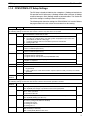
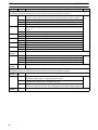
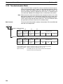
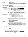
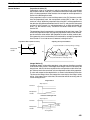
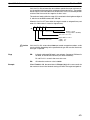
The cycle monitor time is used for checking for extremely long cycle times, as
can happen when the program goes into an infinite loop. If the cycle time exceeds the cycle monitor setting, a fatal error (FALS 9F) will be generated.
Note
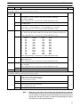
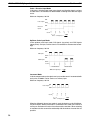
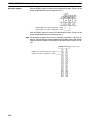
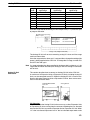
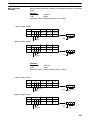
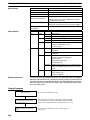
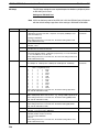
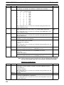
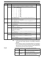
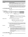
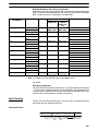
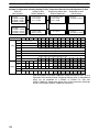
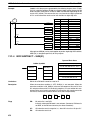
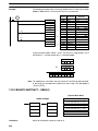
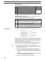
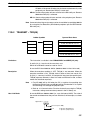
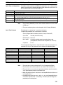
1. The units used for the maximum and current cycle times recorded in the AR
area (AR 14 and AR 15) are determined by the setting for the cycle monitor
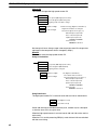
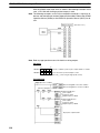
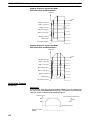
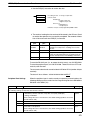
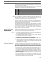
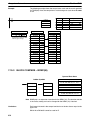
time in DM 6618, as shown below.
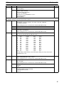
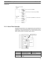
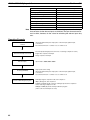
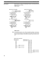
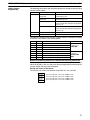
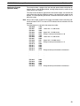
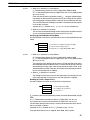
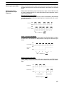
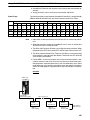
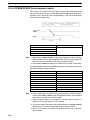
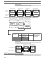
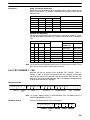
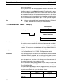
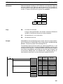
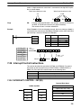
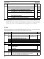
Bits 08 to 15 set to 01:
Bits 08 to 15 set to 02:
Bits 08 to 15 set to 03:
0.1 ms
1 ms
10 ms
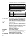
2. If the cycle time is 1 s or longer, the cycle time read from Programming Devices will be 999.9 ms. The correct maximum and current cycle times will be
recorded in the AR area.
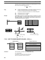
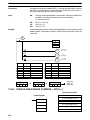
Example
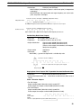
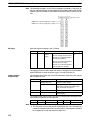
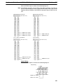
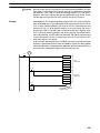
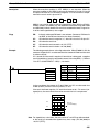
If 0230 is set in DM 6618, an FALS 9F error will not occur until the cycle time
exceeds 3 s. If the actual cycle time is 2.59 s, the current cycle time stored in the
AR area will be 2590 (ms), but the cycle time read from a Programming Device
will be 999.9 ms.
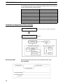
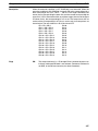
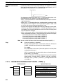
A “cycle time over” error (non-fatal) will be generated when the cycle time exceeds 100 ms unless detection of long cycle times is disable using the setting in
DM 6655.
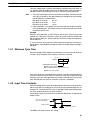
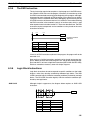
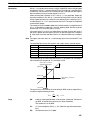
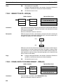
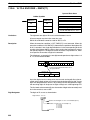
1-2-7 Minimum Cycle Time
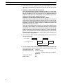
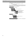
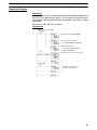
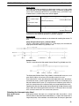
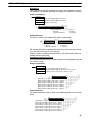
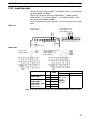
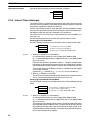
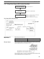
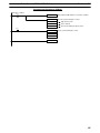
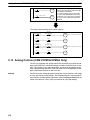
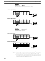
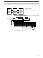
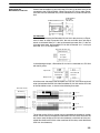
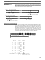
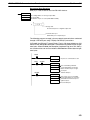
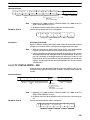
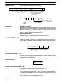
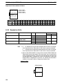
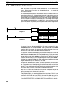
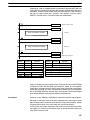
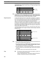
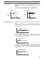
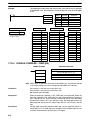
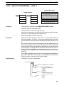
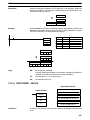
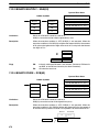
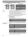
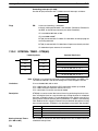
Make the settings shown below to standardize the cycle time and to eliminate
variations in I/O response time by setting a minimum cycle time.
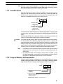
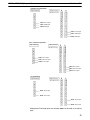
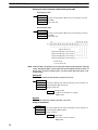
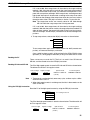
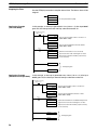
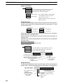
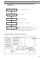
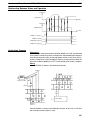
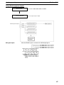
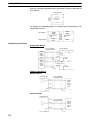
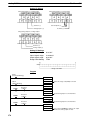
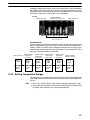
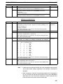
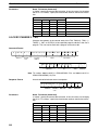
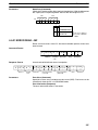
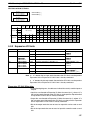
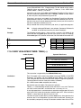
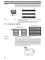
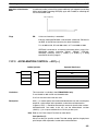
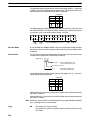
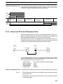
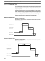
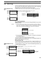
Bit 15
0
DM6619
Cycle time (4 digits BCD)
0000:Cycle time variable
0001 to 9999: Minimum cycle time (Unit: 1 ms)
Default: Cycle time variable
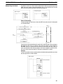
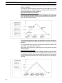
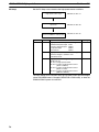
If the actual cycle time is shorter than the minimum cycle time, execution will wait
until the minimum time has expired. If the actual cycle time is longer than the
minimum cycle time, then operation will proceed according to the actual cycle
time. AR 2405 will turn ON if the minimum cycle time is exceeded.
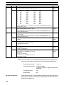
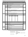
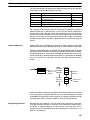
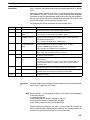
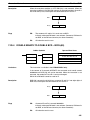
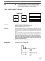
1-2-8 Input Time Constants
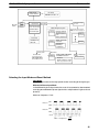
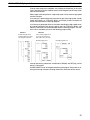
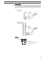
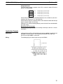
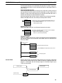
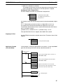
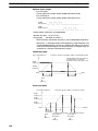
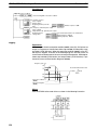
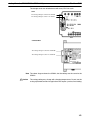
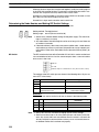
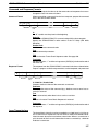
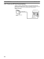
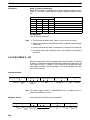
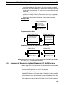
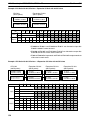
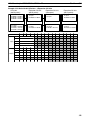
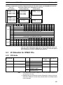
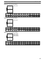
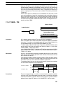
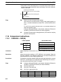
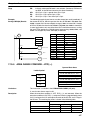
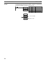
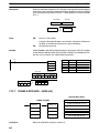
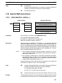
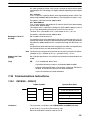
Make the settings shown below to set the time from when the actual inputs from
the DC Input Unit are turned ON or OFF until the corresponding input bits are
updated (i.e., until their ON/OFF status is changed). Make these settings when
you want to adjust the time until inputs stabilize.
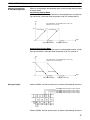
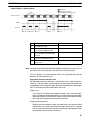
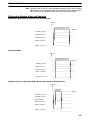
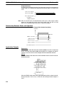
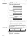
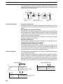
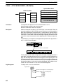
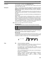
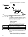
Increasing the input time constant can reduce the effects from chattering and
external noise.
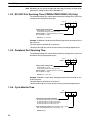
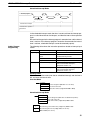
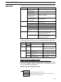
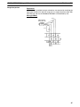
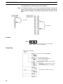
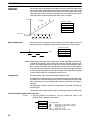
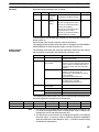
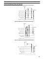
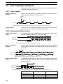
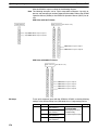
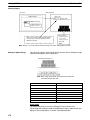
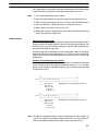
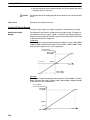
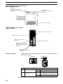
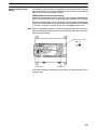
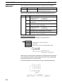
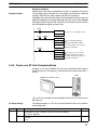
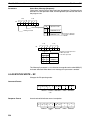
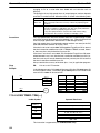
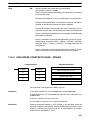
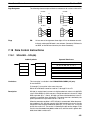
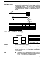
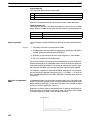
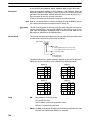
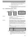
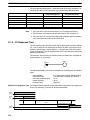
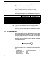
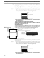
Input from an input device
such as a limit switch
Input bit status
t
t Input time constant
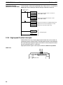
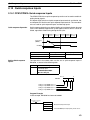
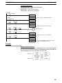
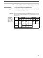
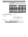
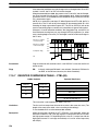
The SRM1(-V2) does not have this setting.
19