1
Section
Basic Ladder Diagrams
6-3
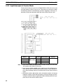
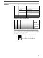
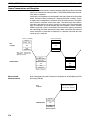
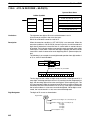
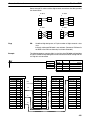
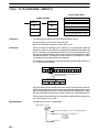
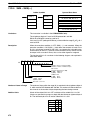
detail later) required for that instruction. Because some instructions require no
operands, while others require up to three operands, Program Memory addresses can be from one to four words long.
Program Memory addresses start at 00000 and run until the capacity of Program
Memory has been exhausted. The first word at each address defines the instruction. Any definers used by the instruction are also contained in the first word.
Also, if an instruction requires only a single bit operand (with no definer), the bit
operand is also programmed on the same line as the instruction. The rest of the
words required by an instruction contain the operands that specify what data is
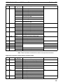
to be used. When converting to mnemonic code, all but ladder diagram instructions are written in the same form, one word to a line, just as they appear in the
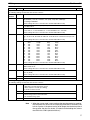
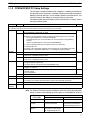
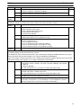
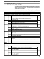
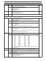
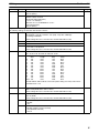
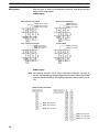
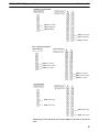
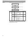
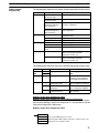
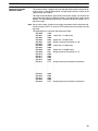
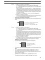
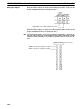
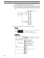
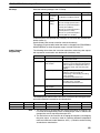
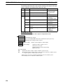
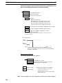
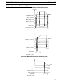
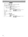
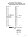
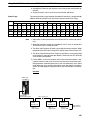
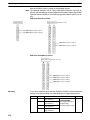
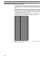
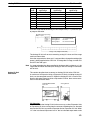
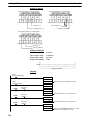
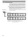
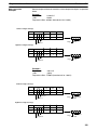
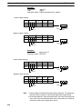
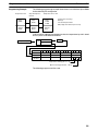
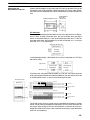
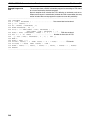
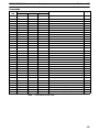
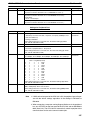
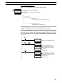
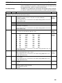
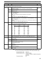
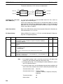
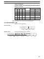
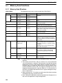
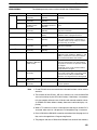
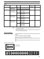
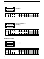
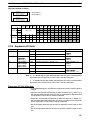
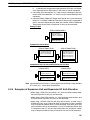
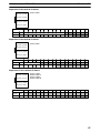
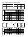
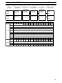
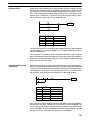
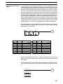
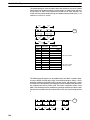
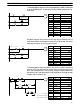
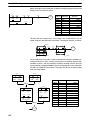
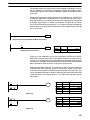
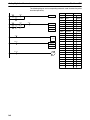
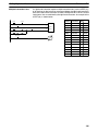
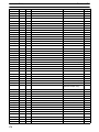
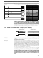
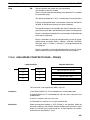
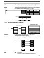
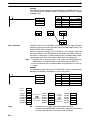
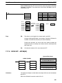
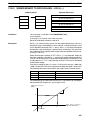
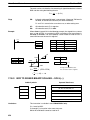
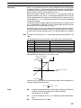
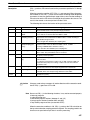
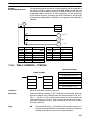
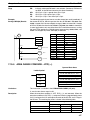
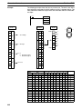
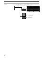
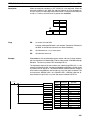
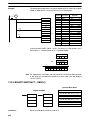
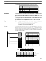
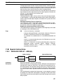
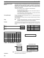
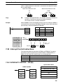
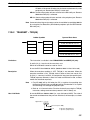
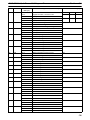
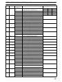
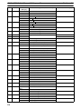
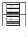
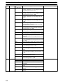
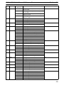
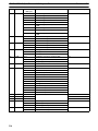
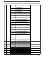
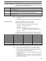
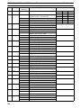
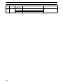
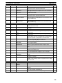
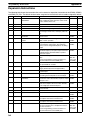
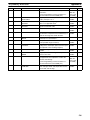
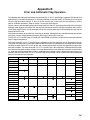
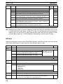
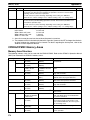
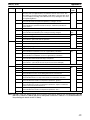
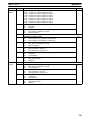
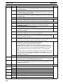
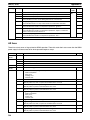
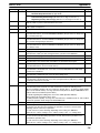
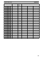
ladder diagram symbols. An example of mnemonic code is shown below. The
instructions used in it are described later in the manual.
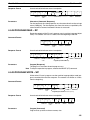
Address
Instruction
00000
00001
00002
00003
00004
00005
00006
LD
AND
OR
LD NOT
OR
AND LD
MOV(21)
Operands
HR
DM
00007
00008
00009
00010
00011
00012
00013
0001
00001
00002
00100
00101
000
0000
CMP(20)
DM
HR
0000
00
25505
20000
DM
DM
0000
0500
00502
00005
20001
AND
OUT
MOV(21)
LD
AND
OUT
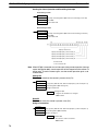
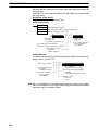
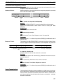
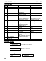
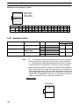
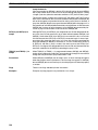
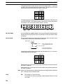
The address and instruction columns of the mnemonic code table are filled in for
the instruction word only. For all other lines, the left two columns are left blank. If
the instruction requires no definer or bit operand, the operand column is left
blank for first line. It is a good idea to cross through any blank data column
spaces (for all instruction words that do not require data) so that the data column
can be quickly scanned to see if any addresses have been left out.
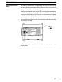
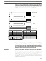
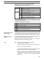
When programming, addresses are automatically displayed and do not have to
be input unless for some reason a different location is desired for the instruction.
When converting to mnemonic code, it is best to start at Program Memory address 00000 unless there is a specific reason for starting elsewhere.
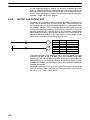
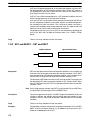
6-3-3
Ladder Instructions
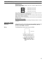
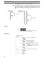
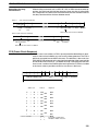
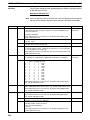
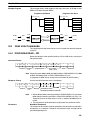
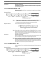
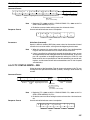
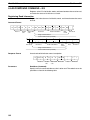
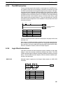
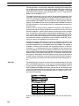
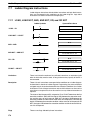
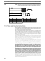
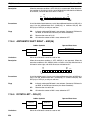
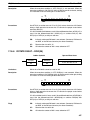
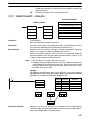
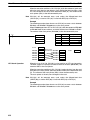
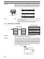
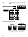
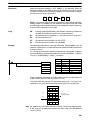
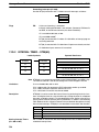
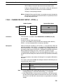
The ladder instructions are those instructions that correspond to the conditions
on the ladder diagram. Ladder instructions, either independently or in combination with the logic block instructions described next, form the execution conditions upon which the execution of all other instructions are based.
337