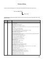
1
Section
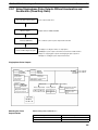
Basic Ladder Diagrams
6-3
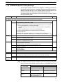
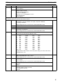
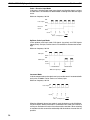
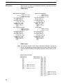
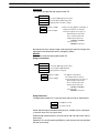
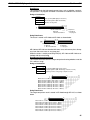
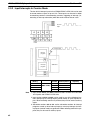
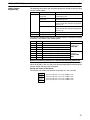
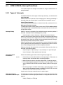
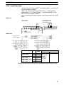
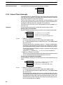
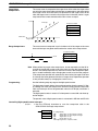
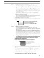
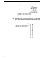
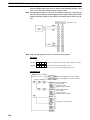
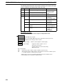
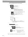
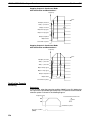
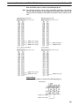
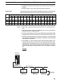
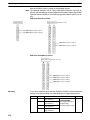
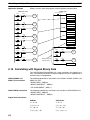
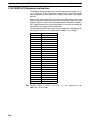
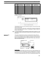
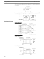
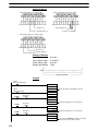
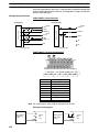
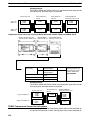
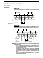
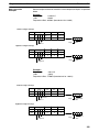
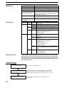
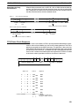
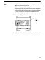
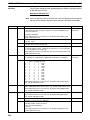
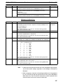
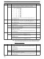
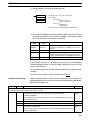
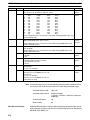
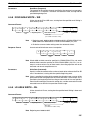
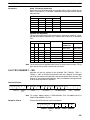
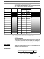
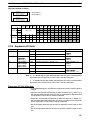
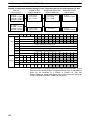
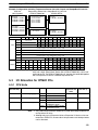
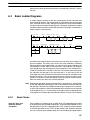
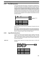
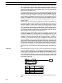
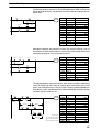
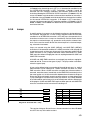
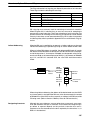
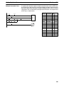
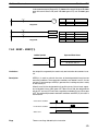
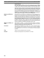
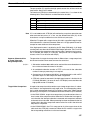
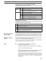
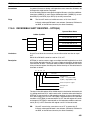
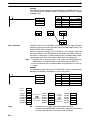
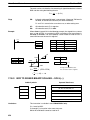
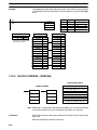
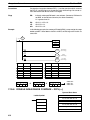
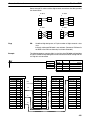
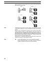
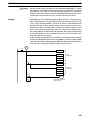
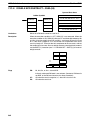
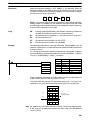
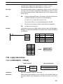
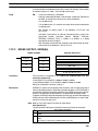
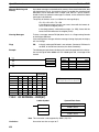
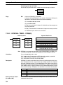
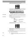
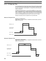
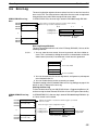
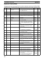
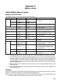
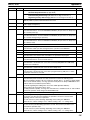
The first of each pair of conditions is converted to LOAD with the assigned bit
operand and then ANDed with the other condition. The first two blocks can be
coded first, followed by OR LOAD, the last block, and another OR LOAD, or the
three blocks can be coded first followed by two OR LOADs. The mnemonic code
for both methods is shown below.
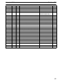
Address
Instruction
00000
00001
00002
00003
00004
00005
00006
00007
00008
LD
AND NOT
LD NOT
AND NOT
OR LD
LD
AND
OR LD
OUT
Operands
00000
00001
00002
00003
—
00004
00005
—
20001
Address
Instruction
00000
00001
00002
00003
00004
00005
00006
00007
00008
LD
AND NOT
LD NOT
AND NOT
LD
AND
OR LD
OR LD
OUT
Operands
00000
00001
00002
00003
00004
00005
—
—
20001
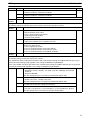
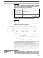
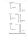
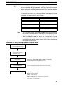
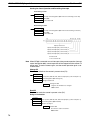
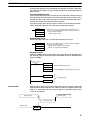
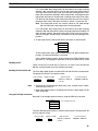
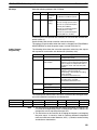
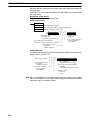
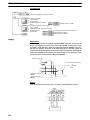
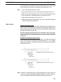
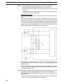
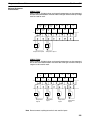
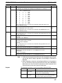
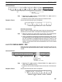
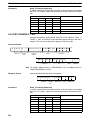
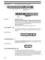
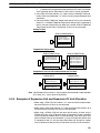
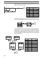
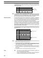
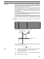
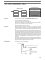
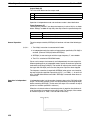
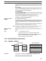
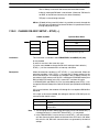
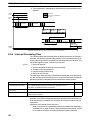
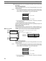
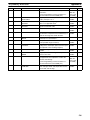
Again, with the method on the right, a maximum of eight blocks can be combined. There is no limit to the number of blocks that can be combined with the
first method.
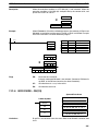
Combining AND LOAD and
OR LOAD
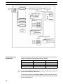
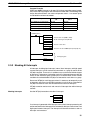
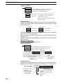
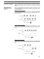
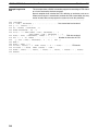
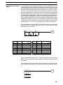
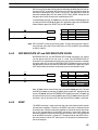
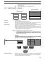
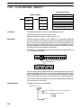
Both of the coding methods described above can also be used when using AND
LOAD and OR LOAD, as long as the number of blocks being combined does not
exceed eight.
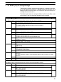
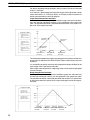
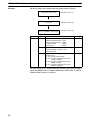
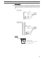
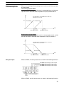
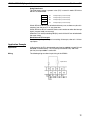
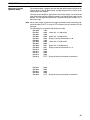
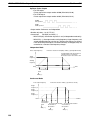
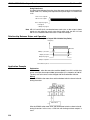
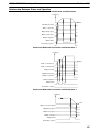
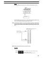
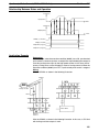
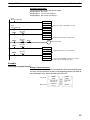
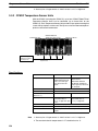
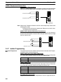
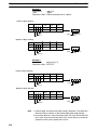
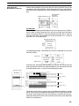
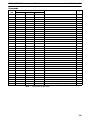
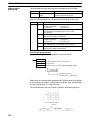
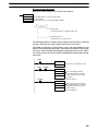
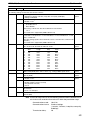
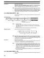
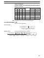
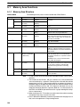
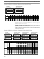
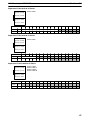
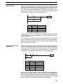
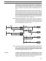
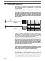
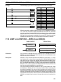
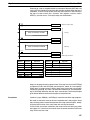
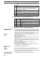
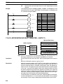
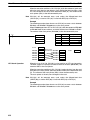
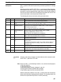
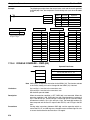
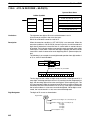
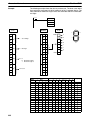
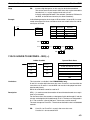
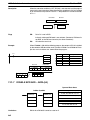
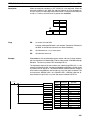
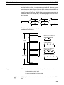
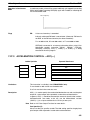
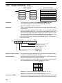
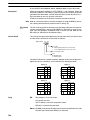
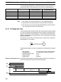
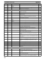
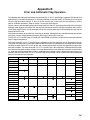
The following diagram contains only two logic blocks as shown. It is not necessary to further separate block b components, because it can coded directly using
only AND and OR.
00000 00001
00002 00003
20001
00201
00004
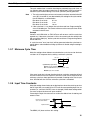
Block
a
Block
b
Address
Instruction
00000
00001
00002
00003
00004
00005
00006
00007
LD
AND NOT
LD
AND
OR
OR
AND LD
OUT
Operands
00000
00001
00002
00003
00201
00004
—
20001
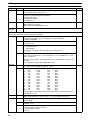
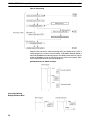
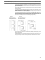
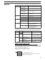
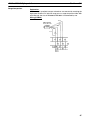
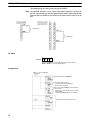
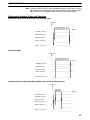
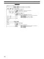
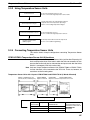
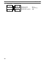
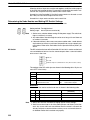
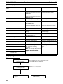
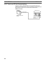
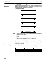
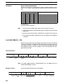
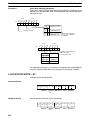
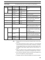
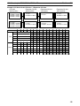
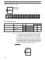
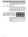
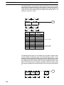
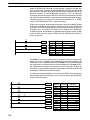
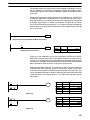
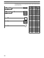
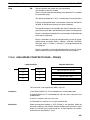
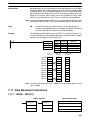
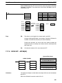
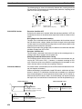
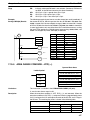
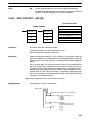
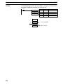
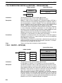
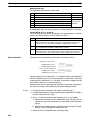
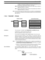
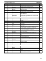
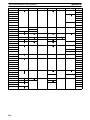
Although the following diagram is similar to the one above, block b in the diagram
below cannot be coded without separating it into two blocks combined with OR
LOAD. In this example, the three blocks have been coded first and then OR
LOAD has been used to combine the last two blocks followed by AND LOAD to
combine the execution condition produced by the OR LOAD with the execution
condition of block a.
344