1
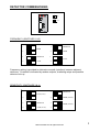
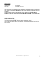
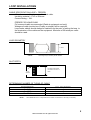
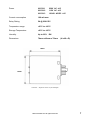
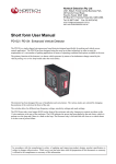
Single Channel Vehicle Detector
ULD 910
USER MANUAL
Part Number: MIC0302004
ULD 910
Hotron Ireland Ltd. All rights reserved
October
Revision:
2003
03
INDEX
PAGE
Detector Commissioning ............................................................................................................ 1
Frequency ........................................................................................................................... 1
Sensitivity ............................................................................................................................ 1
Automatic Sensitivity Boost (ASB) ...................................................................................... 2
Presence (Pres)................................................................................................................... 2
Pulse (Pulse) ....................................................................................................................... 2
Relay.................................................................................................................................... 3
Indications ...........................................................................................................................
Reset Push Button ............................................................................................................... 3
Pinouts........................................................................................................................................ 4
Loop installations ........................................................................................................................ 5
Cable Specification ............................................................................................................. 5
Loop Geometry ................................................................................................................... 5
Slot Depth ........................................................................................................................... 5
Determining Number of Turns of Cable .............................................................................. 5
Technical Specifications ............................................................................................................ 6
Hotron Ireland Ltd. All rights reserved
DETECTOR COMMISSIONING
OF
ON
FREQUENCY (SWITCHES 1 & 2)
1
1
MEDIUM
2
HIGH
HIGH
2
1
MEDIUM
1
LOW
2
LOW
2
2
Frequency setting is provided to eliminate crosstalk (interface) between adjacent
detectors. Crosstalk is indicated by random outputs, chattering relays and possible
detector lock-up.
SENSITIVITY (SWITCHES 3 & 4)
3
3
MEDIUM
4
HIGH (0.05%)
LOW (0.5%)
4
3
MEDIUM
3
HIGH (0.02%)
4
LOW (0.1%)
4
2
Hotron Ireland Ltd. All rights reserved
1
Sensitivity settings have been optimised to reliability produce an output at the required
change on inductance, or to ignore certain vehicle types if so required.
Typical inductance changes on a 2m x 1m (3 turns) loop:-
VEHICLE
∆L/L
BICYCLE
MOTORCYCLE
ARTICULATED TRUCK
SEDAN CAR
0.02 %
0.12 %
0.4 %
>1.0 %
AUTOMATIC SENSITIVITY BOOST (ASB) (SWITCH 5)
When ASB is selected (ON) the level of sensitivity is increased to HIGH after detection
has occurred. This ensures that Detection does not drop away under high-bed vehicles.
PRESENCE (PRES) (SWITCH 6)
ON OFF -
PERMANENT PRESENCE
LIMITED PRESENCE (1 hr for 3 % ∆L/L)
PULSE (PULSE) (SWITCH 7)
ON OFF -
PULSE ON UNDETECT (EXIT)
PULSE ON DETECT (ENTRY)
PULSE (RLY) (SWITCH 8)
ON
OFF -
2
RELAY 2
RELAY 2
PRESENCE
PULSE
Hotron Ireland Ltd. All rights reserved
INDICATIONS
GREEN LED
RED LED
-
POWER ON
CHANNEL OUTPUT
After initial power-up ort after a re-tune, the detector automatically tunes to the inductive
loop. After 0.2 seconds the RED LED will flash out the frequency of operation (50 kHz =
5 flashes)
If a fault condition exists on the loop (open circuit / short circuit) the RED LED will
FLASH at a fast rate. If a re-tune occurs the RED LED will FLASH, but at a slower rate.
RESET PUSH BUTTON
The Detector must be RESET whenever switch settings are altered.
Only a reset will clear the above fault indication conditions, providing the loop fault has
been cleared.
Hotron Ireland Ltd. All rights reserved
3
PINOUTS
6
5
7
4
8
3
9
2
10
1
11
**NOTE:- There are no Customer configurable settings internally.
PIN
1
2
3
4
5
6
7
8
9
10
11
4
DESCRIPTION
LIVE (DC+)
NEUTRAL (0V)
N / O RELAY 2
COMMON RELAY 2
N / O RELAY 1 (PRESENCE)
COMMON RELAY 1
(PRESENCE)
LOOP } TWIST THIS PAIR
LOOP } (20 TURNS PER
METRE)
EARTH
N / C RELAY 1
N / C RELAY 2
Hotron Ireland Ltd. All rights reserved
LOOP INSTALLATIONS
CABLE SPECIFICATION (LOOP + FEEDER)
1.5mm² cross sectional area, multi-strand cable.
Insulation material – PVC or Silicone.
Current Rating – 15A.
FEEDER FOR LONG RUNS
Foil screened cable recommended (Earth at equipment end only)
Waterproof cable junction box (Pratley or similar) will be required.
Loop feeder cables should always be twisted from the point of exiting the loop, to
the termination of the cables on the equipment. Minimum of 20 twists per metre
should be used.
LOOP GEOMETRY
1 metre
**NOTE:-
Avoid large loops, sensitivity will be affected.
SLOT DEPTH
30-50mm Dependent
on number of turns of
cable
Loop
Sealant
**NOTE:- Clean & dry slots prior to inserting cable.
DETERMINING NUMBER OF TURNS OF CABLE
PERIMETER
NO. OF TURNS
3–6M
6 – 10 M
10 – 30 M
4
3
2
**NOTE:-
Add 2 additional turns to compensate for the effects of sub-surface re-inforcing on sensitivity.
5
Hotron Ireland Ltd. All rights reserved
ULD 910 TECHNICAL SPECIFICATIONS
Tuning
Automatic
Inductive Range
20 – 1500uH
Sensitivity
Four steps adjustable
High 0.02% ∆L/L
Medium High 0.05% ∆L/L
Medium Low 0.1% ∆L/L
Low 0.1% ∆L/L
Sensitivity Boost
Selectable on :
Med High
Med Low
Low
Frequency
Four steps adjustable
Range: 20 – 140kHz
Response Time
App. 100ms (Turn on / Turn off)
Output Configuration
2 Output relays
Relay 1 – Presence (fail safe)
Relay 2 – Presence / Pulse (selectable)
Presence Time
Selectable – Permanent or Limited
(1hr for 3% ∆L/L)
Pulse Output Duration
150ms
(250 ms factory option)
Pulse Timing
Selectable – Permanent or limited
Indications
2 LEDs
Green – Power
Red – Output per channel
Reset push buttons
Flush mount on front panel
Protection
Loop Isolation
Transformer/zener diode/GDT
Power/Relays – MOV
6
Hotron Ireland Ltd. All rights reserved
Power
ULD 911
ULD 912
230V AC ±15
115V AC ±15
ULD 913
12/24V AC/DC ±15
Current consumption
100 mA max
Relay Rating
5A @ 230V DC
Temperature range
-40°C to +80°C
Storage Temperature
-40°C to +85°C
Humidity
Up to 95%
Dimensions
76mm x 40mm x 75mm
RH
(H x W x D)
75mm
76mm
Connector:
Single rear mount 11-pin submagnal
Hotron Ireland Ltd. All rights reserved
7