1
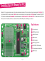
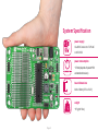
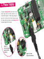
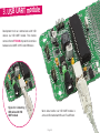
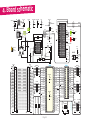
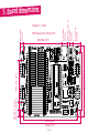
user's guide
Ready
to
for PIC
BOX edition
Best solution for fast and simple development of
applications using 28- and 40-pin PIC devices.
TO OUR VALUED CUSTOMERS
I want to express my thanks to you for being interested in our products and for having
confidence in Mikroelektronika.
The primary aim of our company is to design and produce high quality electronic products
and to constantly improve the performance thereof in order to better suit your needs.
Nebojsa Matic
General Manager
The Microchip, Atmel, NXP and CYPRESS name, logo and products names are trademarks of Microchip, Atmel, NXP and CYPRESS Inc. in the U.S.A. and other countries.
Page 2
Table of Contents
Introduction to Ready for PIC
4
Key features
4
System Specification
5
1. Power Supply
6
Voltage supply selector
7
2. Programming MCU
8
3. USB UART module
10
4. Board schematic
11
5. Board dimensions
12
Page 3
Introduction to Ready for PIC
Ready for PIC is a compact development tool for device development based on PIC microcontrollers. Board is equipped with PIC16F887 MCU
that is placed in DIP40 socket. Instead of DIP40 socket you can solder one for microcontrollers in DIP28 package. To program PIC16F887
MCU you can use preinstaled bootloader or external programmer (mikroProg for PIC, dsPIC and PIC32). For easy access to MCU pins
there are four 2x5 male headers that are marked with name of the MCU pin for which they are attached.
03
04
Key features
05
01 2x5 male header
06
01
02 PROTO board section
03 USB UART module
04 USB connector
07
05 AC/DC connector
02
06 Power supply selector
07 PIC16F887 in DIP40 socket
08 2x5 male header for mikroProg
09 RESET button
08
Page 4
09
System Specification
power supply
Via AC/DC connector 7-23V AC
or 9-32V DC
power consumption
~25mA (depends of placed MCU
and attached devices)
board dimensions
140 x 82mm (5.51 x 3.22“)
weight
~67g (0.15 lbs)
Page 5
1. Power Supply
To power up Ready for PIC board connect it with
power supply source via AC/DC connector or via
screw terminal, Figure 1-2. Power supply voltage can
vary from 7 to 23V AC or 9 to 32V DC. There’s no need
for voltage polarity orientation because Ready for PIC
has diode bridge rectifier on-board.
Figure 1-1:
Connecting power
supply via AC/DC
connector
Figure 1-2: Power
supply screw terminal
Page 6
Voltage supply selector
Place jumper in 5V
position in order to use
MCU that use 5V power
supply
Place jumper in 3.3V
position in order to use
MCU that use 3.3V power
supply
Figure 1-3: 5V power supply
Figure 1-4: 3.3V power supply
To use MCUs with different power supply voltages it is necessary to
place jumper marked with SUPPLY SELECT (J1) in correct position. If
you use MCU with a 5V power supply place jumper J1 in 5V position.
Otherwise, for 3.3V MCU place it in 3.3V position.
Page 7
2. Programming MCU
If you want to use external programer prior to bootloader on
PIC16F887 (or any other MCU) you need to make few adjustments.
First you need to cut copper between pads for the external
programmer, Figure 2-1. By doing so it will be made separation
between pins RB6, RB7, MCLR and VCC on MCU and from rest
of the board. After cut is made it’s time to solder the 2x5 male
header to the pads CN5, Figure 2-2. Now it’s time to place external
programer’s ICD10 connector on 2x5 male header, Figure 2-3. After
programming process is finished remove programer’s connector and
place jumpers over pins on 2x5 male header in order to use pins
RB6, RB7 and MCLR on rest of the board.
Figure 2-1: Make a cut before 2x5 header is placed
Figure 2-2: Solder 2x5 male header
Page 8
When soldering process is finished you can use external programer
(mikroProg for PIC, dsPIC, and PIC32) for MCU programing. To
place mikroProg’s IDC10 connector properly make sure that knob and
incision are placed towards inner side of the board, Figure 4-3.
Figure 2-3: Connecting
external programmer
Page 9
3. USB UART module
Development tool can communicate with USB
devices via USB UART module. This module
comes in form of FT232RL chip which is interface
between serial UART on MCU and USB device.
Figure 3-1: Connecting
USB cable with USB
UART module
When data transfer via USB UART module is
active a LEDs marked with Rx and Tx will flicker
Page 10
4. Board schematic
VIN
VCC-5V
E1
VCC-3.3
REG1
3
VOUT
2
E2
1
R2
2K2
MC33269DT3.3
10uF
VCC-FTDI
VCC-5V
VCC-FTDI
VCC
VCC-5V
C5
E3
C6
100nF
10uF
100nF
10uF
LD1
CN1
AC/DC
CN46
R10
USB B
0.22
CN2
FP1
FERRITE
VCC-USB
DD+
GND
VCC
USBDM
USBDP
C7
100nF
D4
J1
SWC
SWE
CT
GND
D5
330uF
VCC-5V
VCC
VCC-3.3
D2
4x1N4007
C9
D3
L1
220uH
DRVC
IPK
Vin
CMPR
E5
D6
MC34063A
220pF
R8
VCC-5V
330uF
MBRS140T3
R7
RC7-RX
0
TXD
DTR#
RTS#
VCCIO
RXD
RI#
GND
NC
DSR#
DCD#
CTS#
CBUS4
CBUS2
CBUS3
U2
E4
J2
U3
D1
MBRS140T3
VCC-FTDI
OSCO
OSCI
LD2
TEST
AGND
NC
RX-LED
LD3
CBUS0
TX-LED
CBUS1
GND
VCC-FTDI
VCC
RESET#
GND
3V3OUT
USBDM
USBDP
J3
R3
VCC
2K2
R4
VCC
2K2
VCC
R1
10K
RESET
MCLR
T1
C8
FT232RL
RC6-TX
0
C3
100nF
100nF
1K
VCC
PORTD
RD1
RD0
RD2
RD3
RD4
RD5
RD6
RD7
40 RB7-MCU
MCLR-MCU
1
28 RB7-MCU
2
39 RB6-MCU
RA0
2
27 RB6-MCU
RA1
3
38 RB5
RA1
3
26 RB5
RA2
4
37 RB4
RA2
4
25 RB4
RA3
5
36 RB3
RA3
5
24 RB3
35 RB2
RA4
6
23 RB2
34 RB1
RA5
7
22 RB1
8
21 RB0
9
20
OSC2 10
19
VCC-MCU
C10
RA4
6
RA5
7
RE0
8
33 RB0
RE1
9
32
RE2 10
31
VCC-MCU
100nF
11
VCC-MCU
12
CN39
VCC
OSC1 13
OSC2 14
R5
27
R6
27
C4
100nF
VCC-MCU
RC0 11
18 RC7-RX
RC1 12
17 RC6-TX
RC2 13
16 RC5-MCU
27 RD4
RC3-MCU 14
26 RC7-RX
25 RC6-TX
24 RC5-MCU
23 RC4-SDI
22 RD3
RD1 20
21 RD2
U1
Page 11
PORTC
VCC-MCU
28 RD5
RC2 17
RD0 19
CN37
29 RD6
RC1 16
PORTB
RB1
RB0
RB2
RB3
RB4
RB5
RB6
RB7
VCC
30 RD7
RC0 15
RC3-MCU 18
OSC1
RC1
RC3-SCK
RC5-SDO
RC7-RX
RC0
RC2
RC4-SDI
RC6-TX
CN38
VCC
15 RC4-SDI
U4
VCC
X1
11.0592MHz
C1
22pF
C2
22pF
mikroProg
CONNECTOR
VCC
1
RA0
OSC2
CN36
DIP28
DIP40
MCLR-MCU
OSC1
PORTA/E
RA1
RA0
RA2
RA3
RA4
RA5
RE0
RE1
RC3-SKC
RB0
RB1
RB2
RB3
RB4
RB5
RB6
RB7
RC0
RC1
RC2
RC3-SCK
RC4-SDI
RC5-SDO
RC6-TX
RC7-RX
MCLR
RB0
RB1
RB2
RB3
RB4
RB5
RB6
RB7
RC3-MCU
1
2
3
4
5
6
7
8
9
10
11
12
13
14
15
16
17
18
19
20
21
22
23
24
25
26
27
28
RC5-SDO
HDR1
1
2
3
4
5
6
7
8
9
10
11
12
13
14
15
16
17
18
19
20
21
22
23
24
25
26
27
28
RC5-MCU
HDR2
RA0
RA1
RA2
RA3
RA5
RE0
RE1
RE2
RD0
RD1
RD2
RD3
RD4
RD5
RD6
RD7
RA4
RD0
RD1
RD2
RD3
RD4
RD5
RD6
RD7
3K
VCC5
VCC-3.3
VCC-MCU
RB6
RB7
MCLR
RB6-MCU
RB7-MCU
MCLR-MCU
CN5
8.12mm 9mm
(0.32") (0.35")
66mm (2.59")
82mm (3.22")
48mm (1.89")
8.12mm
(0.32")
Tolerance +/- 0.3mm
PROTO area raster 2.54mm (0.10")
88.13mm (3.47")
124mm (4.88")
140mm (5.51")
Page 12
17.27mm
(0.68")
4.31mm (0.17")
9.14mm
(0.36")
12.95mm
(0.51")
5. Board dimensions
Notes:
Page 13
Notes:
Page 14
DISCLAIMER
All the products owned by MikroElektronika are protected by copyright law and international copyright treaty. Therefore, this manual is to be treated as any
other copyright material. No part of this manual, including product and software described herein, may be reproduced, stored in a retrieval system, translated or
transmitted in any form or by any means, without the prior written permission of MikroElektronika. The manual PDF edition can be printed for private or local
use, but not for distribution. Any modification of this manual is prohibited.
MikroElektronika provides this manual ‘as is’ without warranty of any kind, either expressed or implied, including, but not limited to, the implied warranties or
conditions of merchantability or fitness for a particular purpose.
MikroElektronika shall assume no responsibility or liability for any errors, omissions and inaccuracies that may appear in this manual. In no event shall MikroElektronika, its directors, officers, employees or distributors be liable for any indirect, specific, incidental or consequential damages (including damages for
loss of business profits and business information, business interruption or any other pecuniary loss) arising out of the use of this manual or product, even if
MikroElektronika has been advised of the possibility of such damages. MikroElektronika reserves the right to change information contained in this manual at
any time without prior notice, if necessary.
HIGH RISK ACTIVITIES
The products of MikroElektronika are not fault – tolerant nor designed, manufactured or intended for use or resale as on – line control equipment in hazardous
environments requiring fail – safe performance, such as in the operation of nuclear facilities, aircraft navigation or communication systems, air traffic control, direct life support machines or weapons systems in which the failure of Software could lead directly to death, personal injury or severe physical or environmental
damage (‘High Risk Activities’). MikroElektronika and its suppliers specifically disclaim any expressed or implied warranty of fitness for High Risk Activities.
TRADEMARKS
The Mikroelektronika name and logo, the Mikroelektronika logo, mikroC, mikroC PRO, mikroBasic, mikroBasic PRO, mikroPascal, mikroPascal PRO, AVRflash,
PICflash, dsPICprog, 18FJprog, PSOCprog, AVRprog, 8051prog, ARMflash, EasyPIC5, EasyPIC6, BigPIC5, BigPIC6, dsPIC PRO4, Easy8051B, EasyARM, EasyAVR5,
EasyAVR6, BigAVR2, EasydsPIC4A, EasyPSoC4, EasyAVR Stamp LV18FJ, LV24-33A, LV32MX, PIC32MX4 MultiMedia Board, PICPLC16, PICPLC8 PICPLC4,
SmartGSM/GPRS, UNI-DS are trademarks of Mikroelektronika. All other trademarks mentioned herein are property of their respective companies.
All other product and corporate names appearing in this manual may or may not be registered trademarks or copyrights of their respective companies, and are
only used for identification or explanation and to the owners’ benefit, with no intent to infringe.
© Mikroelektronika™, 2011, All Rights Reserved.
Page 15
Ready
for PIC
BOX edition
If you want to learn more about our products, please visit our website at www.mikroe.com
If you are experiencing some problems with any of our products or just need additional
information, please place your ticket at www.mikroe.com/en/support
If you have any questions, comments or business proposals,
do not hesitate to contact us at [email protected]