1
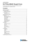
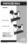
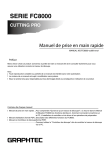
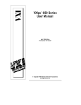
INSTALLATION GUIDE
NI VXIpc -882
™
This guide contains information about installing and troubleshooting your
NI VXIpc-882 controller and components. This guide refers to the
NI VXIpc-882 User Manual, which you should have received in either
hardcopy or PDF format with your VXI controller. The PDF version of this
manual is also available online at ni.com/support.
Electrostatic discharge can damage your controller. To avoid such damage,
handle the controller only in a proper ESD-controlled environment.
Caution
Installing the NI VXIpc-882
This section contains general installation instructions for the
NI VXIpc-882 controller. Consult your VXIbus chassis user manual or
technical reference manual for specific instructions and warnings.
1.
Plug in your chassis before installing the controller. The power cord
grounds the chassis and protects it from electrical damage while you
are installing the controller.
To protect both yourself and the chassis from electrical hazards, the chassis
should remain off until you finish installing the controller.
Caution
2.
Remove or open any doors or covers blocking access to the chassis
slots.
If the controller is not configured for automatic System Controller detection, be
certain that the slot you select in your VXIbus chassis matches the controller configuration
as either a System Controller device or a Non-System Controller device. Installing the
controller into a slot that does not correspond with the jumper setting can damage the
controller, the VXIbus backplane, or both. See the NI VXIpc-882 User Manual for jumper
configuration information.
Caution
3.
Insert the controller in the desired slot by aligning the top and bottom
of the controller with the card-edge guides inside the chassis. Slowly
push the controller straight into the slot until its plug connectors are
resting on the backplane receptacle connectors. Using slow, evenly
distributed pressure, press the module straight in until it seats in the
expansion slot. The front panel of the controller should be even with
the front panel of the chassis.
4.
Tighten the retaining screws on the top and bottom edges of the front
panel.
5.
Check the installation.
6.
Connect the keyboard and mouse to the USB connectors.
Install a noise-suppression ferrite (included in your shipping kit) onto the external
USB cable when using a USB mouse or keyboard to ensure that your device meets all EMC
standards applicable to your country. For more information on installing the ferrite, refer
to KnowledgeBase 4Q0899P6 at ni.com.
Note
7.
Connect the DVI-I monitor video cable to the DVI-I connector.
8.
Connect devices to ports as required by your system configuration.
9.
Replace or close any doors or covers on the chassis.
10. Power on the chassis.
11. The controller should now boot. If the controller does not boot, see
What if the NI VXIpc-882 does not boot? in the Troubleshooting
section.
12. On the first boot of the controller, a setup program automatically runs.
13. Follow the prompts in the setup program to fully configure your
controller.
14. When prompted for the Windows serial number, enter the serial
number of the operating system from the included certificate.
15. Your controller is now ready for development.
NI VXIpc-882 Installation Guide
2
ni.com
Figure 1 shows an NI VXIpc-882 installed in the system controller slot of
a National Instruments VXI chassis. You can place VXI devices in any
other slot.
1
2
1
NI VXIpc-882 Controller
2
VXI Chassis
Figure 1. NI VXIpc-882 Controller Installed in a VXI Chassis
How to Remove the Controller from the VXI Chassis
The NI VXIpc-882 controllers are designed for easy handling. To remove
the controller from the VXI chassis, complete the following steps:
1.
Shut down all applications and the operating system.
2.
Turn off power.
3.
Disconnect devices from the front panel ports as your system
configuration requires.
4.
Remove the retaining screws in the controller front panel.
5.
Push the upper ejector handle up and the lower ejector handle down
until the controller pops out of the backplane connectors.
6.
Slide the controller out of the chassis.
© National Instruments Corporation
3
NI VXIpc-882 Installation Guide
Removing the NI VXIpc-882 Component Side Cover
The NI VXIpc-882 is housed in a metal enclosure comprised of a
component-side (top), solder-side (bottom), and rear cover to improve
EMC performance and provide easy handling. Remove the component side
cover to access the jumper settings.
Complete the following steps to remove the top and rear covers from the
controller.
1.
Remove the three Phillips-head screws attaching the rear cover to the
component-side cover.
2.
Remove the eight screws holding the component-side cover to the
solder side cover, and the two screws holding the component-side
cover to the module standoffs.
3.
Lift the component-side and rear covers away from the module.
Installing and Upgrading RAM
The NI VXIpc-882 uses PC2 5300 DDR2 SDRAM and supports up to 2 GB
in each of the two RAM sockets.
National Instruments recommends the following size SO-DIMMs for use
with the NI VXIpc-882 controller (SDRAM):
•
PC2-5300 1 GB, 128 MB × 64, CL 5, 1.18 in. max
(NI part number 779302-1024)
•
PC2-5300 2 GB, 256 MB × 64, CL 5, 1.18 in. max
(NI part number 780031-2048)
Note National Instruments has tested and verified that the DDR2 SO-DIMMs we sell
work with the NI VXIpc-882. We recommend you purchase your DDR2 SO-DIMM
modules from National Instruments. Other off-the-shelf DDR2 SO-DIMM modules
are not guaranteed to work properly.
To add or replace RAM for the NI VXIpc-882, complete the following
steps:
NI VXIpc-882 Installation Guide
1.
Remove the NI VXIpc-882 from the chassis. See the removal
instructions in the How to Remove the Controller from the VXI Chassis
section.
2.
Remove the component side cover. Refer to the removal instructions in
the Removing the NI VXIpc-882 Component Side Cover section.
3.
Add the SO-DIMM modules to the empty SO-DIMM sockets.
See Figure 2.
4
ni.com
To optimize both memory capacity and system performance, use the same size and
speed memory module in each of the two module slots. The use of different size modules
in each slot is supported, but system performance will be slower than using two matched
modules. However, two mismatched modules will result in better performance than using
a single module.
Note
3
2
1
1
SO-DIMM Socket XA1
2
SO-DIMM Module
3
SO-DIMM Socket XA2
Figure 2. Installing a SO-DIMM in an NI VXIpc-882 Controller
Installing and Removing the Internal Hard Drive
Follow these steps to remove the internal hard drive from your
NI VXIpc-882 controller:
1.
Remove the controller from the chassis. See the removal instructions
in the How to Remove the Controller from the VXI Chassis section.
2.
Remove the component side cover. See the removal instructions in the
Removing the NI VXIpc-882 Component Side Cover section.
3.
Remove the four screws under the solder side cover that hold the
hard drive in place. You will need a 2 mm hex driver to remove the
M3 button head screws.
© National Instruments Corporation
5
NI VXIpc-882 Installation Guide
Be careful when sliding the hard drive toward the bottom of the controller. The
hard drive could contact components on the motherboard, causing severe damage to both
the components and motherboard.
Caution
4.
Carefully and slowly slide the hard drive toward the bottom of the
controller to free the pins from the SATA docking connector.
5.
When the pins are free of the connector, lift the hard drive off of the
motherboard.
Note Always handle the hard drive in accordance with the handling instructions outlined
by the hard drive manufacturer.
Complete the following steps to install the internal hard drive in your
NI VXIpc-882 controller:
1.
Be sure the insulating pad is properly placed on the motherboard over
the hard drive ground plane.
Use care when installing the hard drive. The hard drive could contact components
on the motherboard, causing severe damage to both the components and motherboard.
Caution
2.
Set the hard drive on the motherboard and carefully slide the drive
forward until it seats firmly in the IDE connector. The insulating pad
should be between the hard drive and the motherboard.
3.
Reinstall the four screws that hold the hard drive in place.
4.
Reinstall the component side cover.
The controller is now ready to be reinstalled in the VXI mainframe.
Troubleshooting
What if the NI VXIpc-882 does not boot?
Several problems can cause a controller not to boot. Here are some things
to look for and possible solutions.
Things to Notice
NI VXIpc-882 Installation Guide
•
Which LEDs come on? The PWR OK LED should stay lit. The
DRIVE LED should blink during boot as the disk is accessed.
•
What appears on the display? Does it hang at some particular point
(BIOS, Operating System, etc.)? If nothing appears on the screen,
try a different monitor. Does your monitor work with a different PC?
If it hangs, note the last screen output that you saw for reference when
consulting National Instruments technical support.
6
ni.com
•
What has changed about the system? Did you recently move the
system? Was there electrical storm activity? Did you recently add a
new module, memory chip, or piece of software?
Things to Try
•
Make sure the chassis is plugged into a working power source.
•
Check any fuses or circuit breakers in the chassis or other power
supply (such as a UPS).
•
Make sure the controller module is firmly seated in the chassis.
•
Remove all other modules from the chassis.
•
Remove any nonessential cables or devices.
•
Try the controller in a different chassis.
•
Try a similar controller in this same chassis.
•
Recover the hard drive on the controller. (For more information,
see the NI VXIpc-882 User Manual.)
•
Clear the CMOS. (For more information, see the NI VXIpc-882 User
Manual.)
My controller boots fine until I get to Windows, at which point I cannot
read the screen. This may include garbled output, white screen, black
screen, or an out of sync message from the monitor.
This problem usually results from having the video card output set past the
limits of the monitor. You will need to boot Windows in Safe Mode. To do
this, reboot the controller. As Windows begins to boot, hold down <F8>.
You should now be able to reset the video driver to lower settings. Try
setting the resolution to 640 × 480 and the refresh rate to 60 Hz. Once you
reboot, you can raise these values again, using the test option in Windows.
These settings are accessible through the Advanced tab of the Display item
in the Control Panel. Alternately, you can try a different monitor,
preferably a newer and larger one.
If the system has been booted to Windows without a monitor attached, the
driver may have defaulted to the video output connector being disabled.
Press <Ctrl-Alt-F1> to re-enable the video display in Windows. Press
<Ctrl-Alt-F4> to re-enable a DVI display. For more information, refer to
KnowledgeBase 3OHCFRD8 at ni.com/support.
How do I restore the operating system on my NI VXIpc-882 controller?
NI VXIpc-882 controllers include two methods of restoring the original
factory condition of your hard drive. Hard drive-based recovery stores a
factory backup on a separate portion of your hard drive allowing you to
restore your controller without additional media. The NI VXIpc-882
controller also ships with an OS Recovery CD that allows you to reinstall
© National Instruments Corporation
7
NI VXIpc-882 Installation Guide
your operating system onto your hard drive through an external
DVD/CD-ROM. For more information on these tools, refer to the
documentation on your hard drive in the c:\Images\Recovery directory
or KnowledgeBase 2ZKC02OK at ni.com/support.
Your system hot key is <F4>. To access the hard drive-based recovery tool, press and
hold <F4> when video first appears during the boot process.
Note
If you need to recover your factory-installed operating system from a CD,
you can use the included OS re-installation CD with an external CD-ROM
drive such as a USB CD-ROM drive. Boot the VXI controller using the
OS re-installation CD to recover the OS. You also may need to reinstall
other software after using the CD to recover the OS.
Recovering the OS erases the contents of your hard disk. Back up any files you want
to keep.
Note
My CMOS is corrupted. How do I set it back to default?
1.
Enter the BIOS setup program as described in the NI VXIpc-882 User
Manual.
2.
Press <F9> to load BIOS defaults.
3.
Answer Y (Yes) to the verification prompt.
4.
Select Save and Exit Setup.
I can’t change the display on the controller from 640 × 480 to 800 × 600.
What’s wrong?
Be sure the video driver is installed. If it is not, see the Drivers.txt file
on the hard drive or recovery CD-ROM.
Where to Go for Support
The National Instruments Web site is your complete resource for technical
support. At ni.com/support you have access to everything from
troubleshooting and application development self-help resources to email
and phone assistance from NI Application Engineers.
A Declaration of Conformity (DoC) is our claim of compliance with
the Council of the European Communities using the manufacturer’s
declaration of conformity. This system affords the user protection for
electromagnetic compatibility (EMC) and product safety. You can obtain
the DoC for your product by visiting ni.com/certification. If your
product supports calibration, you can obtain the calibration certificate for
your product at ni.com/calibration.
NI VXIpc-882 Installation Guide
8
ni.com
National Instruments corporate headquarters is located at
11500 North Mopac Expressway, Austin, Texas, 78759-3504.
National Instruments also has offices located around the world to help
address your support needs. For telephone support in the United States,
create your service request at ni.com/support and follow the calling
instructions or dial 512 795 8248. For telephone support outside the United
States, contact your local branch office:
Australia 1800 300 800, Austria 43 662 457990-0,
Belgium 32 (0) 2 757 0020, Brazil 55 11 3262 3599,
Canada 800 433 3488, China 86 21 5050 9800,
Czech Republic 420 224 235 774, Denmark 45 45 76 26 00,
Finland 358 (0) 9 725 72511, France 01 57 66 24 24,
Germany 49 89 7413130, India 91 80 41190000, Israel 972 3 6393737,
Italy 39 02 41309277, Japan 0120-527196, Korea 82 02 3451 3400,
Lebanon 961 (0) 1 33 28 28, Malaysia 1800 887710,
Mexico 01 800 010 0793, Netherlands 31 (0) 348 433 466,
New Zealand 0800 553 322, Norway 47 (0) 66 90 76 60,
Poland 48 22 3390150, Portugal 351 210 311 210, Russia 7 495 783 6851,
Singapore 1800 226 5886, Slovenia 386 3 425 42 00,
South Africa 27 0 11 805 8197, Spain 34 91 640 0085,
Sweden 46 (0) 8 587 895 00, Switzerland 41 56 2005151,
Taiwan 886 02 2377 2222, Thailand 662 278 6777,
Turkey 90 212 279 3031, United Kingdom 44 (0) 1635 523545
© National Instruments Corporation
9
NI VXIpc-882 Installation Guide
National Instruments, NI, ni.com, and LabVIEW are trademarks of National Instruments Corporation.
Refer to the Terms of Use section on ni.com/legal for more information about National
Instruments trademarks. Other product and company names mentioned herein are trademarks or trade
names of their respective companies. For patents covering National Instruments products/technology,
refer to the appropriate location: Help»Patents in your software, the patents.txt file on your
media, or the National Instruments Patent Notice at ni.com/patents.
© 2008 National Instruments Corporation. All rights reserved.
372516A-01
Oct08