1
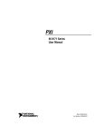
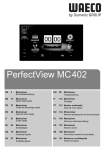
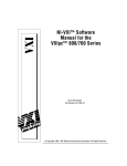
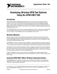
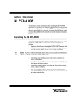
VXIPC™ 770/870B SERIES INSTALLATION AND
TROUBLESHOOTING
This guide contains information about installing and troubleshooting your
VXIpc 770/870B Series controller and components. This guide refers to
the VXIpc 770/870B Series User Manual, which you should have received
in either hardcopy or PDF format with your VXI controller. The PDF
version of this manual is also available online at ni.com/support.
Electrostatic discharge can damage your controller. To avoid such damage,
handle the controller only in a proper ESD-controlled environment.
Caution
Installing the VXIpc 770/870B Series
This section contains general installation instructions for the
VXIpc 770/870B Series controller. Consult your VXIbus chassis user
manual or technical reference manual for specific instructions and
warnings.
1.
Plug in your chassis before installing the controller. The power cord
grounds the chassis and protects it from electrical damage while you
are installing the controller.
To protect both yourself and the chassis from electrical hazards, the chassis
should remain off until you finish installing the controller.
Caution
2.
Remove or open any doors or covers blocking access to the
chassis slots.
If the controller is not configured for automatic System Controller detection, be
certain that the slot you select in your VXIbus chassis matches the controller configuration
as either a System Controller device or a Non-System Controller device. Installing the
controller into a slot that does not correspond with the jumper setting can damage the
controller, the VXIbus backplane, or both. See the VXIpc 770/870B Series User Manual
for jumper configuration information.
Caution
National Instruments™, NI™, ni.com™, and VXIpc™ are trademarks of National Instruments Corporation. Product and
company names mentioned herein are trademarks or trade names of their respective companies. For patents covering
National Instruments products, refer to the appropriate location: Help»Patents in your software, the patents.txt file
on your CD, or ni.com/patents.
ni.com
© 2002 National Instruments Corp. All rights reserved.
March 2002
323118A-01
3.
Insert the controller in the desired slot by aligning the top and bottom
of the controller with the card-edge guides inside the chassis. Slowly
push the controller straight into the slot until its plug connectors are
resting on the backplane receptacle connectors. Using slow, evenly
distributed pressure, press the module straight in until it seats in the
expansion slot. The front panel of the controller should be even with
the front panel of the chassis.
4.
Tighten the retaining screws on the top and bottom edges of the
front panel.
5.
Check the installation.
6.
Connect the keyboard and mouse to the appropriate PS/2 connectors.
7.
Connect the VGA monitor video cable to the VGA connector.
8.
Connect devices to ports as required by your system configuration.
9.
Replace or close any doors or covers on the chassis.
10. Turn on the chassis.
11. The controller should now boot. If the controller does not boot, see
What if the VXIpc 770/870B Series does not boot? in the
Troubleshooting section.
12. On the first boot of the controller, a setup program automatically runs.
13. Follow the prompts in the setup program to fully configure your
controller.
14. When prompted for the Windows serial number, enter the serial
number of the operating system from the included certificate.
15. Your controller is now ready for development.
Figure 1 shows a VXIpc-872B installed in the system controller slot of
a National Instruments VXI chassis. You can place VXI devices in any
other slot.
VXIpc 770/870B Series Installation and Troubleshooting
2
ni.com
2
1
1
VXIpc-872B Controller
2
VXI Chassis
Figure 1. VXIpc-872B Controller Installed in a VXI Chassis
How to Remove the Controller from the VXI Chassis
The VXIpc 770/870B Series controllers are designed for easy handling.
To remove the controller from the VXI chassis:
1.
Shut down all applications and the operating system.
2.
Turn off power.
3.
Disconnect devices from the front panel ports as your system
configuration requires.
4.
Remove the retaining screws in the controller front panel.
5.
Push the upper ejector handle up and the lower ejector handle down
until the controller pops out of the backplane connectors.
6.
Slide the controller out of the chassis.
© National Instruments Corporation
3
VXIpc 770/870B Series Installation and Troubleshooting
Removing the VXIpc 770/870B Series Component
Side Cover
The VXIpc 770/870B Series is housed in a metal enclosure comprised of
a top and bottom cover to improve EMC performance and provide easy
handling. To access the jumper settings or install modules such as RAM or
PCI cards, you must remove the component side cover.
Remove the top cover by removing the screws that attach it to the module.
Installing and Upgrading RAM
The VXIpc 770/870B Series uses 144-pin 133 MHz SDRAM and supports
64, 128, 256, and 512 MB SO-DIMMs, for a maximum of 512 MB. There
are two RAM sockets in the VXIpc 770/870B Series, and you can change
the amount of installed RAM by upgrading the SO-DIMMs.
National Instruments recommends the following size SO-DIMMs for use
with the VXIpc 770/870B Series controller (SDRAM):
64 MB
128 MB
256 MB
4 MB × 64 SO-DIMMs—10 ns, 1.05 in. max.
8 MB × 64 SO-DIMMs—10 ns, 1.05 in. max.
16 MB × 64 SO-DIMMs—10 ns, 1.05 in. max.
National Instruments has tested and verified that the SO-DIMMs we sell work with
the VXIpc 770/870B Series. We recommend you purchase your SO-DIMM modules from
National Instruments. Other off-the-shelf SO-DIMM modules are not guaranteed to work
properly.
Note
To add or replace RAM for the VXIpc 770/870B Series, follow these steps:
1.
Remove the VXIpc 770/870B Series from the chassis. See the removal
instructions in the How to Remove the Controller from the VXI Chassis
section.
2.
Remove the component side cover. See the removal instructions in the
Removing the VXIpc 770/870B Series Component Side Cover section.
3.
Add the SO-DIMM modules to the empty SO-DIMM sockets.
See Figure 2.
To ensure proper memory operation with a single-SO-DIMM configuration, always
populate slot XA2. For a two-SO-DIMM configuration, populate slot XA2 with the higher
capacity SO-DIMM.
Note
VXIpc 770/870B Series Installation and Troubleshooting
4
ni.com
3
2
1
1
SO-DIMM Socket XA1
2
SO-DIMM Module
3
SO-DIMM Socket XA2
Figure 2. Installing a SO-DIMM in a VXIpc 770/870B Series Controller
Installing and Removing the Internal Hard Drive
Follow these steps to remove the internal hard drive from your
VXIpc 770/870B Series controller:
1.
Remove the controller from the chassis. See the removal instructions
in the How to Remove the Controller from the VXI Chassis section.
2.
Remove the component side cover. See the removal instructions in the
Removing the VXIpc 770/870B Series Component Side Cover section.
3.
Remove the four screws under the solder side cover that hold the hard
drive in place.
4.
Carefully and slowly slide the hard drive toward the rear of the
controller to free the pins from the IDE connector.
Be careful when sliding the hard drive toward the rear of the controller. The hard
drive could contact components on the motherboard, causing severe damage to both the
components and motherboard.
Caution
5.
© National Instruments Corporation
When the pins are free of the connector, lift the hard drive off the
motherboard.
5
VXIpc 770/870B Series Installation and Troubleshooting
Note Always handle the hard drive in accordance with the handling instructions outlined
by the hard drive manufacturer.
Follow these steps to install the internal hard drive in your VXIpc 770/870B
Series controller:
1.
Be sure the insulating pad is properly placed on the motherboard over
the hard drive ground plane.
2.
Set the hard drive on the motherboard and carefully slide the drive
forward until it seats firmly in the IDE connector. The insulating pad
should be between the hard drive and the motherboard.
Caution Use care when installing the hard drive. The rear of the hard drive could contact
components on the motherboard, causing severe damage to both the components and
motherboard.
3.
Reinstall the four screws that hold the hard drive in place.
4.
Reinstall the component side cover.
The controller is now ready to be reinstalled in the VXI mainframe.
Troubleshooting
What if the VXIpc 770/870B Series does not boot?
Several problems can cause a controller not to boot. Here are some things
to look for and possible solutions.
Things to Notice:
•
Which LEDs come on? The PWR LED should stay lit. The IDE LED
should blink during boot as the disk is accessed.
•
What appears on the display? Does it hang at some particular point
(BIOS, Operating System, etc.)? If nothing appears on the screen,
try a different monitor. Does your monitor work with a different PC?
If it hangs, note the last screen output that you saw for reference when
consulting National Instruments technical support.
•
What has changed about the system? Did you recently move the
system? Was there electrical storm activity? Did you recently add a
new module, memory chip, or piece of software?
Things to Try:
•
Make sure the chassis is plugged into a working power source.
•
Check any fuses or circuit breakers in the chassis or other power
supply (such as a UPS).
•
Make sure the controller module is firmly seated in the chassis.
VXIpc 770/870B Series Installation and Troubleshooting
6
ni.com
•
Remove all other modules from the chassis.
•
Remove any nonessential cables or devices.
•
Try the controller in a different chassis.
•
Try a similar controller in this same chassis.
•
Recover the hard drive on the controller. (For more information,
see the VXIpc 770/870B Series User Manual.)
•
Clear the CMOS. (For more information, see the VXIpc 770/870B
Series User Manual.)
My controller boots fine until I get to Windows, at which point I cannot
read the screen. This may include garbled output, white screen, black
screen, or an out of sync message from the monitor.
This problem usually results from having the video card output set past the
limits of the monitor. You will need to boot Windows in Safe Mode. To do
this, reboot the controller. As Windows begins to boot, hold down <F8>.
For Windows NT, select Windows NT (VGA MODE) from the boot
manager. You should now be able to reset the video driver to lower settings.
Try setting the resolution to 640 × 480 and the refresh rate to 60 Hz. Once
you reboot, you can raise these values again, using the test option in
Windows. These settings are accessible through the Advanced tab of the
Display item in the Control Panel. Alternately, you can try a different
monitor, preferably a newer and larger one.
How do I restore the operating system on my VXIpc 770/870B Series
controller?
The VXIpc 770/870B Series controllers include a recovery CD. There are
two methods for recovering the hard disk to its original state—recovery
from a CD-ROM or from a network. For more information, see the
VXIpc 770/870B Series User Manual.
My CMOS is corrupted. How do I set it back to default?
1.
Enter the BIOS setup program as described in the VXIpc 770/870B
Series User Manual.
2.
Press <F9> to load BIOS defaults.
3.
Answer Y (Yes) to the verification prompt.
4.
Select Save and Exit Setup.
I can’t change the display on the controller from 640 × 480 to
800 × 600. What’s wrong?
Be sure the video driver is installed. If it is not, see the Drivers.txt file
on the hard drive or recovery CD-ROM.
© National Instruments Corporation
7
VXIpc 770/870B Series Installation and Troubleshooting
What if there is a power loss during a BIOS update?
Create a crisis recovery disk. Unzip crisis.zip on the recovery
CD. Insert a blank floppy disk in the PC. Run crisis.exe (or
Wincrisis.exe in Windows). Follow the instructions to create the
BIOS recovery floppy disk. Insert the disk in the floppy drive and
power on the controller. The controller installs the BIOS from the disk.
National Instruments Technical Support
For VXIpc 770/870B Series technical support, contact National
Instruments:
Internet Support
Web address: ni.com/support
FTP site: ftp.ni.com/support
Telephone Support
Phone: 512 795 8248
Fax: 512 683 5678
Mailing Address
11500 North Mopac Expressway
Austin, TX 78759-3504 USA
512 683 0100
*323118A-01*
323118A-01
Mar02