1
TV EXPLORER HD DTMB
UNIVERSAL TV EXPLORER
- 0 MI1903 -
SAFETY NOTES
Read the user’s manual before using the equipment, mainly " SAFETY RULES "
paragraph.
The symbol
on the equipment means "SEE USER’S MANUAL". In this manual
may also appear as a Caution or Warning symbol.
Warning and Caution statements may appear in this manual to avoid injury
hazard or damage to this product or other property.
USER’S MANUAL. TV EXPLORER HD DTMB
T A B L E
1
2
3
4
5
O F
C O N T E N T S
GENERAL.................................................................................................................. 1
1.1 Description .......................................................................................................... 1
1.2 Specifications ...................................................................................................... 4
SAFETY RULES...................................................................................................... 11
2.1 General safety rules .......................................................................................... 11
2.2 Descriptive Examples of Over-Voltage Categories ........................................... 12
INSTALLATION ....................................................................................................... 13
3.1 Power Supply .................................................................................................... 13
3.1.1 Operation using the External DC Charger .................................................. 13
3.1.2 Operation using the Battery ........................................................................ 13
3.1.2.1
Battery Charging ............................................................................... 14
3.2 Installation and Start-up .................................................................................... 14
QUICK USER GUIDE .............................................................................................. 15
OPERATING INSTRUCTIONS................................................................................ 19
5.1 Description of the Controls and Elements ......................................................... 19
5.2 Adjustment of Volume and Monitor Parameters................................................ 29
5.3 Selecting the Operation Mode: TV / Spectrum Analyser / Measurements ........ 29
5.4 Channel Tuning / Frequency Tuning ................................................................. 30
5.5 Automatic Transmission Search........................................................................ 30
5.6 Selecting the measurement configuration: Analogue/ Digital signal ................. 30
5.7 External Units Power Supply............................................................................. 31
5.8 Automatic signal identification function (AUTO ID) ........................................... 32
5.9 Channel plans ................................................................................................... 33
5.10 Acquisition function (DATALOGGER) ............................................................... 35
5.11 Verification of distribution networks................................................................... 38
5.12 Spectrum exploration function (EXPLORER).................................................... 40
5.13 Measurements configuration ............................................................................. 41
5.13.1 DVB-C (QAM) Digital Channel Configuration ............................................. 41
5.13.2 DTMB Digital Channel Configuration .......................................................... 42
5.13.3 DVB-S/S2 (QPSK/8PSK) Digital Channel Configuration ............................ 43
5.14 Selecting the Measurements............................................................................. 45
5.14.1 Analogue TV: Measuring the Video Carrier Level....................................... 46
5.14.2 Analogue TV: Measuring the Video / Audio ratio (V/A)............................... 48
5.14.3 Analogue TV: Measuring the FM deviation................................................. 48
5.14.4 Analogue FM: Measuring the Level and demodulating signal .................... 49
5.14.5 Analogue/Digital TV: Measuring the Carrier / Noise ratio (C/N).................. 50
5.14.6 Digital TV: Measuring the Power of Digital Channels ................................. 52
5.14.7 Digital TV: Measuring BER ......................................................................... 52
5.14.7.1
ITU-T J.83/B signals ......................................................................... 53
5.14.7.2
DVB-C signals................................................................................... 54
5.14.7.3
DTMB signals.................................................................................... 55
5.14.7.4
DVB-S/S2 signals ............................................................................. 56
5.14.8 Digital TV: Measuring MER......................................................................... 59
USER’S MANUAL. TV EXPLORER HD DTMB
5.15 Constellation Diagram ....................................................................................... 61
5.15.1 ITU-T J.83/B (QAM-Annex B) signal........................................................... 61
5.15.1.1
Zoom, scroll and erasing functions ................................................... 62
5.15.2 DTMB signal ............................................................................................... 63
5.15.3 DVB-C (QAM) signal................................................................................... 64
5.15.4 DVB-S/S2 (QPSK/8PSK) signal.................................................................. 64
5.16 Spectrum Analyser ............................................................................................ 66
5.16.1 Markers ....................................................................................................... 68
5.16.2 Spectrogram. .............................................................................................. 68
5.16.2.1
Spectrogram Configuration ............................................................... 70
5.16.2.2
Recall a Spectrogram file.................................................................. 71
5.16.2.3
Delete a Spectrogram file ................................................................. 72
5.17 ECHOES and PRE-ECHOES Analyser (DTMB)............................................... 72
5.18 Screen capture .................................................................................................. 75
5.18.1 Recall screen .............................................................................................. 75
5.18.2 Delete capture............................................................................................. 76
5.19 PRINT SCREEN function .................................................................................. 76
5.20 VIEWPRINT SCREEN ...................................................................................... 76
5.21 USB On-the-Go Function .................................................................................. 77
5.21.1 Connection of TV EXPLORER HD DTMB (host) to a USB flash drive (slave)..... 77
5.21.1.1
Connecting a computer (host) to the TV EXPLORER HD DTMB (slave).. 79
5.22 Setting the TS-ASI Input-Output........................................................................ 80
5.23 TV Operating Mode ........................................................................................... 82
5.23.1 Recording and playing video streams......................................................... 86
5.24 Antenna Alignment Function ............................................................................. 87
5.25 DiSEqC Command Generator........................................................................... 88
5.26 SATCR function................................................................................................. 90
5.27 Using the alphanumeric keyboard..................................................................... 90
6 DESCRIPTION OF THE INPUTS AND OUTPUTS ................................................. 93
6.1 RF input............................................................................................................. 93
6.2 TS-ASI Input / Output ........................................................................................ 93
6.3 USB port............................................................................................................ 93
6.4 HDMI Conector (High-Definition Multimedia-Interface) ..................................... 93
6.5 Scart (DIN EN 50049) ....................................................................................... 94
6.6 Connector for CAM modules and SMART-CARD. ................................................. 95
7 MAINTENANCE....................................................................................................... 97
7.1 Considerations about the Screen. ..................................................................... 97
7.2 Cleaning Recommendations ............................................................................. 97
USER’S MANUAL. TV EXPLORER HD DTMB
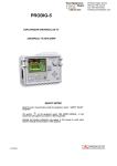
UNIVERSAL TV EXPLORER
®
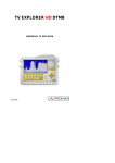
TV EXPLORER HD DTMB
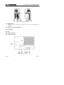
1
1 GENERAL
1.1
Description
The television explorer TV EXPLORER HD DTMB represents an evolutionary step
with respect to the traditional field strength meters. This new jewel of the PROMAX
range will become a reference in the industry for being the very first meter of its kind to
actually meet the requirements to be called a real HDTV instrument. The continuous
PROMAX innovation process in the sector of field strength meter yields an instrument
that changes the way to take and understand television signals measurements.
This equipment incorporates important advances in the functional aspects as
well as in the ergonomics to allow the installers to make their work with maximum
comfort and speed. Simultaneously the instrument is reliable for any possible problem
at the input signal, at the distribution components or the receiver equipment.
Millions of people in Europe are now served with digital TV broadcasting only.
Analogue switch off is history for them. For these and those who still are in the migration
process from analogue to digital, the use of digital TV distribution equipment will be more
frequent every day. The typical high definition formats used in nowadays broadcast are
1080i (1920x1080 pixels) and 720p (1280x720 pixels). Most of the TV programmes
using these video resolutions are being broadcasted compressed in MPEG-4. The
TV EXPLORER HD DTMB is able to display those TV programmes thanks to its state of
the art electronics.
HDTV content is expensive to produce and therefore it is usually protected by
encryption. Once again the TV EXPLORER HD DTMB is setting new standards with its
CAM interface that allows the encrypted high definition programmes to be displayed as
well.
TV EXPLORER®
1
09/2011
is a registered trademark PROMAX Electronica S.A.
Trademark of the DVB - Digital Video Broadcasting Project.
Page 1
USER’S MANUAL. TV EXPLORER HD DTMB
The TV EXPLORER HD DTMB has an HDMI connector (High-Definition Multimedia Interface) which allows the use of standard, enhanced or high definition video, as
well as 8 audio digital channels without compression. With no doubt, it will become the
digital replacement for analogue standards such as the Euroconnector (SCART).
The TV EXPLORER HD DTMB also has a DVB-ASI standard interface, which
allows both the input and output of transport streams. Automatically detects whether the
stream is composed by 188 or 204 bytes, and can transmit data in packet mode or burst
mode. You can select the input you want to decode between the external ASI and the
internal demodulator, and what data you want in the ASI output, either from the
demodulator or the CAM module. Therefore, to have TS-ASI inputs and outputs
becomes an essential feature for a TV analyser ready for the future.
When pressing the auto identification key, it searches and identifies the signal
under test. First it recognises whether the signal is an analogue channel or a digital one.
If the channel is analogue, it determines the television standard of the signal. When the
signal is digital (DVB), it analyses for each modulation type QAM / QPSK / 8PSK /
DTMB all the associated parameters such as the modulation system: symbol rate, code
rate, etc. and determines the value of the signals under test.
The range of frequencies covered makes this instrument an excellent tool for FM
radio, terrestrial TV, mobile TV, satellite TV and cable TV (where the sub band tuning
margin, from 5 to 45 MHz, enables the user to carry out tests on the return channel).
The TV EXPLORER HD DTMB includes the main TV standards: M, N, B, G, I, D,
K and L, adopting, apart from the characteristic parameters of the standard, the
correcting automatic system to obtain in all the cases an accurate measuring of the input
signal level. It accepts any TV system (PAL, SECAM and NTSC) and allows the user to
work directly with digital TV signals decoding them, so that the television image may be
viewed, and directly measuring the power, carrier/noise ratio (C/N), the bit error rate
(BER) and the modulation error ratio (MER), as well for DTMB as DVB-S/S2
(QPSK/8PSK) and DVB-C (QAM) signals. This instrument allows to obtain a graphical
representation of the Constellation Diagram for DVB-C (QAM), DTMB and DVB-S/S2
(QPSK/8PSK) signals.
Being a multistandard instrument, it can be efficiently used in any country of the
world.
Includes a symbol-based keyboard that allows the direct access to the various
functions that are displayed simultaneously on screen.
Page 2
09/2011
USER’S MANUAL. TV EXPLORER HD DTMB
The TV EXPLORER HD DTMB makes a dynamic exploration of the spectrum,
detecting all the channels in the explored band, this applies for the terrestrial and the
satellite television bands. The meter locates all the channels in the spectrum with no
need of any previous information about the number of channels, the type of signals
transmitted or their characteristics. With the data collected after each exploration, it
creates a register that contains tables of channels that can be independent for each
system or installation. At any time, the measurement sessions using only the pretuned
channels can be repeated. In this way it is possible to optimise the measurement
process.
Shown on the frontal panel is the type of measurement that is being carried
(Terrestrial-Satellite/Analogue-Digital) and the data are presented on a hi-res 6.5" colour
graphic TFT transflective display with panoramic aspect ratio (16:9). The equipment
incorporates a light sensor that activates the contrast and luminosity of the display
according to the environmental conditions.
Furthermore the TV EXPLORER HD DTMB comes with a connector for CAM
modules (PC-Card) that allows the insertion of subscriber conditional access cards.
The TV EXPLORER HD DTMB is an ideal size to hold with a hand. The
instrument can be held to the body with the carrying bag or transport belt, which at the
same time protects it from the rain. Because it is designed for outdoor use, it includes an
anti-shock protector that completely covers the instrument, and is supplied with a strong
transport case. As well, the front panel does not have any keys nor gaps to avoid
accidental water ingress.
The TV EXPLORER HD DTMB is designed to integrate measurements that
require different operating configurations. In this way it incorporates a specific function to
facilitate the alignment of antennas. When activating the alignment function the
instrument is set automatically to offer a fast spectrum sweep and a high sensitivity
graphical bar that allows fine adjust for the maximum signal. In addition it includes a
module for the powering of LNBs and DTMB antennas to 5V, and the commands for
the programming of DiSEqC 1.2 and SatCR devices.
The TV EXPLORER HD DTMB can be updated to new software versions that
extend the available functions in the future. That means it can incorporate new benefits
without additional cost. For example, in the test of satellite signals distribution
networks, using combined with an IF generator permits to carry out an easy verification
of the installations before commissioning.
The spectrum analyser features with high accuracy, resolution, sensitivity and
sweep speed allows the instrument to be very useful for applications as the installation
of antennas. It presents an innovative control system based on four arrows, that makes
the use of the spectrum analyser very intuitive. The arrows allow adjusting the reference
level by steps of 10 or 5 dB and the frequency margin span on screen.
09/2011
Page 3
USER’S MANUAL. TV EXPLORER HD DTMB
To enhance its convenience of use, it includes memories to store automatically
the different data acquisitions, i.e.: acquisition name, test points, frequency, channel
plan, etc. Moreover, the DATALOGGER function makes it much easier to test systems
in which a large number of measurements have to be made, and enables further
processing of all the information acquired using a computer system. The equipment is
able to generate automatic measurement reports and to update itself through Internet by
means of PkTools provided software.
The TV EXPLORER HD DTMB in addition, allows to record and to play a TS
corresponding to services from a digital channel. For it, the equipment uses an internal
memory of up to 1 GB.
Also, this meter incorporates a DiSEqC2 command generator and permits to
supply different voltages to the external unit (5 V / 13 V / 15 V / 18 V / 24 V) and includes
an EUROCONNECTOR, or Scart connector, for audio/video input/output.
The TV EXPLORER HD DTMB is powered by rechargeable battery or connected
to the mains through the supplied external DC power charger.
It incorporates a “USB On-the-go“ port, which enables the communication with a
PC and to download dataloggers and channel plans.
This instrument due to its extreme-compact design, technical specifications and
low cost becomes the industry standard for the installer.
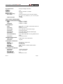
1.2
Specifications
CONFIGURATION FOR MEASURING LEVEL AND POWER
TUNING
Tuning modes
Resolution
Automatic search (Explorer)
2
Digital frequency synthesis. Continuous tuning from
5 to 1000 MHz and from 950 to 2150 MHz.
(Terrestrial and Satellital respectively).
Channel or frequency (IF or downlink at satellite
band).
Channel plan configurable on demand.
5-1000 MHz:
50 kHz.
950-2150 MHz: < 200 kHz (span FULL-500-200100-50-32-16 MHz).
Threshold level selectable. DTMB, DVB-C, DVB-S
and DVB-S2 selection.
DiSEqCTM is a trademark of EUTELSAT.
Page 4
09/2011
USER’S MANUAL. TV EXPLORER HD DTMB
Signal identification
RF INPUT
Impedance
Connector
Maximum signal
Maximum input voltage
DC to 100 Hz
5 MHz to 2150 MHz
Analogue and digital. Automatic.
75 Ω.
Universal, with BNC or F adapter.
130 dBµV.
50 Vrms (powered by the AL-103 power charger).
30 Vrms (not powered by the AL-103 power
charger).
130 dBµV.
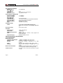
DIGITAL SIGNALS MEASUREMENT
MARGIN OF POWER MEASUREMENT
DTMB:
45 dBµV to 100 dBµV.
QAM:
45 dBµV to 110 dBµV.
QPSK/8PSK:
44 dBµV to 114 dBµV.
MEASUREMENTS
DTMB
Presentation
Power, MER, C/N, LBER, LDPC Iterations and Link
Margin.
Numeric and level bar.
DVB-C (QAM):
Presentation:
Power, BER, MER, C/N and Noise margin.
Numeric and level bar.
DVB-S (QPSK):
Presentation:
Power, CBER, VBER, MER, C/N and Noise margin.
Numeric and level bar.
DVB-S2 (QPSK/8PSK):
Power, CBER, LBER, MER, C/N, wrong packets and Link
Margin.
Numeric and level bar.
Presentation:
CONSTELLATION DIAGRAM
Type of signal
Presentation
DTMB, DVB-C, DVB-S and DVB-S2.
I-Q graph.
DTMB SIGNAL PARAMETERS
Carriers
Guard Interval
Code Rate
Modulation
Bandwidth
Time interleaver
DVB-C SIGNAL PARAMETERS
Demodulation
Symbol rate
Roll-off (α) factor
of Nyquist filter
Spectral inversion
09/2011
Multi Carrier or Single Carrier.
420, 595, 945.
0.40, 0.60, 0.80.
4QAM, 4QAM-NR, 16QAM, 32QAM, 64QAM.
8 MHz.
240, 720.
16/32/64/128/256 QAM.
1000 to 7000 kbauds.
0.15.
Selectable: ON, OFF.
Page 5
USER’S MANUAL. TV EXPLORER HD DTMB
DVB-S SIGNAL PARAMETERS
Symbol rate
Roll-off (α) factor
of Nyquist filter
Code Rate
Spectral inversion
DVB-S2 SIGNAL PARAMETERS
Symbol rate (QPSK)
Symbol rate (8PSK)
Roll-off (α) factor
of Nyquist filter
Code Rate (QPSK)
Code Rate (8PSK)
Spectral inversion
Pilots
STANDART VIDEO
Format
Services decoding
HD VIDEO
Input resolution
Aspect Ratio
HDMI Output Resolution
Audio
Compression type
2 to 45 Mbauds.
0.35.
1/2, 2/3, 3/4, 5/6, 7/8 and AUTO.
Selectable: ON, OFF.
1 to 45 MSps.
1 to 45 MSps.
0.20, 0.25 and 0.35.
1/4, 1/3, 2/5, 1/2, 3/5, 2/3, 3/4, 4/5, 5/6, 8/9, 9/10 and AUTO.
3/5, 2/3, 3/4, 5/6, 8/9, 9/10 and AUTO.
Selectable: ON, OFF.
Indication if are present.
DVB: MPEG-2 (MP@HL) (Main Profile High Level).
MPEG-4 AVC H.264 (free or scrambled) (High Profile Level
4.1)
Service list and PIDs.
1080i, 720p and 576i.
16:9 and 4:3.
1920 x 1080.
MPEG-1, MPEG-2, HE-AAC, Dolby Digital and
Dolby Digital Plus.
MPEG-2 y MPEG-4 H.264.
ANALOGUE SIGNALS MEASUREMENT
LEVEL MEASUREMENT
Measurement range
Terrestrial TV & FM bands
Satellite TV band
Reading
Digital
Analogue
Measurement bandwidth
Audible indicator
Page 6
10 dBµV to 130 dBµV (3.16 µV to 3,16 V).
30 dBµV to 130 dBµV (31.6 µV to 3,16 V).
Auto-range, reading is displayed on an OSD
window.
Absolute value calibrated in dBµV, dBmV or dBm.
Relative value through an analogue bar on the
screen.
230 kHz (Terrestrial band) 4 MHz (Satellite band)
According to span (maximum band ripple 1 dB).
LV audio. A tone with pitch proportional to signal
strength.
09/2011
USER’S MANUAL. TV EXPLORER HD DTMB
Accuracy
Subband
Terrestrial bands
Satellite band
Over range indication
MEASUREMENTS MODE
Terrestrial bands
Analogue channels
Digital channels
Satellite band
Analogue channels
Digital channels
±1,5 dB (30-120 dBµV, 5-45 MHz) (22 °C±5 °C).
±1.5 dB (30-120 dBµV, 45-1000 MHz) (22 °C±5 °C).
±2.5 dB (40-100 dBµV, 950-2050 MHz) (22 °C ± 5 °C).
< >.
Level, Video-Audio ratio, Carrier-Noise ratio and
frequency deviation.
Channel power, Carrier-Noise ratio and Channel
identification.
Level and Carrier-Noise ratio.
Channel power and Carrier-Noise ratio.
DATALOGGER function3
Analogue channels
Digital channels
Measurements automatic acquisition and storage.
Level, C/N and V/A ratios.
Frequency offset, MPEG-2 / MPEG-4 detection,
power, C/N, MER, CBER, VBER, LBER and noise
margin.
SAT IF TEST Function4
ATTENUATION TEST Function5
IF distribution network response for satellite band.
Signal distribution network response for terrestrial
band.
SPECTRUM ANALYSER MODE
Satellite band
Terrestrial bands
Measurement bandwidth
Terrestrial
Satellite
Span
Terrestrial
Satellite
Markers
Vertical range
Measurements
Terrestrial bands
Analogue channels
Digital channels
30 dBµV to 130 dBµV (31.6 µV to 3.16 V).
10 dBµV to 130 dBµV (3.16 µV to 3.16 V).
According to span.
230 kHz, 1 MHz.
4 MHz, 1 MHz.
Full span (full band) - 500 - 200 - 100 - 50 - 32 - 16
- 8 MHz selectable.
Full span (full band) - 500 - 200 - 100 - 50 - 32
- 16 MHz selectable.
1 with Frequency and level or C/N indications.
Adjustable in steps of 5 or 10 dB.
Level.
Channel power.
3
Using PkTools software application with a PC.
4
Function to be used with RP-250 or RP-050 IF signal simulator.
5
Function to be used with RP-250 or RP-080 pilot signals simulator.
09/2011
Page 7
USER’S MANUAL. TV EXPLORER HD DTMB
Satellite band
Analogue channels
Digital channels
Level.
Channel power.
ECHOES ANALYSER MODE (DTMB)
Measurement range
Delay
0.1 µs to 200 µs.
Distance
0.3 km to 60 km.
Power range
0 dBc to —30 dBc.
MONITOR DISPLAY
Monitor
Aspect ratio
Colour system
TV standard
Spectrum mode
Sensibility
TFT colour 6.5 inches. Transflective LCD.
16:9, 4:3.
PAL, SECAM and NTSC.
M, N, B, G, I, D, K and L.
Variable span, dynamic range and reference level by
means of arrow cursors.
40 dBµV for correct synchronism.
BASE BAND SIGNAL
VIDEO
Format
Conditional access types
External video input
Sensibility
Video output
SOUND
Input
Outputs
Demodulation
De-emphasis
Subcarrier
USB INTERFACE
DVB-ASI INTERFACE
Type
Connectors
Packets
Page 8
DVB: MPEG-2 (MP@HL).
MPEG-4 AVC H.264 (free or scrambled).
Common Interface, according to available user CAM.
Scart.
1 Vpp (75 Ω) positive video.
Scart (75 Ω).
Scart.
Built in speaker, Scart.
TV PAL, SECAM, NTSC system according to
DTMB, DVB-C, DVB-S/S2 and MPEG standards.
50 µs, 75 µs (NTSC).
Digital frequency synthesis according to the TV
standard.
“USB On-the-go” for datalogger and channel plans
transfer.
Mass Storage Host: The equipment can read /
write on Flash drives.
Serial Port Emulation.
USB CDC: (Communications Device Class).
1 DVB-ASI input and 1 DVB-ASI output.
Female BNC, impedance 75 Ω.
Transport Stream of 188 or 204 bytes (automatic
detection).
09/2011
USER’S MANUAL. TV EXPLORER HD DTMB
Transmission
Packet or burst mode.
EXTERNAL UNITS POWER
SUPPLY
Terrestrial and Satellite
22 kHz signal
Voltage
Frequency
Maximum power6
Through the RF input connector.
External or 5/13/15/18/24 V.
Selectable in satellite band.
0.65 V ± 0.25 V.
22 kHz ± 4 kHz.
5 W.
DiSEqC7 GENERATOR
According to DiSEqC 1.2 standard.
POWER SUPPLY
Internal
Batteries
Autonomy
Recharging time
External
Voltage
Consumption
Auto power off
7.2 V 12 Ah Li-Ion battery.
> 4.5 hours in continuous mode.
3 hours up to 80% (instrument off).
12 V.
40 W.
Programmable. After the selected amount of
minutes without operating on any control.
Deactivable.
OPERATING ENVIRONMENTAL CONDITIONS
Altitude
Up to 2000 m.
Temperature range
From 5 to 40 °C (Automatic disconnection by excess
of temperature).
Max. relative humidity
80 % (up to 31°C),
decreasing lineally up to 50% at 40 °C.
MECHANICAL FEATURES
Dimensions
Weight
230 (W) x 161 (H) x 76 (D) mm.
(Total size: 2.814 cm3).
2.2 kg (without holster).
INCLUDED ACCESSORIES.
1x
1x
1x
1x
1x
1x
1x
1x
CB-077
AT-010
AD-055
AD-056
AD-057
AL-103
DC-229
DC-267
Rechargeable Li+ battery 7,2 V 12 Ah.
10 dB attenuator.
"F"/F-BNC/F adapter.
"F"/F-"DIN"/F adapter.
"F"/F-"F"/F adapter.
External DC charger.
Transport suitcase.
Carrying bag.
6
If you select 5V, the maximum power shall not exceed 2.25 W (450 mA).
7
DiSEqCTM is a trademark of EUTELSAT
09/2011
Page 9
USER’S MANUAL. TV EXPLORER HD DTMB
1x
1x
1x
1x
1x
1x
DC-289
AA-103
CC-041
CC-045
CA-005
Transport belt.
Car lighter charger.
Connection USB Cable On-the-go (A) Male — Mini USB (B) Male.
USB Cable (A) Female — Mini USB (A) Male.
Mains cord.
USB Memory.
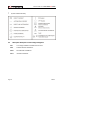
RECOMMENDATIONS ABOUT THE PACKING
It is recommended to keep all the packing material in order to return the
equipment, if necessary, to the Technical Service.
Page 10
09/2011
USER’S MANUAL. TV EXPLORER HD DTMB
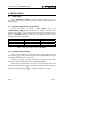
2 SAFETY RULES
2.1
*
*
*
*
*
General safety rules
The safety could not be assured if the instructions for use are not closely
followed.
Use this equipment connected only to systems with their negative of
measurement connected to ground potential.
The AL-103 external DC charger is a Class I equipment, for safety reasons plug it
to a supply line with the corresponding ground terminal.
This equipment can be used in Overvoltage Category I installations and
Pollution Degree 2 environments.
External DC charger can be used in Overvoltage Category II, installation and
Pollution Degree 1 environments.
When using some of the following accessories use only the specified ones to
ensure safety.
Rechargeable battery
External DC charger
Car lighter charger cable
Power cord
*
*
*
*
*
*
*
Observe all specified ratings both of supply and measurement.
Remember that voltages higher than 70 V DC or 33 V AC rms are dangerous.
Use this instrument under the specified environmental conditions.
When using the power adaptor, the negative of measurement is at ground
potential.
Do not obstruct the ventilation system of the instrument.
Use for the signal inputs/outputs, specially when working with high levels,
appropriate low radiation cables.
Follow the cleaning instructions described in the Maintenance paragraph.
09/2011
Page 11
USER’S MANUAL. TV EXPLORER HD DTMB
*
Symbols related with safety:
2.2
Descriptive Examples of Over-Voltage Categories
Cat I
Low voltage installations isolated from the mains.
Cat II
Portable domestic installations.
Cat III
Fixed domestic installations.
Cat IV
Industrial installations.
Page 12
09/2011
USER’S MANUAL. TV EXPLORER HD DTMB
3 INSTALLATION
3.1
Power Supply
The TV EXPLORER HD DTMB is a portable instrument powered by one 7.2 V
Li-Ion battery. There is also an external DC charger provided for mains connection and
battery charging.
3.1.1 Operation using the External DC Charger
Connect the external DC charger to EXT. SUPPLY [32] on the
TV EXPLORER HD DTMB side panel. Connect the DC charger to the mains. Then,
press the rotary selector
[1] for more than two seconds. The level meter is now in
operation and the battery is slowly charged. When the instrument is connected to the
mains, the CHARGER indicator [4] remains lit. This indicator changes of colour
according to the battery charge status:
RED
ORANGE
GREEN
BATTERY CHARGE STATUS
OFF
< 50 %
> 50 %
100 %
ON
< 90 %
> 90 %
100 %
Table 1.- Indication of the battery charge status (CHARGER).
3.1.2 Operation using the Battery
For the device to operate on the battery, disconnect the power cable and press the
[1] for more than two seconds. The fully charged battery can power
rotary selector
the equipment for more than 4.5 hours non-stop.
If battery is very weak, the battery cut-off circuit will prevent the device from
functioning. In such a situation battery must be recharged immediately.
Before taking any measurements, you have to check the charge status of the
battery by checking the battery charge level indicator that appears when activating the
measurement mode pressing key
09/2011
[12]. These are the indicators on screen:
Page 13
USER’S MANUAL. TV EXPLORER HD DTMB
COLOUR
GREEN
BATTERY CHARGE LEVEL INDICATORS
SYMBOL
CHARGE LEVEL
75 % ∼ 100 %
30 % ∼ 75 %
GREEN
GREEN
10 % ∼ 30 %
RED
0 % ∼ 10 %
Empty battery.
Recharge in progress.
Table 2.- Indication of the battery charge level on screen.
3.1.2.1
Battery Charging
To fully charge the battery, connect the instrument to the external DC charger
without activating the power on process. The length of time it takes to recharge it
depends on the condition of the battery. When the instrument is in operation the
recharging process is slower. If they are very low the recharging period is about
5 hours. The CHARGER [4] indicator should remain lit.
When the battery charging process is completed with the instrument off, the fan
stops.
IMPORTANT
The instrument battery needs to be kept charged between 30% and 50% of its
capacity when not in use. The battery needs to be fully charged for best results. A
fully charged battery suffers temperature-related discharge. For example, at a room
temperature of 20 °C, it can lose up to 10% of its charge over 12 months.
3.2
Installation and Start-up
The TV EXPLORER HD DTMB level meter is designed for use as a portable
device. Therefore does not require installation
When the rotary selector
[1] is pressed for more than two seconds, the
instrument is started up in the automatic power-off mode; that is, the device is
automatically disconnected after the selected minutes if no key has been pressed. When
the device is operating, it is also possible to select the auto power-off mode by means
of the Preferences menu
off.
[22] and to select the time out until the automatic power-
When the equipment is going to be moved, activate the Transport mode by
[22] to disable the power on process until one
means of the Preferences menu
specific key from main keyboard is pressed [8] as is it indicated on screen.
Page 14
09/2011
USER’S MANUAL. TV EXPLORER HD DTMB
4 QUICK USER GUIDE
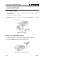
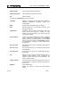
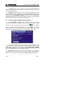
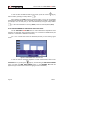
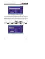
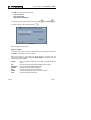
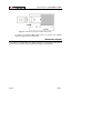
STEP 1.- Battery charging
1. Connect the DC external charger to the equipment through connector [32] located on
the lateral panel.
2. Connect the DC charger to the mains.
3. When the equipment is connected to the mains, the CHARGER led [4] remains
lighted.
Figure 1.- Battery charging
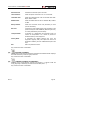
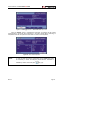
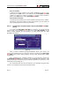
STEP 2.- Power on and signal connection
1. Hold the rotary selector
[1] pressed until the equipment is powered on.
2. Connect the RF signal source in the input connector [30].
Figure 2.- Power on and signal connection.
09/2011
Page 15
USER’S MANUAL. TV EXPLORER HD DTMB
STEP 3.- To carry out a complete channel band exploration
1. Select the frequency band to explore
[14] (terrestrial or satellite).
2. Activate the exploration process by holding
[25] key pressed.
3. Press
[10] key to visualise the channels detected and
between channels from detected channels list.
[6] to change
STEP 4.- To carry out the tuned channel identification
1. Select the frequency band to explore
[14] (terrestrial or satellite).
2. Activate the identification process pressing once on
3. Press
[25] key.
[10] key to visualise the signal detected from channel or frequency
identified or
[13] to monitor the corresponding spectrum.
NOTE: In the case that is desired to explore or identify DVB-C signals it is
necessary to select previously DVB-C standard as digital signal identifier
through
[22] PREFERENCES menu.
STEP 5.- Making measurements
1. Select the channel or frequency
[24] to measure by means of the rotary selector
[1].
2. Press
[12] key to select the type of measurement until on screen appears the
corresponding measurement.
Page 16
09/2011
USER’S MANUAL. TV EXPLORER HD DTMB
STEP 6.- Frequency spectrum monitoring
1. Select the frequency band
to graph [14] (terrestrial or satellite).
2. Press
[13] key to activate the signal sweeping.
3. Press
[6] to modify the reference level in the vertical axis.
4. Press
[6] to modify span in the horizontal axis.
STEP 7.- Video signal monitoring
1. Select the terrestrial frequency band
2. Tune the channel or frequency
[14].
[24] that is desired to visualize on screen.
3. Verify that the equipment receives an appropriate signal level
4. Press
[12].
[10] key to visualise the TV image, if the channel is digital press
and place the cursor on the Service Identifier field and press the rotary selector
[6]
[1] to obtain the available list of services.
09/2011
Page 17
USER’S MANUAL. TV EXPLORER HD DTMB
Page 18
09/2011
USER’S MANUAL. TV EXPLORER HD DTMB
5 OPERATING INSTRUCTIONS
WARNING:
The following described functions could be modified based on software updates of
the equipment, carried out after manufacturing and the publication of this manual.
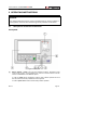
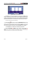
5.1
Description of the Controls and Elements
Front panel
Figure 3.- Front panel.
[1]
Rotary selector - button. This has many different functions: Equipment power
on/off, tuning control, moving between the various on-screen menus and submenus, and validation of the different options.
In order to power on the equipment, hold the rotary selector pressed for more
than two seconds until the presentation screen appears.
In order to power off the meter hold the rotary selector pressed.
09/2011
Page 19
USER’S MANUAL. TV EXPLORER HD DTMB
Tuning purposes: turning it clockwise frequency increases while turning it
anticlockwise frequency decreases.
To move along the on-screen menus: turning it clockwise active option moves
downwards while turning it anticlockwise active option moves upwards.
[2]
EXT VIDEO. Video signal presence light indicator
It lights up when video on screen is coming through the SCART connector [35].
[3]
DRAIN
External units power supply indicator. Lights up when the TV EXPLORER HD
DTMB supplies a current to the external unit.
[4]
CHARGER
External DC charger operation indicator. When batteries are installed the battery
charger is automatically activated.
[5]
SENSOR
Sensor of environmental luminosity, allows automatic adjusts of the display
contrast and brightness contributing to the battery saving.
[6]
CURSORS
Allow adjust in the Spectrum Analyser mode of the reference level and the margin
of frequencies to represent (span). As well as the movement through the different
menus and submenus that appear in the monitor.
[7]
MONITOR
[8]
MAIN KEYBOARD
12 keys to select functions and entering alphanumeric data.
Page 20
09/2011
USER’S MANUAL. TV EXPLORER HD DTMB
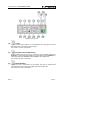
Figure 4.- Main keyboard
[10]
TV KEY
It allows visualising the image of TV corresponding to the input signal as well as
data relative to the reception of the video signal.
Key number 1 to enter numeric data.
[11]
EXTERNAL UNITS POWER SUPPLY
Enables selecting the power supply to the external units. Available voltages are:
External, 5 V, 13 V, 15 V, 18 V and 24 V for the terrestrial band and External, 5 V,
13 V, 15 V, 18 V, 13 V + 22 kHz and 18 V + 22 kHz for the satellite band.
Key number 2 to enter numeric data.
[12]
MEASUREMENTS
Enables the type of measurement to be selected. The types of measurements
available depend on the band, the standard and the operating mode.
Key number 3 to enter numeric data.
09/2011
Page 21
USER’S MANUAL. TV EXPLORER HD DTMB
[13]
SPECTRUM/TV
Allows switching between any previous operating mode and the Spectrum
Analyser mode and vice versa.
Key number 4 to enter numeric data.
[14]
SATELLITE/TERRESTRIAL BAND
Allows switching between the Satellite or Terrestrial TV frequency band.
Key number 5 to enter numeric data.
[15] S
This led remains lighted when the equipment works with the frequencies and the
corresponding channels to the satellite band.
[16] T
This led remains lighted when the equipment works with the frequencies and the
corresponding channels to the terrestrial band.
[17]
MEASUREMENT CONFIGURATION
It allows the commutation between the measurement mode for Digital TV or
Analogue TV.
[18] D
This led remains lighted when the equipment works with digital signals.
[19] A
This led remains lighted when the equipment works with analogue signals.
[20]
IMAGE ADJUST
Activation of VOLUME, CONTRAST, BRIGHT, SATURATION and HUE (only for
NTSC colour system) control menus.
Key number 6 to enter numeric data.
[21]
DISEQC
(Only in satellite band). It allows adjusting configuration parameters in satellite
band.
Key number 7 to enter numeric data.
Page 22
09/2011
USER’S MANUAL. TV EXPLORER HD DTMB
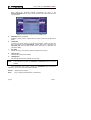
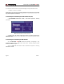
[22]
UTILITIES / PREFERENCES
It activates the Utilities menu (short pulsation):
Equipment Info.
Displays information about the instrument: Company’s
Name; Instrument’s Name; Product Number; Control
Software Version; User, that shows free disk space
(compact flash) to store data (Datalogger and channel
plans); Video, that shows free disk space to save
Transport Streams; Date and time.
Constellation
Sets the constellation diagram graph for the digital signal
on tune.
Attenuation Test
(Only terrestrial band).
Selects the function for testing signal distribution
networks in terrestrial band.
Sat IF Test
(Only satellite band).
Selects the function for testing signal distribution
networks in satellite band.
DTMB Echoes
Graphical representation of the channel response and
list of echoes detected in the signal response.
PVR
It saves or plays a video stream.
Run Datalogger
Function to automatically acquire measurements.
View Datalogger
Displays the available acquisition list.
Erase Dataloggers
Deletes an acquisition previously recorded.
Delete Channel Set
Delete the channel plan selected.
Delete Channels
Delete a channel from the active channel plan.
Insert Channels
Add a channel to the current channel plan from another
standard list of channels.
Save as:
Saves with a file name the capture screen in order to be
later processed.
Recall Constell
Recall a constellation diagram stored in memory.
Recall
Spectrogram
Recall a Spectrogram graph stored in memory.
Recall Spectrum
Recall a signal spectrum previously stored.
09/2011
Page 23
USER’S MANUAL. TV EXPLORER HD DTMB
Delete Capture
Allows to delete a screen capture file.
Delete Print Screen
It allows deleting a selected print screen.
Exit
Exit from Utilities.
It activates the Preferences menu (long pulsation):
Language
Selects the language between DEUTSCH, ENGLISH,
ESPAÑOL, FRANÇAIS, ITALIANO, CATALÀ and
PORTUGUÊS.
Beep
Activates (ON) / deactivates (OFF) the beeper.
Skin
Sets the display skin. It is possible to add new types
through the USB port.
Light Sensor
It activates a light sensor to automatically adjust the
display contrast and brightness. Options are: High
contrast (with high luminosity), Low contrast (with low
luminosity) and AUTO.
Power measure:
It allows you to select between two options to measure
power: Integrated or extrapolated. The integrated
method performs a calculation based on the true RMS
value for any type of signal. The extrapolated method is
an approximation according to power measurements
already taken.
Min. Ter. Power
Sets the minimum power for a terrestrial digital signal to
be identified.
Min. Ter. Level
Sets the minimum level for a terrestrial analogue signal
to be identified.
Min. Sat. Power
Sets the minimum power for a satellite digital signal to
be identified.
C/N
Defines the C/N measuring method between Auto or
Reference Noise (Manual), used to determine the
frequency where noise level will be measured in the
spectrum analyser mode.
Identify Timeout
Sets the maximum time that the equipment will carry out
the identification of a channel unknown before going to
the next one.
Sat Band
(Only satellite band).
Selects the C-band or Ku-band for tuning satellite
signals.
Page 24
09/2011
USER’S MANUAL. TV EXPLORER HD DTMB
Auto Power Off
Activates the automatic power off mode.
Time Power Off
Select the power off timeout from 1 to 120 minutes.
Terrestrial Units
Select the measurements units for terrestrial and cable:
dBµV, dBmV or dBm.
Satellite Units
Select the measurements units for satellite: dBµV, dBmV
or dBm.
Rotary Selector
Select the movement sense: CW (clockwise) or CCW
(counter clockwise).
Ref. level
It selects the most suitable range when accessing to the
spectrum analyser mode: MANUAL (defined by the user)
or AUTO (calculated by the instrument).
Transport Mode
It activates or it deactivates the automatic power off
function for transportation. So, it allows to prevent an
accidental start-up of the equipment.
Factory Reset
It recoveries the default settings (the ones the
equipment originally had). This option will remove all
acquisitions made by the user. Added channel plans are
kept.
Exit
Exit from preferences menu.
Key number 8 to enter numeric data.
[23]
ANTENNA ALIGNMENT
Tool for faster sweep antenna alignment at terrestrial and satellite bands. Displays
the measurements by means of a graph level bar.
Key number 9 to enter numeric data.
[24]
TUNING BY CHANNEL OR FREQUENCY
Switches tuning mode between channel and frequency. In channel mode the
tuning frequency is defined by the active channels table (CCIR, ...).
Key number 0 to enter numeric data.
09/2011
Page 25
USER’S MANUAL. TV EXPLORER HD DTMB
[25]
AUTO ID/ EXPLORER
Activates the automatic identification function (short pulsation):
The instrument will try to identify the signal under test.
First it recognises whether the signal is an analogue channel or a digital one.
If the channel is analogue, it determines the television standard of the signal
detected.
When the signal is digital, it analyses the modulation type: DTMB / DVB-C /
DVB-S / DVB-S2 and all the associated; parameters such as the carriers 2k8k, the symbol rate, the code rate, etc and it tries to lock to the signal.
In the spectrum analyser and measurements mode, it appears on screen the
name of the network and the orbital position (only in satellite band).
Activates the band exploration function (long pulsation):
The meter explores the entire frequency band to identify the analogue and
digital channels present.
30
Figure 5.- Top panel view.
Page 26
09/2011
USER’S MANUAL. TV EXPLORER HD DTMB
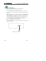
RF signal input
[30] RF
Maximum level 130 dBµV. Universal connector for F/F or F/BNC adapter, with
input impedance of 75 Ω.
ATTENTION
10 dB ATT
Use the 10 dB attenuator (AT-010) to protect the RF
[30] input whenever
the input signal level is greater than 130 dBµV (1 V) or when suspecting about
intermodulation problems.
This accessory allows DC voltages to pass when powering external units as
LNB and amplifiers.
Figure 6.- Connecting external attenuator on RF input [30].
ATTENTION
Note the importance to protect the RF
[30] input signal with an
accessory to block the AC voltages used in CATV cables (needed to feed the
amplifiers) and remote control.
09/2011
Page 27
USER’S MANUAL. TV EXPLORER HD DTMB
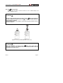
34
35
36
31 32
33
Figure 7.- Lateral panel elements.
[31] RESET button
Enables the user to restart the instrument if there is any irregularity when
operating.
[32] External 12 V power supply input
[33] Loudspeaker
[34] Fan
[35] SCART connector
[36] Transport belt hook
Figure 8.- Rear panel view.
Page 28
09/2011
USER’S MANUAL. TV EXPLORER HD DTMB
[38] CAM module extraction button
Press it to remove a CAM module inserted into the connection socket [38].
[39] HDMI Connector (High-Definition Multi-media Interface).
[40] USB Connector
It enables the communication with a PC, and to download dataloggers and
channel plans.
[41] CAM module connection socket
Enables the conditional access (desencryption) of encoded digital TV signals in
agreement with DVB-CI (Common Interface) recommendation.
[42] TS-ASI Output.
[43] TS-ASI Input.
5.2
Adjustment of Volume and Monitor Parameters
Repeatedly pressing the
[20] key sequentially activates the VOLUME,
CONTRAST, BRIGHTNESS, SATURATION and HUE control menus (this last only for
NTSC colour system). On activation of a menu for a specific parameter the screen
displays a horizontal bar whose length is proportional to the parameter level, to modify
this value simply turn the rotary selector
value press the rotary selector
5.3
[1]. To exit the menu and validate the new
[1].
Selecting the Operation Mode: TV / Spectrum Analyser /
Measurements
The TV EXPLORER HD DTMB has three basic operation modes: TV, Spectrum
Analyser and Measurements. To switch from TV operation mode to the Spectrum
Analyser press
[13] key. To switch to the Measurements mode press
[12] key.
In the TV operation mode the demodulated television signal is shown on-screen;
this is the default operation mode, various functions can be selected, as shown in the
following paragraphs.
In the Spectrum Analyser operation mode the screen displays the spectrum of
the active band (terrestrial or satellite). The span and the reference level.
In the Measurement mode the screen shows the available measurements
according to the type of signal selected.
09/2011
Page 29
USER’S MANUAL. TV EXPLORER HD DTMB
5.4
Channel Tuning / Frequency Tuning
Pressing
[24] key the EXPLORER switches from frequency tuning to channel
tuning and back again.
[1] sequentially tunes the
In channel tuning mode turning the rotary selector
channels defined in the active channels table. When turning it clockwise frequency
increases while turning it anticlockwise frequency decreases.
In frequency tuning mode there are two ways of tuning:
1. Turning the rotary selector
[1].
Turning the rotary selector
[1] selects the desired frequency (tuning is
continuous from 5 to 1000 MHz and from 950 to 2150 MHz). When turning it
clockwise frequency increases while turning it anticlockwise frequency
decreases.
2. Using the keyboard.
[1] (the frequency listing will disappear and will
Press the rotary selector
appear on the upper left corner of screen the keyboard symbol of manual data
), next enter the frequency value in MHz using the numeric
entry
keyboard. The TV EXPLORER HD DTMB will calculate the tuneable
frequency closest to the entered value and then display it on-screen.
5.5
Automatic Transmission Search
[25] key search starts over the active channel plan. When
Holding pressed the
tuning a channel the instrument tries to identify it and save it with the configuration. If the
identification is not possible the channel is removed from list. As a result obtains a new
channel plan that only contains the channels that have been identified.
5.6
Selecting the measurement configuration: Analogue/ Digital signal
Measuring the characteristics of a channel depends, in the first place, on the type
of modulation: analogue or digital.
Page 30
09/2011
USER’S MANUAL. TV EXPLORER HD DTMB
Use key
[17] to switch between analogue and digital channels. Press the
[17] key to show the measurements CONFIGURATION menu and select the
Signal option by turning and pressing the rotary selector
[1]. The Signal option
allows setting the type of signal to measure. When switching to a new type, the
TV EXPLORER HD DTMB activates the last measurement configuration used for that
type of signal.
5.7
External Units Power Supply
The TV EXPLORER HD DTMB can supply the voltage needed to power the
external units (antenna preamplifiers, in the case of terrestrial TV, LNB in the case of
satellite TV, or IF simulators).
In order to select the supply voltage of the external units, press
[11] key, and
the screen will display a functions menu labelled EXT. SUPPLY listing the choice of
[1] to
voltages (which will depend on the band being used). Turn the rotary selector
the desired voltage and press to activate it. The following table shows the choice of
supply voltages:
Band
Powering voltages
SATELLITE
Output: Enabled / Disabled
External
5V
13 V
15 V
18 V
24 V
13 V + 22 kHz
18 V + 22 kHz
Output: Enabled / Disabled
External
5 V
13 V
15 V
18 V
24 V
TERRESTRIAL
MATV (Master Antenna Television)
Table 3.- External units powering voltages.
When the OUTPUT is enabled, the equipment puts at the output the voltage
selected by the user. When the OUTPUT is disabled it does not apply the voltage at the
output but it works like it was.
09/2011
Page 31
USER’S MANUAL. TV EXPLORER HD DTMB
In the External power supply mode is the unit powering the amplifiers before the
antenna (terrestrial television) or the satellite TV receiver (house-hold or community)
also powers the external units.
The DRAIN [3] indicator lights when current is flowing to the external unit. If any
kind of problem occurs (e.g., a short circuit), an error message appears on the monitor
('SUPPLY SHORT'), the acoustic indicator will be heard and the instrument will cease to
supply power. The TV EXPLORER HD DTMB does not return to its normal operating
state until the problem has been solved, during this time it verifies every three seconds
the persistence of the problem warning with an acoustic signal.
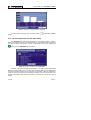
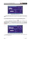
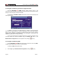
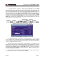
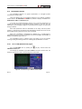
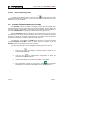
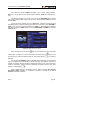
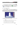
5.8
Automatic signal identification function (AUTO ID)
The TV EXPLORER HD DTMB allows automatically identifying TV signals,
according to the established configuration, which are presents in the channel or tuned
frequency. In order to activate this function must once press
[25] key. Specially
useful, is to combine this process with the spectrum monitoring
[13], so that after
locating the marker on the levels susceptible to contain a transmission, and activating
later the process of automatic identification in order to identify the present signal.
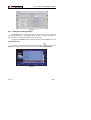
Figure 9.- Signal automatic identification screen. AUTO ID.
First it recognises whether the signal is an analogue channel or a digital one. If the
channel is analogue, it determines the television standard of the signal. When the signal
is digital (DVB), it analyses for each modulation type QAM / QPSK / 8PSK / DTMB all
the associated parameters such as the modulation system: carriers, symbol rate, code
rate, etc.,. and determines the value of the signals under test.
If the AUTO ID function is launched in the spectrum analyser mode, the name of
the network will appear temporarily on screen (it also appears in the measurement
display). In case of working in the satellite band the orbital position appears as well.
Page 32
09/2011
USER’S MANUAL. TV EXPLORER HD DTMB
While performing automatic identification may be the equipment keeps detecting
the NETWORK ID for a long time. During this process, the CANCEL button switches to
SKIP, which allows by passing the NETWORK ID without losing the other parameters of
the autodetection.
Whenever the process detects new parameters for a channel or frequency will
create a new channel plan containing the detected information.
NOTE: The
icon in the upper corner of a digital measurement screen states
that the signal level is higher than the minimum threshold (see the
PREFERENCES menu) but demodulator cannot lock it maybe due to some
wrong configuration parameter.
In such case, the user must press AUTO ID
[25] key.
NOTE: In the case that is desired to explore or identify DVB-C signals will be
necessary to select previously a DVB-C standard as digital signal identifier
by means of
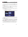
5.9
[22] PREFERENCES menu.
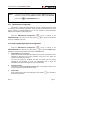
Channel plans
The signal automatic identification process as much as the exploration of the
frequency spectrum could yield the generation of new customised channel plans relative
to the usual work locations of the meter equipment.
In this way the characterisation of the band will be faster and easier when causing
that the equipment only analyses a shorter set of channels.
Whenever a new process of exploration is activated, the TV EXPLORER HD
DTMB analyses all the present channels in the active channel plan, which acts as
pattern channel plan specified by means of the option CHANNEL SET from
configuration measurement menu: CONFIGURATION
[17].
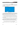
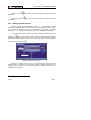
If during exploration or automatic identification process the TV EXPLORER HD
DTMB detects new parameters for some channel or frequency a new list will be
generated with the information updated and will be saved with the name of the original
channel plan followed by the extension: _0x. (See the following Figure).
09/2011
Page 33
USER’S MANUAL. TV EXPLORER HD DTMB
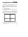
CCIR:
02
03
04 S01 S02 S03
67
68
69
STD CHANNEL PLAN
EXPLORER
CCIR_01:
CCIR:
02
02
04 S03 S10
03
65
68
04 S01 S02 S03
67
+ PARAMS. NEW CHANNEL PLAN
68
69
STD CHANNEL PLAN
AUTO ID
CCIR_01:
02
03
04 S01
68
69
+ PARAMS. CH04
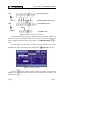
Figure 10.- New channel plan generation process.
Those channels that have not been identified during the exploration process are
removed from the new generated channel plan. The user can save this table in the
memory, modify its name and later use it by means of the CONFIGURATION
menu.
[17]
Also can delete any channel list, or remove and add channels from another
standard list by means of the editing options offered by the
UTILITIES [22] menu.
Figure 11.- Channel plans listing.
Keep the
[24] key pressed in order to accede to the listing of channel plans
available in the instrument and later select the current channel plan by means of the
rotary selector
Page 34
[1].
09/2011
USER’S MANUAL. TV EXPLORER HD DTMB
The TV EXPLORER HD DTMB allows directly changing the tuned channel
pertaining to the active channel plan by means of the horizontal cursors [6]
key.
From this way, once selected the channel-tuning field
[10]
and MEASUREMENTS
entire active channel list.
NOTE:
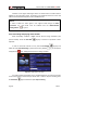
5.10
[24] and in the TV
[12] operation modes is possible to check cyclically the
The icon
in the upper corner of the screen indicates that the
equipment is carrying out an internal operation and user must wait to
complete it.
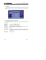
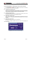
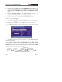
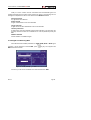
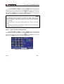
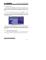
Acquisition function (DATALOGGER)
The Datalogger function allows the user to carry out and store measurements in a
fully automatic way. It can store for each acquisition the measurements made in different
points of the installation. The measurements made are relevant to the current analogue
or digital channel, in the active channel plan.
[22] menu and
To select the Datalogger function, activate the UTILITIES
select the RUN DATALOGGER option. Later, by turning the rotary selector [1] select a
previously stored acquisition or a NEW DATALOGGER.
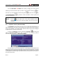
Figure 12.- DATALOGGER screen.
During analogue channel measuring process, a percentage counter appears at the
bottom of the screen showing the percentage of channel measurement done. In the case
of digital channels, appears a timer showing time left to finish in seconds. At the top left
corner appears the channel being measured followed by the total amount of channels in
the current channel plan.
09/2011
Page 35
USER’S MANUAL. TV EXPLORER HD DTMB
In order to select the different fields on the screen, press the cursors
and then edit by pressing the rotary selector
[6] key
[1].
After selecting the START field the instrument begins to carry out the available
measurements automatically. Once completed, the process will be ready to repeat again
(for example, for a new test point), or view measured data by turning the rotary selector
[1], or store the information in memory (SAVE) or exit from this acquisition (EXIT).
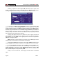
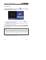
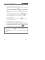
5.10.1 DATALOGGER for Attenuation and IF SAT tests
The TV EXPLORER HD DTMB allows to make measurement acquisitions while
executing an Attenuation test at terrestrial band or an IF SAT test at satellite band (see
section “5.11 Verification of distribution networks”).
For it, one of these tests should be activated previously as the following figure
shows.
Figure 13.- Attenuation Test. Terrestrial band.
In order to make the automatic acquisition of these measurements, select it from
[22] key, and activating the RUN DATALOGGER
UTILITIES menu by pressing the
option, and later the NEW DATALOGGER option. In the CHANNEL SET field will
appear the type of test that the instrument is going to store automatically.
Page 36
09/2011
USER’S MANUAL. TV EXPLORER HD DTMB
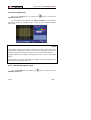
Figure 14.- Datalogger screen for Attenuation test frequencies.
Once the START option is selected the instrument will capture all test values
corresponding to the three pilot frequencies in the active band. When measuring is
completed, it will offer the options to store data or to start a new acquisition.
Figure 15.- End of data acquisition.
NOTE:
In order to select the function (Attenuation test or IF SAT test) might
be necessary to switch the frequency band between Terrestrial or
Satellite by means of the front panel
09/2011
key [14].
Page 37
USER’S MANUAL. TV EXPLORER HD DTMB
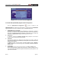
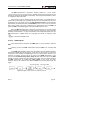
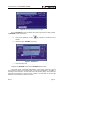
5.11
Verification of distribution networks
(SAT IF Test / Attenuation Test)
This application allows to verify easily the TCI features (Telecommunications
Common Infrastructures) before the antennas and head-end devices are operative. The
procedure allows to evaluate the frequency response of a whole TV signals distribution
network by means of two steps:
NOTE: For this application the use of PROMAX RP-050, RP-080, RP-110 or
RP-250 signal generators are required, for which they have been specially
designed. If you use a generator that emits not modulated carriers, this may
cause a slight uncalibration during the SAT IF TEST.
1.- CALIBRATION
Connect the generator directly to the TV EXPLORER HD DTMB using the BNC-F
adapter.
Power the signal generators of the RP PROMAX family through the
TV EXPLORER HD DTMB or an external power supply. To set the External supply
function (see section '5.7 External Units Power Supply') press the
rotary selector
[11] key, and the
[1] to set a voltage of 13 V.
[22] menu for SAT
Finally, select the SAT IF TEST application on UTILITIES
band, or the ATTENUATION TEST for terrestrial band, connect the generator to the
point where the antenna will be connected (signal source).
[17] key to see on screen the measurement CONFIGURATION. By
Press the
means of the Threshold Attenuation option is possible to adjust the maximum difference
between the pilots reference level from 5 to 50 dBmV.
[6] key, select the Calibrate function
Later, by means of the horizontal cursors
(see the following figure). Wait for some seconds until the calibration process for three
pilots is completed: MEASURING REF. is indicated on screen while this process is in
progress.
Page 38
09/2011
USER’S MANUAL. TV EXPLORER HD DTMB
Figure 16.- SAT IF Test. Satellite band.
The calibration process must be carried out over the point of the installation which
is taken as reference, i.e. usually the headend. During this process is determined the
number of pilot frequencies to check, from one to three, in addition to the reference level
for pilots. In order to determine the number of pilots, the equipment takes the higher
found level and verifies that the other pilots have a non lower level to the reference one
plus the defined threshold level. If the pilot agrees this condition it will show on screen.
The user can also define the pilot frequencies:
[17] to show on screen the CONFIGURATION menu of the
Press the key
measure. The PILOTS function allows you to set pilot signals manually. To do this, using
[1] select that function and change it to MANUAL. You will see a
the rotary selector
menu where you can set the frequency of each of the 3 pilot signals. If you want to return
to the automatic generation of pilot signals, change back PILOTS function to AUTO.
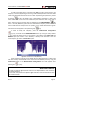
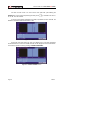
2.- MEASUREMENT OF THREE PILOTS THROUGH THE NETWORK
Once TV EXPLORER HD DTMB has been calibrated, start to make level
measurements in the different distribution outlets using the TV EXPLORER HD
DTMB. On the screen will appear the attenuation values for the three pilot
frequencies measured in the outlet plate (see the following figure).
09/2011
Page 39
USER’S MANUAL. TV EXPLORER HD DTMB
Figure 17.- Attenuation measurements in an outlet plate.
In order to finish measuring, press the rotary selector
option.
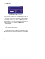
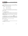
5.12
[1] and select the (EXIT)
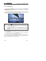
Spectrum exploration function (EXPLORER)
The Exploration function allows exploring the full frequency band in order to
identify the analogue channels and digital presents, in agreement with the configuration
set, over the active channel plan. In order to activate the function hold pressed the
[25] key until the EXPLORER screen appears.
Figure 18.- Spectrum exploration screen. EXPLORER.
When the instrument completes the exploration, a new channel plan is generated
based on the active channel plan. This new channel plan contains only the channels that
have been identified and the rest are removed. The equipment offers the possibility of
saving in memory the channel plan generated to use later. If the new channel plan is not
saved it will remain active until the instrument is powered off or some other plan is
loaded.
Page 40
09/2011
USER’S MANUAL. TV EXPLORER HD DTMB
NOTE:
In the case that is desired to explore or identify DVB-C signals will be
necessary to select previously DVB-C standard as digital signal identifier
by means of
5.13
[22] PREFERENCES menu.
Measurements configuration
With the aim of taking the measurements of all types of signals some times could
be necessary that user enters parameters relative to particular characteristics of these
signals, whether an automatic detection has not been possible, or these parameters
differ from the standard corresponding ones.
Press the Measurements Configuration
CONFIGURATION menu and turn the rotary selector
which are modifiable by the user.
[17] key to access to the
[1] to access to parameters
5.13.1 DVB-C (QAM) Digital Channel Configuration
Press the Measurements Configuration
[17] key to access to the
CONFIGURATION menu and turn the rotary selector
[1] to access the QAM signals
parameters, which can be defined by user and are described below:
1)
Channel BW (channel bandwidth)
Enables the channel bandwidth to be selected up to 9.2 MHz. The selection of this
parameter is essential for the correct operation of the tuner, as it affects the
frequency separation of the carriers.
The user can modify the bandwidth and then the symbol rate will change
according to the bandwidth, but once the demodulator locks a signal, the
bandwidth will change according to the symbol rate detected.
2)
Spectral inversion
If necessary, activate the Spectral inversion (On). If the spectral inversion is not
correctly selected, reception will not be correct.
3)
Symbol Rate
When selecting this function and pressing the rotary selector
choose the symbol rate.
09/2011
[1] is possible to
Page 41
USER’S MANUAL. TV EXPLORER HD DTMB
4)
Modulation
It defines the modulation type. When selecting this function and turn the rotary
[1] to choose one of the following modulations: 16, 32, 64, 128 and
selector
256.
Figure 19.- Screen of mesurement configuration (QAM signals).
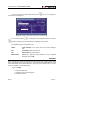
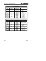
5.13.2 DTMB Digital Channel Configuration
This configuration menu shows, the value of the signal parameters detected
automatically:
Channel BW
Fixed to 8 MHz in DTMB configuration.
Code Rate
FEC protection ratio: 0.40, 0.60, 0.80.
Constellation
Carriers modulation. It also defines the system noise immunity.
QAM4NR, QAM4, QAM16, QAM32, QAM64.
Time Interleaver
240, 720.
Frame Header
The frame header corresponds to the dead time between symbols,
its purpose is to permit a connect reception in multi-path situation:
420, 595, 945.
Carrier Mode:
Multiple or Single.
Page 42
09/2011
USER’S MANUAL. TV EXPLORER HD DTMB
Figure 20.- Screen of mesurement configuration (DTMB signals).
5.13.3 DVB-S/S2 (QPSK/8PSK) Digital Channel Configuration
Press the Measurements Configuration
[17] key to access to the
[1] to access the QPSK/8PSK
CONFIGURATION menu and turn the rotary selector
signals parameters which can be defined by user and are described below:
1)
Channel BW (channel bandwidth)
Enables the channel bandwidth to be selected over a range from 1.3 MHz to
60.75 MHz. The selection of this parameter is essential for the correct operation of
the tuner, as it affects the frequency separation of the carriers. If you change the
bandwidth the Symbol Rate changes proportionally and vice versa.
2)
Spectral Inv
If necessary, activate the Spectral inversion (On). Reception will be bad if
spectral inversion has been incorrectly selected.
3)
Code Rate
Also known as Viterbi ratio. It defines the ratio between the number of data bits
and actual transmission bits (the difference corresponds to the control bits for error
detection and correction).
In DVB-S it permits to choose between 1/2, 2/3, 3/4, 5/6 and 7/8. In DVB-S2 it
permits to choose one of the following values: 1/4, 1/3, 2/5, 1/2, 3/5, 2/3, 3/4, 4/5,
5/6, 8/9 y 9/10.
4)
Symbol Rate
It is possible to choose over the following values: from 1000 to 45000 kbauds.
When selecting the option appears the current value, in order to modify it enter a
new value through keyboard when appears the data enter symbol appears on the
upper left corner screen.
09/2011
Page 43
USER’S MANUAL. TV EXPLORER HD DTMB
When altering this parameter modifies automatically the value of the
Channel Bandwidth and vice versa, due to the relation that exists between these
two parameters.
Figure 21.- Mesurement configuration screen (QPSK signals).
5)
Modulations (Only in DVB-S2)
Modulation used by carriers. It defines also the system noise immunity (QPSK and
8PSK).
6)
Polarization
It affects to the signal reception in the SAT band (satellite). It allows to select the
signal polarisation among Vertical/Right (vertical and circular clockwise) and
Horizontal/ Left (horizontal and circular counter clockwise) or, to deactivate the
polarization (OFF).
7)
Sat Band
Selects the High or Low frequency band for satellite channel tuning.
8)
LNB Low Osc.
Sets the LNB low band local oscillator.
9)
LNB High Osc.
Sets the LNB high band local oscillator (up to 25 GHz).
NOTE:
In the channel tuning mode the Polarization and Sat Band options cannot be
modified.
This configuration menu shows, besides the QPSK/8PSK signal parameters
selected by user, all the values automatically detected:
Roll Off
Nyquist filter roll-off factor.
Pilots
(Only in DVB-S2) Pilots detection in transmission.
Page 44
09/2011
USER’S MANUAL. TV EXPLORER HD DTMB
IMPORTANT REMARK
DVB channels tuning may require an adjusting process. It is recommended to follow
next procedure:
1.
From the spectrum analyser mode
frequency.
[13], tune the channel at its central
2.
Switch to Measurements mode
3.
If in the lower line of the screen does not appear MPEG-2 message (and
consequently BER is unacceptable), by turning the rotary selector deviate the
tuning frequency until MPEG-2 message appears. Finally tune channel again
to minimize the frequency deviation which optimises the BER and therefore
minimize the BER.
[12], measurement selection.
If it is not possible to detect any MPEG-2 channel, make sure that digital signal
parameters are correctly defined.
5.14
Selecting the Measurements
The types of measurements available depend on the operating band (terrestrial or
satellite) and the type of signals (analogue or digital).
Terrestrial band - Analogue channels:
Level
Level measurement of the currently tuned carrier.
Video / Audio
Video carrier to audio carrier ratio.
C/N
Ratio between the modulated signal power and the equivalent
noise power for a same bandwidth. (according to TV standard)
FM Deviation
Measure the frequency peak deviation for any modulated
analogue carrier in FM.
Terrestrial band - Digital channels (DVB-C, DTMB and ITU-T J.83/B):
Channel power
Channel power is measured assuming that power spectral
density is uniform throughout channel bandwidth.
To measure it correctly it is indispensable to define the
Channel BW.
C/N
Out-channel measurement. Noise level is measured at fnoise=
ftuning ± ½*Channel BW. To measure it correctly digital channel
must be tuned at its central frequency.
09/2011
Page 45
USER’S MANUAL. TV EXPLORER HD DTMB
MER
Modulation error ratio with noise margin indication.
CBER
(only for DVB-C and
ITU-T J.83/B)
BER measurement (Bit error rate) for the digital signal before
error correction (BER before FEC).
LBER
(only for DTMB)
BER measurement (Bit error rate) for the digital signal after error
correction (BER after LDPC).
Satellite band - Analogue channels
Level
Level measurement of the currently tuned carrier.
C/N
Ratio between the modulated signal power and the equivalent
noise power for a same bandwidth.
Satellite band - Digital channels (DVB-S/S2):
Channel Power
Automatic method.
C/N
Ratio between the modulated signal power and the equivalent
noise power for a same bandwidth.
MER
Modulation Error Ratio. Complementary measurement of the
Noise Margin for DVB-S and the Link Margin for DVB-S2.
CBER
The BER measurement (Bit error rate) for the digital signal
before error correction (BER before FEC).
VBER
(Only for DVB-S) The BER measurement (Bit error rate) for the
digital signal after error correction (BER after Viterbi).
LBER
(Only for DVB-S2) The BER measurement (Bit error rate) for the
digital signal after error correction (BER after LDPC).
In order to change the measurement highlighted, press the
[12] key. On the
monitor will appear cyclically all the measures available for the signal on tune.
5.14.1 Analogue TV: Measuring the Video Carrier Level
In the measurement mode of analogue signals, the TV EXPLORER HD DTMB,
monitor can work as an analogue indicator of level representing the signal present in the
input.
Page 46
09/2011
USER’S MANUAL. TV EXPLORER HD DTMB
In order to change the measurement mode press
screen like the following one:
[12] key, it will appear a
Figure 22.- Analogue signal level measurement in terrestrial band.
Turn the rotary selector
[1] to change the tuning channel/frequency. Press the
[12] key to select the type of measurement to highlight on the monitor.
The available types of measurements are:
LEVEL:
Level indication on the upper part of the screen (analogue
bar).
C/N:
Carrier/Noise ratio measurement.
V/A:
Video/Audio ratio measurement.
FM Deviation:
Measure the frequency peak deviation for any modulated
analogue carrier in FM.
WARNING
When at the RF input appear an important number of carriers with a high level the tuning
circuit may become out of control, giving as a result wrong level measurements. To be
able to determinate the equivalent level of a carrier group (with similar levels) at the RF
input, it is possible to use the expression:
Lt=L + 10 log N
Lt: equivalent total level
L: average level of the carriers group
N: number of carriers
09/2011
Page 47
USER’S MANUAL. TV EXPLORER HD DTMB
So, if there are ten carriers with a level around 90 dBµV, their equivalent level will be:
90 dBµV + 10 log 10 = 100 dBµV
Observe that in this case, loss of tuning by overload of the RF input may occur besides
other effects such as tuner saturation and generation of intermodulation products that
may mask the spectrum visualization.
5.14.2 Analogue TV: Measuring the Video / Audio ratio (V/A)
In the Audio/Video measurement mode, on the screen appears the following
information:
Figure 23.- Measurement of the video/audio ratio.
In addition to the video carrier / audio carrier level ratio (16.2 dB in previous figure)
it also shows the frequency or channel, depending on the tuning mode selected, and the
Carrier/Noise ratio.
5.14.3 Analogue TV: Measuring the FM deviation
The TV EXPLORER HD DTMB measure the deviation in frequency of any
modulated analogue carrier in FM. This function allows visualising frequency peak
deviation for FM carrier signals.
Once this DESV FM measurement mode is activated will appear the following
information on screen:
Page 48
09/2011
USER’S MANUAL. TV EXPLORER HD DTMB
Figure 24.- FM carrier peak deviation.
On the screen appears the deviation peaks in order to observe if they are within a
suitable range limit valid for both, the receiver and the transmitter in the transmitting
system.
5.14.4 Analogue FM: Measuring the Level and demodulating signal
Press the Measurement Configuration
[17] key to accede to the
CONFIGURATION menu and turn the rotary selector
[1] in order to select the
analogue FM signal. In the analogue FM measurement mode, the TV EXPLORER
HD DTMB display works like an analogue level indicator showing the signal level present
in the input.
Figure 25.- FM analogue signal measurement.
The instrument also demodulates the FM carrier (radio) and allows to listen sound
through the loudspeaker [33].
09/2011
Page 49
USER’S MANUAL. TV EXPLORER HD DTMB
5.14.5 Analogue/Digital TV: Measuring the Carrier / Noise ratio (C/N).
The TV EXPLORER HD DTMB carries out C/N ratio measurement in four different
ways, according to the carrier type and the used band:
A)
Terrestrial band, analogue carrier
Carrier level is measured using a quasi-peak detector (230 kHz BW). Noise level is
measured with an average detector and corrected to refer it to channel equivalent
noise bandwidth (according to the definition of the selected standard).
B)
Terrestrial band, digital carrier
Both measurements are done with an average detector (230 kHz) and the same
corrections are introduced on them (bandwidth corrections).
C)
Satellite band, analogue carrier
Carrier level is measured using a quasi-peak detector (4 MHz BW). Noise level is
measured with an average detector (230 kHz) and corrected to refer it to channel
bandwidth.
D)
Satellite band, digital carrier
Equivalent to case B but now using the 4 MHz BW filter.
On selecting the Carrier / Noise measurement mode the screen displays the
following information:
Figure 26.- Carrier-to-noise ratio measurement (C/N).
Page 50
09/2011
USER’S MANUAL. TV EXPLORER HD DTMB
As well as the video carrier / noise level ratio (C/N) (41.0 dB in previous figure), the
frequency or channel (depending on the tuning mode selected) and the level of the video
carrier and video/audio ratio are also shown. When representing the spectrum by means
[13] key, the NOISE cursor is automatically positioned to a side of the
of pressing
carrier tuned. That is, the cursor will indicate the point where the value of the noise is
[22]
lower, whenever the C/N (AUTO) option is selected from the PREFERENCES
menu. If the C/N (MANUAL) option has been activated the frequency where noise level
will be measured will correspond to the position of the vertical discontinuous greencoloured cursor that appears in the spectrum graph
[13].
In order to modify this frequency, press the measurement configuration
[17] key, to accede to the CONFIGURATION menu. By turning the rotary selector
[1], locate the NOISE cursor on the position of the marker using NOISE FREQ. TO
MARKER option (see section “5.16.1 Markers”) or directly enter the value of the new
noise frequency by means of NOISE FREQ option.
Figure 27.- NOISE cursor. C/N (MANUAL).
When measuring channels in the satellite band or digital channels, to measure the
C/N ratio correctly, the bandwidth of the channel must be defined previously, using the
Channel BW option on the Measurements Configuration menu that appears when
pressing the
[17] key.
IMPORTANT REMARK
In order to measure digital channel C/N ratio it is indispensable to tune channel at
its central frequency.
In the case of the presence of adjacent digital channels, these could mask the noise
level measurement.
09/2011
Page 51
USER’S MANUAL. TV EXPLORER HD DTMB
5.14.6 Digital TV: Measuring the Power of Digital Channels
The TV EXPLORER HD DTMB measures digital channel power in the
measurement filter bandwidth and estimates total channel power assuming that spectral
density is uniform throughout channel bandwidth.
On selecting the CHANNEL POWER measurement mode, the screen displays the
following information:
Figure 28.- Digital channel power measurement.
In addition to the power of the digital channel (77.4 dBµV in previous figure) this
also shows the tuning frequency or channel, depending on the tuning mode selected,
and the offset frequency to calculate the digital channel power and the deviation
frequency of the central tuning calculated by the demodulator, measurement that
indicates the adjustment in the channel tuning.
For the power measurement of a digital channel to be correct it is essential to have
previously defined the channel bandwidth using the Channel BW option, in the
Measurements Configuration menu that appears when pressing
[17] key.
5.14.7 Digital TV: Measuring BER
The TV EXPLORER HD DTMB offers three ways to measure the error rate (BER)
of digital signals depending on the type of used modulation.
To select the BER measurement mode:
1)
Select digital signals Measurements Configuration pressing
Page 52
[17] key.
09/2011
USER’S MANUAL. TV EXPLORER HD DTMB
2)
Select by means of Signal option from CONFIGURATION menu: DVB-C for the
measurement of QAM modulated signals, DTMB for the measurement of DTMB
modulated signals or DVB-S/S2 for the measurement of QPSK/8PSK modulated
signals.
3)
Enter the parameters relative to the digital signal which appear in the
measurement CONFIGURATION menu, as described previously.
4)
Select the option to exit from measurements CONFIGURATION menu.
5.14.7.1
ITU-T J.83/B signals
Once determined the parameters of QAM Annex-B signal, it will be possible to
[12] key until the BER measurement display appears.
measure BER, press the
In the BER measurement mode, the monitor will show a display like the following
one:
Figure 29.- Screen of BER measurement of QAM Annex-B signals.
The BER measurement before error correction is shown: BER before FEC
(Forward Error Correction).
In a digital reception system for cable signals, after the QAM Annex-B
demodulator an error correction method called Reed-Solomon is applied (see following
Figure). Obviously, the error rate after the corrector is lower to the error rate at the QAM
Annex-B decoder output. This is the reason because this screen provides the BER
measurement before FEC (Forward Error Correction).
BER before FEC
TUNER
A/D
J.83/B QAM
DEMOD.
REED-SOLOMON
Figure 30.- Digital reception system via cable.
09/2011
Page 53
USER’S MANUAL. TV EXPLORER HD DTMB
The BER measurement is provided in scientific notation (i.e. 1.0 E-5 means
-5
1.0x10 that is to say one wrong bit of every 100.000) and through an analogue bar (as
its length is smaller the signal quality will be better). The analogue representation is done
on a logarithmic scale (not linear).
5.14.7.2
DVB-C signals
Once determined the parameters of QAM signal, it will be possible to measure
BER, press the
[12] key until the BER measurement display appears.
In the BER measurement mode, the monitor will show a display like the following
one:
Figure 31.- DVB-C (QAM) signals BER measurement screen.
The BER measurement before error correction is shown: BER before FEC
(Forward Error Correction).
In a digital reception system for cable signals, after the QAM demodulator an error
correction method called Reed-Solomon is applied (see following Figure). Obviously,
the error rate after the corrector is lower to the error rate at the QAM decoder output.
This is the reason because this screen provides the BER measurement before FEC
(Forward Error Correction).
Figure 32.- Digital reception system via cable.
Page 54
09/2011
USER’S MANUAL. TV EXPLORER HD DTMB
The BER measurement is provided in scientific notation (i.e. 1.0 E-5 means
-5
1.0x10 that is to say one wrong bit of every 100,000) and through an analogue bar (as
its length is smaller the signal quality will be better). The analogue representation is done
on a logarithmic scale (not linear).
With the aim to have a reference about the signal quality, it is considered that a
system has a good quality when it decodes less than one non-correctable error for every
transmission hour. This border is known as QEF (Quasi-Error-Free) and it corresponds
-4
approximately to a BER before FEC of 2.0E-4 BER (2.0x10 , that is to say two incorrect
bits of every 10,000). This value is marked on the measurement bar of the BER and
therefore, BER for acceptable signals must be at the left side of this mark.
Below the BER analogue bar it is shown the tuned frequency (or channel) and the
frequency deviation in kHz between the tuned frequency and the one, which optimises
the BER (i.e. 800.00 MHz + 1.2 kHz). This deviation must be adjusted specially from the
C/N measurement in satellite band, by tuning again the channel in frequency mode
[24], to the lower reachable value.
5.14.7.3
DTMB signals
Once determined the parameters of DTMB signal, it will be possible to measure
BER.
Following is shown the BER measurement after the LDPC error correction: the
LBER.
In a DTMB digital reception system, after the decoder other two different correction
methods are applied (see following Figure). In this case, as the previous one, each time
we apply an error corrector to a digital signal, the error rate changes, therefore if we
measure, for example, the error rate at the output of the DTMB demodulator, at the
output of the Low Density Parity Check (LDPC) decoder, and at the output of the BCH
decoder, we obtain nothing more than different error rates. This is the reason because
the BER measurement is provided after LDPC (LBER). It also shows the LDPC
iterations, which is the number ot times that the LDPC error corrector goes through the
signal.
Figure 33.- Digital reception system via terrestrial. (DVB-T2).
09/2011
Page 55
USER’S MANUAL. TV EXPLORER HD DTMB
Figure 34.- DTMB signals LBER measurement screen.
The LBER measurement is provided in scientific notation (i.e. 1.0 E-8 means 1.0 x
10-8, that is to say one incorrect bit of every 100.000.000) as its value is smaller the
signal quality will be better).
Next it is shown the tuning frequency and the frequency deviation in kHz between
the tuned frequency and the one, which optimizes the LBER. (for example Freq.:
730 MHz+ 2 kHz).
Finally it is shown a status line with information about the detected signal. The
possible messages that can appear and its meaning are showing the following list. The
messages are exposed from less to more fulfilment of the MPEG-2 standard:
No signal received
No signal has been detected.
Signal received
A signal is detected but it can not be decoded.
MPEG-2 TS DTMB
Correct detection of a MPEG-2 DTMB signal.
5.14.7.4
DVB-S/S2 signals
Once determined the parameters of QPSK signal, it will be possible to measure
BER. Following is shown the BER measurement before the error corrections: BER
before the FEC: CBER.
Page 56
09/2011
USER’S MANUAL. TV EXPLORER HD DTMB
Figure 35.- DVB-S (QPSK) signals CBER measurement screen.
In a digital reception system for satellite signals (DVB-S), after the QPSK decoder
two different correction methods are applied (see following Figure). Obviously, each time
we apply an error corrector to a digital signal, the error rate changes, therefore if we
measure in a digital satellite television system, for example, the error rate at the output of
the QPSK demodulator, at the output of the Viterbi decoder, and at the output of the
Reed-Solomon decoder, we obtain nothing more than different error rates. This is the
reason because the BER measurement is provided before FEC, after Viterbi (VBER).
Figure 36.- Digital reception system via satellite. (DVB-S)
Figure 37.- DVB-S (QPSK) signals VBER measurement screen.
09/2011
Page 57
USER’S MANUAL. TV EXPLORER HD DTMB
In a digital reception system for satellite signals (DVB-S2), after the QPSK
decoder other two different correction methods are applied (see following Figure). In this
case, as the previous one, each time we apply an error corrector to a digital signal, the
error rate changes, therefore if we measure in a digital satellite television system, for
example, the error rate at the output of the QPSK/8PSK demodulator, at the output of
the Low Density Parity Check (LDPC) decoder, and at the output of the BCH decoder,
we obtain nothing more than different error rates. This is the reason because the BER
measurement is provided after LDPC (LBER). It also shows the amount of packet errors
(PER), that is, the amount of packets receiving during the measurement time, which are
not correctable by the demodulator (WP).
Figure 38.- Digital reception system via satellite. (DVB-S2).
Figure 39.- DVB-S2 (QPSK/8PSK) signals LBER measurement screen.
The BER measurement is provided in scientific notation (i.e. 2.7 E-7 means
-7
2.7x10 , that is to say two incorrect bits of every 10,000,000) and through an analogue
bar (as its length is smaller the signal quality will be better). The analogue representation
is done on a logarithmic scale (not linear).
With the aim to have a reference about the signal quality, it is considered that a
system has a good quality when it decodes less than one non-correctable error for every
transmission hour. This border is known as QEF (Quasi-Error-Free) and it corresponds
-4
approximately to a BER after Viterbi of 2.0E-4 BER (2.0x10 ). This value is marked on
the measurement bar of the BER after Viterbi and therefore, BER for acceptable signals
must be at the left side of this mark.
Next it is shown the tuning frequency and the frequency deviation in MHz between
the tuned frequency and the one, which optimises the BER.
Page 58
09/2011
USER’S MANUAL. TV EXPLORER HD DTMB
Finally it is shown a status line with information about the detected signal. The
possible messages that can appear and its meaning are shown in the following list. The
messages are exposed from less to more fulfilment of the MPEG-2 standard:
No signal received
Any signal has been detected.
Signal received
A signal is detected but it can not be decoded.
Carrier recovered
A digital carrier has been detected but it can not be decoded.
Viterbi synchronized
A digital carrier has been detected and the Viterbi algorithm is synchronized, but
too many frames arrive with non correctable errors. It is not possible to quantify the
BER.
MPEG-2 TS DVB-S
Correct detection of a MPEG-2 signal.
5.14.8 Digital TV: Measuring MER
Once determined the suitable parameters for DTMB, QAM, QPSK or 8PSK signal
reception, it will be possible to measure MER, press
MER measurement screen.
[12] key until it appears the
Figure 40.- DTMB (COFDM) signals MER measurement screen.
First of all, you will see the modulation error ratio measurement: MER.
09/2011
Page 59
USER’S MANUAL. TV EXPLORER HD DTMB
Following, it appears the Noise Margin (NM) measurement (in the figure value
8.4 dB). It indicates a safety available margin according to the MER level measured that
allows signal degradation until arriving to the QEF (Quasi-Error-Free) limit value.
Figure 41.- DVB-S2 (QPSK/8PSK) signals MER measurement screen.
In the case of a DVB-S2 signal (QPSK/8PSK) instead of the Noise Margin (NM)
appears the measure of the Link Margin (LM); in the previous figure with a value of
2.3 dB. The LM is equivalent to the NM and indicates the distance to the QEF (generally
defined as one lost packet per hour). The LM is measured in dB and its value is equal to
the safety margin that separates us from the QEF. As bigger LM better signal quality. An
LM with a negative value means that there is no signal reception or errors are beginning
to display clearly in the video or the audio. An LM equal to 0 (zero) displays a service
and occasionally some artefacts can be observed.
Analogue and digital carriers are very different in terms of signal contents and
power distribution over the channel. They, therefore, need to be measured differently.
The modulation error ratio (MER), used in digital systems is similar to the Signal/Noise
(S/N) ratio in analogue systems.
MER represents the relation between the average power of DVB signal and the
average power of noise present in the constellation of the signals.
When measuring MER, it also shows the noise margin in DTMB, C, S and the Link
margin in DVB-S2, which indicates the distance from the QEF point at the current signal.
By example, QAM 64 demodulators require a MER greater than 23 dB to work.
Though it is preferable to have at least a 3 or 4 dB margin to compensate for any
possible degradation of the system. While QAM 256 demodulators require a MER
greater than 28 dB with margins of al least 3 dB. Normally, the maximum MER value
seen in portable analysers is of approximately 34 dB.
Finally it is shown a status line, which displays information about the detected
signal.
Page 60
09/2011
USER’S MANUAL. TV EXPLORER HD DTMB
5.15
Constellation Diagram
The constellation diagram is a graphic representation, of the digital symbols
received over a period of time.
There are different types of constellation diagrams for the different modulation
modes. With the TV EXPLORER HD DTMB it is possible to display constellations for
DTMB, DVB-C, DVB-S and DVB-S2 signals.
In the case of an ideal transmission channel, free of noise and interferences, all
symbols are recognised by the demodulator without mistakes. In this case, they are
represented in the constellation diagram as well defined points hitting in the same area
forming a clear dot.
Noise and impairments cause the demodulator to not always read the symbols
correctly. In this case the hits disperse and create different shapes that at the end will
allow to determine at a glance the type of noise in the signal
Each type of modulation is represented in a different way. A 16-QAM signal is
represented on screen by a total of 16 different zones and a 64-QAM is represented by a
diagram of 64 different areas and so on.
The constellation shows in different colours the density of hits and includes
zooming, scrolling and clearing functions for a better graph representation on screen.
5.15.1
ITU-T J.83/B (QAM-Annex B) signal
Go to the UTILITIES menu by pressing the
CONSTELLATION option.
[22] key, and then select the
For example the modulation type: ITU-T J.83/B is showed on screen. Next, the
frequency and channel number corresponding to the channel plan.
Figure 42.- Constellation Diagram. MPEG-2 TS ITU-T J.83/B.
09/2011
Page 61
USER’S MANUAL. TV EXPLORER HD DTMB
The TV EXPLORER HD DTMB also includes, a ZOOM function to enlarge graphic
representation over one single quadrant. Select the SCROLL option to move the focus
[6] key, CLEAR option to reset the
over the whole viewing area using arrow cursors
graph screen or SHARP option to increase the image clearness over a range from 0
(minimum visual persistence) to 16 (maximum visual persistence).
NOTE
The transmission quality is visualized in a qualitative way using a colour range for
the symbol density concentrated in a certain area. This colour coding goes from
black (no symbols) to red (maximum density), and runs from blue to yelllow in
ascending order.
A greater dispersion of the symbols indicates greater level of noise or worse signal
quality.
If concentration of symbols or noise appears is indicative of good carrier/noise ratio
or absence of problems as phase noise, etc.,.
5.15.1.1
Zoom, scroll and erasing functions
The TV EXPLORER HD DTMB also includes, a ZOOM function to enlarge graphic
representation over one single quadrant. Select the SCROLL option to move the focus
[6] key, CLEAR option to reset the
over the whole viewing area using arrow cursors
graph screen or SHARP option to increase the image clearness.
Figure 43.- Zoom x2 constellation diagram.
Page 62
09/2011
USER’S MANUAL. TV EXPLORER HD DTMB
5.15.2 DTMB signal
Activate the UTILITIES menu by pressing the
[22] key, and select the
CONSTELLATION option. Now, on screen will be recorded the hits due to symbols
received during the digital signal transmission.
Figure 44.- Constellation Diagram. DTMB (QAM 256) signal.
[1] and the arrow cursors
By means of the rotary selector
possible to change the frequency or channel.
[6] key, is
The DECAY option sets the visual persistence for symbol impacts on the screen in
a range from 0 (minimum) to 16 (maximum).
First appears the information about the type of modulation DTMB (QAM-256).
Next it is indicated the frequency, the channel and the carrier tuned. It is also indicated
the carrier type (data or pilot). Finally, it shows the status line (similar to the
measurement screen).
NOTE
The transmission quality is visualised in a qualitative way using a colour range for
the symbol density concentrated in a certain area. This colour coding goes from black
(no symbols), to red (maximum density), and runs from blue to yellow in ascending order.
A greater dispersion of the symbols indicates greater level of noise or worse signal
quality.
If concentration of symbols or noise appears is indicative of good carrier/noise
ratio or absence of problems as phase noise, etc.,.
09/2011
Page 63
USER’S MANUAL. TV EXPLORER HD DTMB
5.15.3 DVB-C (QAM) signal
Sets on the UTILITIES menu by pressing the
CONSTELLATION option.
[22] key, and select the
On screen appears the modulation type: DVB-C (256 QAM). Also the frequency
and channel number are indicated. Finally, it shows the type of DVB-C broadcast
network used.
Figure 45.- Constellation diagram. DVB-C (QAM 256) signal.
NOTE
The transmission quality is visualised in a qualitative way using a colour range for the
symbol density concentrated in a certain area. This colour coding goes from black (no
symbols) to red (maximum density), and runs from blue to yellow in ascending order.
A greater dispersion of the symbols indicates greater level of noise or worse signal
quality.
If concentration of symbols or noise appears is indicative of good carrier/noise ratio or
absence of problems as phase noise, etc.,.
5.15.4
DVB-S/S2 (QPSK/8PSK) signal
Go to the UTILITIES menu by pressing the
CONSTELLATION option.
Page 64
[22] key, and then select the
09/2011
USER’S MANUAL. TV EXPLORER HD DTMB
The modulation type: DVB-S (QPSK) or DVB-S2 (8PSK) is showed on screen.
Next, the frequency and channel number corresponding to the channel plan selected as
well as the satellite downlink frequency. Finally, it shows the status line (similar to the
measurement screen).
Figure 46.- Constellation Diagram. DVB-S (QPSK) signal.
When selecting a constellation diagram for DVB-S2 signals, on screen will appear
the following information:
Figure 47.- Constellation Diagram. DVB-S2 (8PSK) signal.
09/2011
Page 65
USER’S MANUAL. TV EXPLORER HD DTMB
NOTE
The transmission quality is visualised in a qualitative way using a colour range for
the symbol density concentrated in a certain area. This colour coding goes from
black (no symbols) to red (maximum density), and runs from blue to yellow in
ascending order.
A greater dispersion of the symbols indicates greater level of noise or worse signal
quality.
If concentration of symbols or noise appears is indicative of good carrier/noise ratio
or absence of problems as phase noise, etc.,.
5.16
Spectrum Analyser
The Spectrum Analyser mode allows the user to discover the signals present in
the frequency band in quickly and easily and to make measurements at the same time.
To select it press
the next figure.
[13] key. The monitor will show a picture like the one described in
Figure 48.- Spectrum analyser mode.
The horizontal lines define the signal level, the broken lines being separated a
distance equals to 10 dB. The level of the top line (70 dBµV in previous figure), named
[6] key over a range from
Reference Level, can be altered using the vertical cursors
60 dBµV to 130 dBµV by steps (from 70 dBµV to 130 dBµV in satellite band). The vertical
measurement range changes to 5 dB/div by holding pressed the lower arrow cursor key
[6] and changes to 10 dB/div by holding pressed the upper arrow cursor key
Page 66
[6].
09/2011
USER’S MANUAL. TV EXPLORER HD DTMB
The signal level for each frequency is displayed vertically, the lower frequencies
appear at the left of the screen and the higher ones at the right. The amplitude of the
lobes is calibrated. In the example in previous figure the noise level is at around 25 dBµV
and the lobe with the highest signal level (third from the right) is at 70 dBµV.
In the case that the equipment detects saturation on RF input due to an excess of
in the Spectrum Analyser mode and the icon
in
signal, it will appear the icon
the TV mode to indicate this situation. The user must increase the Reference Level in
order to activate an additional attenuator and to avoid the input saturation.
Speed of sweep can be modified for terrestrial TV signals. To that end, press
[17] MEASUREMENT CONFIGURATION. On the menu
shortly the key
"Configuration" it will appear the option "Sweep". Entering in this option you can switch
between "Fast" for a quick sweep of the spectrum or "Accurate" for a slower sweep.
This option will only appear when you're working with terrestrial TV signals, therefore the
led "T" on the front panel must be lighted.
The frequency range displayed (called span from hereon) can also be altered
[6] key. Therefore enables selecting the displayed
using the horizontal cursors
screen frequency range in Spectrum Analyser mode between Full (the entire band),
500 MHz, 200 MHz, 100 MHz, 50 MHz, 32 MHz, 16 MH and 8 MHz (the latter one only
in terrestrial band).
A vertical broken line, called marker, appears on the spectrum display to identify
the tuned frequency.
One of the applications of the TV EXPLORER HD DTMB operating as Spectrum
Analyser is in the search for the best orientation and position of the receiving antenna.
This is particularly important in UHF. Because such frequencies are involved, with
wavelengths ranging from 35 cm to 65 cm, if the antenna is shifted only a few
centimetres, the relationship between the picture, chrominance and sound carrier
frequencies change, affecting the quality of the picture in the receiver.
If there is an excess of sound carrier, tearing or 'moiré' may appear on the screen
due to the frequency beats between the sound, chrominance and the picture
frequencies.
If there is a chrominance carrier defect, then the television colour amplifier must
function at maximum gain, which could result in noise appearing all over the television
screen with points of colour that disappear when the saturation control is reduced; in an
extreme case, loss of colour may occur.
09/2011
Page 67
USER’S MANUAL. TV EXPLORER HD DTMB
5.16.1 Markers
(Only in Spectrum Analyser mode). The marker in red colour indicates the central
frequency or tuning frequency, which can be moved by means of turning the rotary
selector
[1] as well in channel as in frequency tuning mode
[24].
When monitoring a digital signal spectrum also appears two additional markers in
white colour, which indicate the bandwidth of the digital channel (See previous Figure).
If the highlighted measurement which appears on the measurement screen
corresponds to C/N, the Spectrum Analyser mode will measure the C/N ratio at the
frequency indicated by the marker and a second marker will indicate the frequency for
the noise measurement.
5.16.2 Spectrogram.
The Spectrogram is a useful tool and it has been designed to detect problems in a
wide range of frequencies. These problems could appear at any time and sporadically.
The Spectrogram function makes a graphical representation of the frequency
signal level regards to the time. Each level is represented with a different colour, the Yaxis belongs to frequency and the X-axis to time. Therefore a colour map is showed on
the display, see figure 46. Any frequency signal level could be displayed at any time
reference using the cursors or the variable knob. This tool is especially useful when a
level signal analysis is going to be processed during a long period of time. When the
process is finished the capture could be showed and any anomaly will be easily detected
at any time.
Figure 49.- Spectrogram.
Page 68
09/2011
USER’S MANUAL. TV EXPLORER HD DTMB
To access the spectrogram, first press the button
[13] to access the spectrum
analyser. Then you should set the parameters reference, span and frequency. Then
[22] and select SPECTROGRAM using the cursors or the variable knob. The
press
figure below shows the initial screen.
Figure 50.- First Screen.
On the X-axis the time variables references are showed. At the bottom right
corner, the capture elapsed time is displayed, in seconds. At the bottom center the
T.span defines the seconds that will be displayed on the screen. For example, if the
T.span is 60s, therefore the last 60s captured, will be displayed on the screen. On the
left corner the t variable is at time can be "end - time (s)" or "begin + time (s)".
The tag “end” indicates how many seconds you are from the last capture. To
select this option, go to the configuration menu and select the temporal reference “end”.
The tag “begin” indicates how many seconds you are from when starting the
capture. To select this option, go to the configuration menu and select the temporal
reference “beginning”.
On the Y-axis are placed the frequency variables. In this axis the initial and final
frequencies are showed and depend on the Spectrum Analyser configuration. For
example if the Spectrum Analyser frequency is 650 MHz and the Spam=100 MHz, the
Spectrogram will show as initial frequency 601MHz and end frequency 701MHz.
Next to the final frequency the cursor frequency and its signal level are displayed.
To move among the parameters press the cursor keys UP or DOWN.
To change a parameter, press the arrow keys LEFT or RIGHT or use the rotary
selector.
09/2011
Page 69
USER’S MANUAL. TV EXPLORER HD DTMB
5.16.2.1
Spectrogram Configuration
Before the capture begins the options must be configured. Press the key,
[17] and an option menu will be displayed.
Temporal reference
Begin:
The captured information will be showed on the display with initial reference 0 s.
In this option the screen is not updated with news acquisitions unless the cursor
is moved at the end of the capture.
Using the temporal position, the cursor can be move through the entire file and
the display will be updated according to the new temporal reference.
This option is very useful to visualize the captured information. For example if
the elapsed time is 500s and we want to show the 200s, this number must be
filled in the temporal position. The cursor will be moved to, and the screen will be
updated showing the new levels signals.
End:
Selecting this option, the cursor is related to the last acquisition time. If the
temporal reference is filled with 0 seconds, the cursor will be placed at the end of
the capture, therefore the screen always shows the last acquired data.
This option is very useful if we want to work during the capture process due to
the problems can be detected in real time and the cursor can be moved at any
temporal reference. When a temporal movement is introduced, noticed that a
negative sing is placed before the number by default. This is due to the
displayed data on the screen is captured in real time so that if we want to
analyse a previous point we should go backward in the time. For example if the
elapsed time is 500 s and we want to go to the second 200, the temporal
position t must be filled with — 300s.
Save
Introduce a name to save the file. If the name already exists a message will be
showed and the file could be overwritten or the operation cancelled.
Page 70
09/2011
USER’S MANUAL. TV EXPLORER HD DTMB
Acquisition mode
Select the different modes to capture a file:
CIRCULAR:
If this option is selected, other menu will be displayed. Choose the file duration.
The capture system stores the data in a file during the performed period of time.
When the elapsed time is higher than the file, the last captured data will be
stored. For example, if the selected file time is 1800s and the elapsed time is
36000, the file will be stored the seconds from 34200 to 36000.
BOUNDED:
If this option is selected, other menu will be displayed. Choose the file duration.
When the end of the file arrives, the capture will be stopped and stored.
CONTINUOUS:
The equipment starts the capture and it is not stopped until the user does it
manually or the equipment does not have free memory.
OSD INFO
If this option is selected, on the left edge of the screen a heading to connect each
signal level (dB) with the respective colour will be showed.
START
Select it to start the capture process.
To finalize the capture manually pres the key
[17] and select STOP.
EXIT
Select it to go to the initial display.
5.16.2.2
Recall a Spectrogram file
[22], choose RECALL SPECTROGRAM and select the file with
Press the key
the variable knob. The file will be displayed on the screen. All the file information is
available.
The saved files are stored in the folder OTHERS.
09/2011
Page 71
USER’S MANUAL. TV EXPLORER HD DTMB
5.16.2.3
Delete a Spectrogram file
[22] and select the option
To delete a Spectrogram capture, press the key
DELETE CAPTURE. Then it pops up a new menu where you should select SP/. Then
select the file you want to delete.
5.17
ECHOES and PRE-ECHOES Analyser (DTMB)
The ECHOES Analyser can detect and display echoes that may appear when
receiving simultaneously the same signal from several transmitters. Another reason that
can cause echoes is the reflection of the signal on large objects such as buildings or
mountains. PRE-ECHOES are signals received before the main signal arrives.
With the ECHOES function is possible to know the distance from where we are to
the transmitter or the object that has caused the echo. Thus, the installer can minimise
the effects of echoes on the facility. Knowing echoes, the installer is able to reposition
the antenna and therefore, reduce the effect of echoes received.
This feature is only available for DTMB signals. Therefore, you should configure
the TV EXPLORER HD DTMB in order to receive this type of signals. If not, the
ECHOES function will not appear on the menu “Utilities”.
The steps to go through to set up the digital terrestrial reception are the next:
Page 72
1.
[14] (Satellite / Terrestrial Band) to select the TV
Press the key
terrestrial frequency band.
2.
[17] (Measurement Configuration) to select the
Press the key
measurement mode for Digital TV.
3.
Check the led indicator “D” and the led indicator “T” are lighted.
4.
Enter parameters manually to lock signal or press
[25] (Automatic
Identification) for an automatic identification of the signal (Figure 47.-).
09/2011
USER’S MANUAL. TV EXPLORER HD DTMB
Figura 51.- Automatic identification of the signal.
Now, the ECHOES function is available. The steps to go through in order to select
the ECHOES function are the next:
[22] (Utilities) to access the menu
5.
Press (short pulsation) the key
Utilities.
6.
Select the option ECHOES (Figure 59.-).
Figure 52.-. ECHOES Menu.
7.
Press the rotary knob.
It appears the ECHOES screen and the ECHOES detection starts.
The screen shows a graphical representation of the echoes and a list of the six
most important echoes. The horizontal axis of the graph corresponds to the delay in
receiving an echo respect to the main path (the most powerful signal). The vertical axis
represents the attenuation in dB of the echo respect to the main path. At the top right
area there is the frequency and channel tuned.
09/2011
Page 73
USER’S MANUAL. TV EXPLORER HD DTMB
The user can also zoom in or zoom out the main path area, just selecting the
ZOOM button on the screen and pressing the rotary knob
2x, 4x, 8x, 16x, 32x and 64x.
[1]. Possible zoom are 1x,
In the list of the echoes parameters, the delay is presented in micro seconds, the
distance in kilometres and the attenuation in dB.
Figure 53.- ECHOES Screen.
Around the main path there is an area in a different colour. This area represents
the Guard Interval. If an echo is outside this area can be dangerous for the transmission.
In this case it appears a warning message "ECHOES WARNING".
Figure 54.- ECHOES WARNING Screen.
Page 74
09/2011
USER’S MANUAL. TV EXPLORER HD DTMB
5.18
Screen capture
The user can capture and save different screens in a file, with the aim to process
them later. The screens, which can be captured, are the following ones (available
according to the model):
1.
Constellation Diagram
2.
Spectrum analyser
In order to save a screen, access through the function or operating mode to the
[22] and select by means of the rotary selector
[1] the Save as:
Utilities menu
option, later introduce by means of the alphanumeric keyboard [8] the file name of the
[1].
screen to be captured, and finally confirm it by pressing again the rotary selector
5.18.1 Recall screen
Accede to the Utilities menu
[22] and select one of the following options
according to the type of capture that has been carried out:
1.
Recall Constellation
Recall a constellation diagram.
2.
Recall Spectrum
Recall a frequency spectrum graph.
When trying an option by means of the rotary selector
[1] it appears a menu
that contains the names of the stored files. Select one using the rotary selector
or press EXIT.
[1]
The saved spectrum and constellation data can be exported in the form of a text
file (CSV). These files can be very useful if they are included in documents such as a
spreadsheet, data base, etc. There is a software application to download the files to the
PC.
Users can also develop a tailored program to read those files using remote control
commands.
09/2011
Page 75
USER’S MANUAL. TV EXPLORER HD DTMB
5.18.2 Delete capture
Also it is possible to delete the stored screens. For it, accede to the Utilities menu
[22] and after activating this function, select one of the following options according
to the model and type of capture that has been done:
constell/
Deletes a constellation diagram.
sp/
Deletes a frequency spectrum.
other/
Deletes any other kind of capture.
[1] over the option will appear a menu
When pressing with the rotary selector
that contains the names of the stored files. Select one by means of the rotary selector
[1] or press EXIT.
5.19
PRINT SCREEN function
It is also possible to save anything that appears on the screen of the meter using
the “PRINT SCREEN” function. To save an image you only need to press the key
[10] during a few seconds. A file with the screen content in bit map format (bmp)
will be generated automatically. These files can be viewed later on using any program
that supports .bmp formats.
[22] and select
To delete one or more of the captured images, press
DELETE PRINT SCREEN. You will see a list of captured screens files. To delete a file,
place on it and press the rotary selector
option and press the rotary selector
delete all the screenshots.
NOTE:
5.20
[1]. To delete all stored files place on ALL
[1]. A window pops up asking for permission to
You cannot use this function in the case of OSD messages.
VIEWPRINT SCREEN
With this function the user can see the screen that has been captured by using the
PRINT SCREEN function (previous section).
Page 76
09/2011
USER’S MANUAL. TV EXPLORER HD DTMB
To access this function press
[22] and select VIEW PRINT SCREEN. Then
there is a list of files names of screens and videos captured. The user can move along
this list of the screen captures files by turning the rotary knob and see the image
thumbnail. To zoom in, press the rotary knob
back to the list of files.
[1]. Press again the rotary knob to get
5.21 USB On-the-Go Function
The TV EXPLORER HD DTMB has a female mini USB port that uses a specific
communication protocol called USB On-The-Go (OTG abbreviated). This type of
communication allows the equipment to work in two different ways depending on the
element connected to the USB port: as a server (host) or as a device (slave). In general,
the TV EXPLORER HD DTMB works as a host when connecting a USB flash drive and
as a slave when connecting to a computer. This function converts the PC into a much
more versatile instrument.
5.21.1
Connection of TV EXPLORER HD DTMB (host) to a USB flash
drive (slave)
This option allows you to copy a certain file from the TV EXPLORER HD DTMB to
the USB flash drive or vice versa. To access these options, you should previously
connect a USB memory device (flash drive, portable hard drive, etc.) to the mini USB
female port of the instrument. To do this use the CC-045 cable (Mini USB male - female
USB) supplied with the equipment. When the connection is working, it appears an USB
icon on the measurement screen (see picture) and the USB option becomes available
on the Utilities menu.
Figure 55.-
09/2011
Page 77
USER’S MANUAL. TV EXPLORER HD DTMB
The USB menu has the following options:
-
Copy To Pendrive.
Get From Pendrive
Copy Streams to Pendrive.
To scroll through the options press the cursor keys UP
To select an option press the rotary selector
[6] or DOWN
[6].
[1].
Figure 56.-
Next it is explained every option:
Copy To Pendrive
It copies all files from the memory of the instrument to the memory connected to
the USB port, except for the video file stream.
When copying files, it also copies the whole structure of folders from the
instrument. It creates a general folder called EXPLORER and within this folder are
the following series of folders:
CAPTZ:
CH:
DATALOG:
DISEQC:
PVR:
SKINS:
VAR:
Page 78
Here are stored the captures of the MER, the SPECTRUM and
others.
Here are stored the terrestrial and satellite channels plans.
Here are stored the data acquisition files.
Here are stored the DiSEqC programs.
Here are stored the TS-ASI video stream.
Here are stored several colours skins for the screen.
Here are stored the screenshots.
09/2011
USER’S MANUAL. TV EXPLORER HD DTMB
Get From Pendrive
It performs the function opposite to the previous explained one, that is, to copy
existing files from USB memory to the folders at the TV EXPLORER HD DTMB
memory. To perform this function is necessary to have the same structure of
folders in both USB memory and TV EXPLORER HD DTMB.
Copy Streams to Pendrive
It copies TS files recorded from a service inside the PVR folder of the pendrive.
Normally this is the file that takes up more space and time. For this reason this
option is independent of the copy of the rest of files.
5.21.1.1
Connecting a computer (host) to the TV EXPLORER HD DTMB
(slave)
To connect a TV EXPLORER HD DTMB with a computer, you should install the
drivers (if they are not installed yet) you have in the folder USB_DRIVERS, on the
memory support delivered with the instrument. To install drivers follow the steps
described in the manual.
Figure 57.-
Then you have to install the software NetUpdate3, which is also found in the
memory support delivered with your equipment. It allows connecting the TV EXPLORER
HD DTMB and to perform various functions such as create and edit plans, update
firmware, etc..
Once installed all the necessary software on your computer, connect the
TV EXPLORER HD DTMB to the computer by using the CC-041 (mini USB male — USB
male) delivered with the equipment. After connecting, it appears an icon at the top of the
measurement screen (Figure 58.-).
Run the program and make the connection with your equipment using the option
"Detect" on the program to access all the available features.
09/2011
Page 79
USER’S MANUAL. TV EXPLORER HD DTMB
Figure 58.-
5.22
Setting the TS-ASI Input-Output
The TS-ASI option is a key feature for a TV analyser. It allows both input and
output transport streams. It automatically detects whether the stream is composed of
188 or 204 bytes. It can transmit in packet mode or burst mode.
To configure the TS-ASI inputs and outputs, access from the TV mode or from the
measurement mode.
[17] to access the
From the TV mode, press the measurement configuration
SETUP menu and go to the bottom of the menu until the Enable ASI INTERFACE.
Figure 59.-
Page 80
09/2011
USER’S MANUAL. TV EXPLORER HD DTMB
Select the option by pressing the rotary and turn it to go from OFF to ON. Press
the rotary to accept the change. There are two new options, which are:
ASI OUTPUT SOURCE
It allows you to select the output signal between two options: DEMODULATORS
and AUXILIAR. The DEMODULATORS option uses the TS coming from the
internal demodulator, which is active at that time. The AUXILIARY option uses any
video file.
TS INPUT SOURCE
It allows selecting the TS to use in the decoder. The INTERNAL option uses the
TS coming from the internal demodulator of the instrument. The EXTERNAL
option uses the TS connected through the TS-ASI input by the user.
Figure 60.-
You can also access the TS-ASI option from the MEASUREMENT mode. Press
[17] to access the SETUP menu and go to
the key for measurement configuration
the bottom of the menu until the option Enable ASI INTERFACE.
Select the option by pressing the rotary and turn it to switch from OFF to ON.
Press the rotary to accept the change. Now there is a new option:
ASI OUTPUT SOURCE option as explained above, allows selecting the output
between two options: DEMODULATORS and AUXILIAR. The option DEMODULATORS
uses the TS that comes from the internal demodulator which is active at that time. The
AUXILIARY option uses any video file.
09/2011
Page 81
USER’S MANUAL. TV EXPLORER HD DTMB
5.23
TV Operating Mode
[10] key from any mode of operation the TV EXPLORER
When pressing the
HD DTMB accedes to the TV mode, and tries to demodulates on the monitor the
currently video signal on tune.
In the monitor will appear the TV picture with a window on the lower part to show,
for five seconds whenever the signal is analogue; the channel number, the frequency,
the active channel set, the colour system and the TV standard.
Figure 61.- Analogue channel monitoring.
NOTE: The symbol
in the upper corner of the screen indicates that the
instrument has detected a saturation condition for analogue signals in
the currently channel on tune.
This symbol also appears, when the colour subcarrier signal (Burst)
does not contain information and therefore the images are shown in black
and white.
If it is a digital television signal (DTV) on screen appears, for about some seconds,
the following parameters:
The top data box shows the tuned CHANNEL data: number or satellite name,
frequency, active channel plan and satellite downlink frequency.
The following data box shows the VIDEO data: type of video coding (MPEG-2 or
MPEG-4), video bit rate, profile and level with its resolution and aspect ratio, video
program identifier (VPID) and the TS identifier (TSID).
Page 82
09/2011
USER’S MANUAL. TV EXPLORER HD DTMB
Next data box contains AUDIO information: type of audio coding (MPEG-1,
MPEG-2 or AC-3), audio bit rate, audio program identifier (APID) and language (e.g.
spa).
The last box located in the same column shows the NETWORK data: network
name and/or satellite orbital position, service name, network identifier (NID) and service
identifier (SID).
On the left column appears the type of DVB signal, a window showing the signal
decoded and finally a data box stating if the emission is encrypted or free (SCRAMB or
FREE), when the service supports interactive TV (MHP, i.e. Multimedia Home Platform)
and when is inserted a CAM module into the TV EXPLORER HD DTMB the indication
(CAM) appears.
Figure 62.- Digital channel monitoring.
When pressing the cursor arrow
[6] key will appear the tuning information
window again, in order to fix on screen this window the vertical cursors
be pressed up to select the OSD:OFF field, so press rotary selector
OSD:ON.
[6] key must
[1] to switch to
Also the standard MPEG-2 profile is indicated which determines the compression
rate for the digital service decodified, the aspect ratio (4:3), the resolution (horizontal x
vertical) for received video and the picture refreshment frequency rate. In the (OSD:OFF)
mode the information window previously described will appear whenever the rotary
selector is pressed again
[1].
When a digital channel is decodified, once the Table of Services SDT (Service
Description Table) acquisition is completed, is possible to accede to the list of
services contained in the Table.
09/2011
Page 83
USER’S MANUAL. TV EXPLORER HD DTMB
For it place the field selector, by means of the vertical cursors
[6] key, on the
field of the active service (e.g. VTV 1 in the following figure) and later press the rotary
[1].
selector
The DIGITAL SERVICES menu will appear then with the services available in the
digital Multiplex. Move the vertical cursors
[6] key or turn the rotary selector
[1] and press it to select the service to visualise on screen.
In the list of available services, a service may appear preceded by a symbol, with
two possible meanings:
(*)
Indicates that the service is encrypted.
(#)
Indicates that it is an internal service from a provider and it is not
supported.
Figure 63.- Digital channel monitoring. Digital services.
Also is possible to change the active service directly acting through the horizontal
cursors
[6] key once has selected the field of the service from information window
of the currently tuned channel.
On the TV EXPLORER HD DTMB screen always the image is visualised
according to the option selected from the Video format function in the Measurement
[17] menu and also according to the instrument display features,
Configuration
that is to say, the format conversions are based on a TFT with 16:9 aspect ratio.
Through the Scart connector [35] output and for digital signals, it will obtain a
video signal according to the format selected by the users (see the following table).
Page 84
09/2011
USER’S MANUAL. TV EXPLORER HD DTMB
ANALOGUE MODE
ORIGINAL
VIDEO
4:3
SELECTED
FORMAT
TV EXPLORER HD
DTMB SCREEN
SCART CONNECTOR
PILLAR BOX
4:3 (original)
FULL SCREEN
4:3 (original)
PILLAR BOX
16:9 (original)
FULL SCREEN
16:9 (original)
4:3
4:3
16:9
16:9
4:3
16:9
16:9
DIGITAL MODE
ORIGINAL
VIDEO
SELECTED
FORMAT
TV EXPLORER HD
DTMB SCREEN
SCART CONNECTOR
PILLAR BOX
4:3
4:3
Scaling 4:3 in 16:9 TFT
FULL SCREEN
4:3
4:3 (Original)
16:9
PILLAR BOX
16:9
4:3
(Do not select)
FULL SCREEN
16:9
16:9 (Original)
16:9
Table 4.- Selecting the screen and SCART video format.
09/2011
Page 85
USER’S MANUAL. TV EXPLORER HD DTMB
Therefore, if the original video signal shows 4:3 format and a 4:3-video format is
selected for the instrument screen, will appear a PILLAR BOX format and if the 16:9
video format is selected will appear a FULL SCREEN format.
NOTE:
In order to obtain the video signal in the original format through the Scart
connector, the 16:9 format must be selected from the Measurements
Configuration
[17] menu.
5.23.1 Recording and playing video streams
When the display visualises a digital channel with the tuning information (see
previous section). Press the UTILITIES
sequence.
[22] key to record or to reproduce a video
In order to record the channel on tune, press the UTILITIES
select the option PVR Recording by means of the rotary selector
will appear the
[22] key and
[1]. On the picture
icon, stating that the channel is being recorded.
Figure 64.- Digital channel recording.
On screen appears the duration of the recorded sequence, the size that occupies
in the internal memory and the transport stream rate. In order to stop the recording press
the UTILITIES
Page 86
[22] and select the option Stop recording.
09/2011
USER’S MANUAL. TV EXPLORER HD DTMB
[22]
In order to play the previously recorded sequence, press the UTILITIES
and select the PVR Playback option using the rotary selector
[1]. In the image it will
appear an icon indicating that the video is being played
, the option can be stopped
the sequence selecting Pause Playing. When is completed, on screen appears the
pause
5.24
icon. Select the Stop Playing option to back to the tuned channel viewing.
Antenna Alignment Function
Pressing the key
[23] you access the function Antenna Alignment in order
to align antennas using a faster sweep without display of numerical measures. The
display appears divided in two parts, the left one shows the spectrum of the signals
detected in the band and on the right two analogue bars represents the more high signal
level found during the last carried out sweeping. The left bar shows the peak value with a
certain persistence. The right bar shows a filtered average value.
Figure 65.- Utility for antenna alignment.
Simultaneously the instrument emits by means of the loudspeaker an acoustic
tone, which varies according to the level of received signal.
Press the
[24] key to switch between tuning by frequency or by channel.
Turn the rotary selector
[1] to change frequency or channel.
To modify the SPAN use the cursor arrow left or right
[6].
To move the Gain vertical axis press the cursor arrow up or down
09/2011
[6].
Page 87
USER’S MANUAL. TV EXPLORER HD DTMB
Hold the up arrow
per division.
[6] for half a second to change the vertical axis to 10 dB
Hold the down arrow
per division.
5.25
[6] for half a second to change the vertical axis to 5 dB
DiSEqC Command Generator
DiSEqC8 ('Digital Satellite Equipment Control') is a communication protocol
between the satellite receiver and the accessories of the installation (switches, LNBs,
etc.) proposed by Eutelsat, with the aim to standardize the diversity of switching
protocols (13 - 18 V, 22 kHz) and to satisfy the demands of the digital TV installations.
In order to define and/or to send a sequence of DiSEqC commands, press the
[21] on frontal panel. It allows to define the satellite band configuration
DiSEqC key
parameters and select through SEND function one of the eight predefined programs
which execute basic functions to control an universal switch with two or four inputs, by
means of the rotary selector
[1].
Figure 66.- DiSEqC command screen.
Whenever a DiSEqC program is sent, the commands that correspond to the
equipment status in relation to the Horizontal or Vertical polarization and High or Low
frequency band are also sent. This allows assuring that the installation status is the one
indicated by the equipment.
8 DiSEqCTM is a trademark of EUTELSAT.
Page 88
09/2011
USER’S MANUAL. TV EXPLORER HD DTMB
The COMMANDS option from DiSEqC menu allows to execute any of the
following commands:
CHARACTER
General
Non-assigned Switch
Assigned Switch
Positioner
COMMAND
POWER
RESET
STANDBY
SAT A/B
SWITCH 1
SWITCH 2
SWITCH 3
SWITCH 4
POSITION A/B
SWITCH OPTION A/B
DISABLE LIMITS
ENABLE LIMITS
LIMIT EAST
LIMIT WEST
DRIVE EAST SEC.
DRIVE EAST STEPS
DRIVE WEST SEC.
DRIVE WEST STEPS
GOTO POSITION
HALT
STORE POSITION
RECALCULATE
ASSOCIATED PARAMETER
------A/B
A/B
A/B
A/B
A/B
A/B
A/B
--------1 to 127
1 to 127
1 to 127
1 to 127
1 to 255
--1 to 255
1 to 255
Table 5.- Available DiSEqC commands.
When selecting the COMMANDS option in the Spectrum Analyser mode
[13] in the screen will appear a dynamic execution line in order to use with the
positioner commands: DRIVE EAST / WEST. This allows to carry out a fine adjustment
in steps or in seconds to aim the antenna through the rotary selector
[1].
Figure 67.- DiSEqC commands: DRIVE
Press the DiSEqC key
[21] on frontal panel in order to quit the commands
execution mode and to locate the mark cursor on the frequency or channel.
09/2011
Page 89
USER’S MANUAL. TV EXPLORER HD DTMB
5.26
SATCR function
By means of function SATCR it is possible to control the devices of a TV
installation satellite that are compatible with the SatCR9 technology (Satellite Channel
Router), which allows to concentrate manifold down frequencies (slots) by an only cable.
By this way each user using a slot can tune and decode any signal present in the
satellite.
In order to select the SATRC function, press the DiSEqC key
[21] from frontal
panel, and using the rotary selector
[1] activate the SATRC option. In the display
are the configuration options that users can modify: slot selection, number of slots,
device address, Frequency sep, pilot signal activation, and finally the frequencies
corresponding to each slot.
Figure 68.- SatCR command screen.
When activating the Enable Pilots options, the SatCR device located in the
headend emits a pilot signal with constant level for each down frequency (slot). This
function facilitates the verification and identification for different satellite channels that
are available in the installation. The SatCR technology is being developed and tested in
many countries.
5.27
Using the alphanumeric keyboard
In order to enter numerical data or text the built in alphanumeric keyboard must be
used. Many keys incorporate a number and several letters like the telephone keypad.
9
SatCR is a trademark of STMicroelectronics.
Page 90
09/2011
USER’S MANUAL. TV EXPLORER HD DTMB
1)
Entering numerical data: (e.g.: a channel frequency).
Press the key corresponding to the digit that you wish to enter (from the 0 to
[17] key it enters the character
the 9). When pressing the decimal point
point and later the equipment allows entering two more digits. In order to
introduce a negative number first press the
appears.
[24] key until the sign -
In order to erase a digit move with the horizontal cursors
[6] key placing
the cursor behind the digit that is desired to erase and later keep
[17] key
pressed until the digit disappears. Repeat the operation by each additional
digit you wish to eliminate.
Once deleted the first digit, when keeping pressed the
[17] key erases
the rest of characters from field.
2)
Entering alphanumeric data: (e.g.: a channel plan name).
Press the corresponding key of the keyboard [8] letter or digit to be entered.
The word to be entered can be written by pressing each key. The keys must
be pressed, two seconds before and for a suitable number of times, until it
appears the expected letter or digit on screen. In order to switch between
small letters to capital letters and vice versa, first press the
Note:
Press the upper arrow cursor
keyboard.
key [25].
[6] key to cancel any data entry through the
When maintaining pressed a numerical key in text mode, the corresponding number is
directly entered.
09/2011
Page 91
USER’S MANUAL. TV EXPLORER HD DTMB
Page 92
09/2011
USER’S MANUAL. TV EXPLORER HD DTMB
6 DESCRIPTION OF THE INPUTS AND OUTPUTS
6.1
RF input
[30] connector on the side panel. The peak
The RF input is through the RF
signal level should never exceed 130 dBµV.
6.2
TS-ASI Input / Output
The TS-ASI input / output signals works through the connectors
[43] (output) at the rear panel.
6.3
[42] (input),
USB port
The TV EXPLORER HD DTMB incorporates an “USB On-the-go“ port, which
enables the communication with a PC, and to download dataloggers and channel plans.
Figure 69.- “USB On-the-go” connector in rear panel. External view.
The “USB On-the-go“ makes it possible for two USB devices to communicate with
each other without requiring a separate USB host. In practice, one of the USB devices
acts as a host for the other device.
6.4
HDMI Conector (High-Definition Multimedia-Interface)
HDMI (High-Definition Multimedia Interface) is a compact audio/video interface for
transmitting uncompressed digital data. HDMI supports, on a single cable, any TV or PC
video format, including standard, enhanced, and high-definition video; up to 8 channels
of digital audio; and a Consumer Electronics Control (CEC) connection. The CEC allows
HDMI devices to control each other when necessary and allows the user to operate
multiple devices with one remote control handset.
Figure 70.- HDMI Connector at the rear panel. External view.
09/2011
Page 93
USER’S MANUAL. TV EXPLORER HD DTMB
6.5
Scart (DIN EN 50049)
Figure 71.- Scart socket (external view).
Also known as PERITEL connector (in conformity with standard NF-C92250). The
signals in this connector are the following:
PIN number
1
2
3
4
5
6
7
8
9
10
11
12
13
14
15
16
17
18
19
20
21
SIGNAL
Right channel audio output
Right channel audio input
Left channel audio output
Audio grounding
Blue grounding (B)
Left channel audio input
Blue output (B)
Switching voltage
Green grounding (G)
Digital bus interface
Green output (G)
Digital bus interface
Red grounding (R)
Digital bus reserved
Red output (R)
Blanked signal
Composite video grounding
Blanked return
Composite video output
Video input
Connector shield grounding
CHARACTERISTICS
(not connected)
(not connected)
(not connected)
(not connected)
(not connected)
Table 6.- Description of the Scart.
NOTE:
In order to select the SCART connector operation mode between: video Input,
video Output or Automatic, from the TV visualisation mode [10] in terrestrial
band, follow the following steps:
1) Select the Measurement Configuration menu by pressing the
key and verify that the type of signal selected is ANALOGUE.
[17]
2) Select the suitable operation mode for the SCART by means of the
Video/Aud Ext option in this menu.
Page 94
09/2011
USER’S MANUAL. TV EXPLORER HD DTMB
6.6
Connector for CAM modules and SMART-CARD.
Enables the conditional access (decryption) of encoded digital TV signals, in
agreement with the DVB-CI (Common Interface) recommendation.
This technology supports all those decryption systems for which a valid CAM
module exists, according to DVB-CI, with the corresponding subscriber card.
The TV EXPLORER HD DTMB by means of Common Interface method offers the
possibility of supporting various conditional access systems, so that video and/or audio
broadcast by encrypted services (scrambled TV for subscribers) may be decoded following
the SimulCrypt model. It provides a standard connector to insert CAM modules
(Conditional Access Module), which allows a specific management for each codification
system.
SimulCrypt is a process supports various parallel conditional access systems,
together with the encryption algorithms specified by DVB-CSA (Common Scrambling
Algorithm) to control access to pay-TV services. The SimulCrypt broadcasts Transport
Stream contains keys for various conditional accesses, thereby allowing reception by
more than one type of decoder.
The user just needs to insert the subscriber Smart-Card in the CAM module
connector designed for this purpose. When a CAM module has been inserted and the
instrument is in the digital TV operation mode, accede to the Measurement
[17] key and select the COMMON
configuration menu by pressing the
INTERFACE option. By means of this option the user can navigate through the CAM
icon appears until the
module menu. Whenever an option is selected, the waiting
module allows accessing to the next menu or to the option selected.
In order to insert or to change one CAM module, follow these steps:
-
09/2011
The CAM module connector [38] is located on the equipment rear panel. Place
the instrument on a stable surface and insert the module so the printed arrow
appears on visible upper face, pressing until the extractor mechanism button
[39] becomes activated.
Page 95
USER’S MANUAL. TV EXPLORER HD DTMB
Figure 72.- Subscriber Smart-Card and CAM module insertion.
-
To extract an inserted CAM module, press the button from extractor
mechanism [39] and remove the module.
IMPORTANT REMARK
The insertion of a CAM module or a SMART-CARD in a wrong position might produce
the instrument malfunction and could generate damages to the equipment.
Page 96
09/2011
USER’S MANUAL. TV EXPLORER HD DTMB
7 MAINTENANCE
7.1
Considerations about the Screen.
This paragraph offers key considerations regarding the use of the colour screen,
taken from the specifications of the manufacturer.
In the TFT display, the user may find pixels that do not light up or pixels that are
permanently lit. This should not be regarded as a defect in the TFT. In accordance with
the manufacturer quality standard, 9 pixels with these characteristics are considered
admissible.
Pixels which are not detected when the distance from the surface of the TFT
screen to the human eye is greater than 35 cm, with a viewing angle of 90° between the
eye and the screen should not be considered manufacturing defects either.
It is advisable a viewing angle of 15 ° in the 6.00 o’clock direction in order to obtain
the optimum visualization of the screen.
7.2
Cleaning Recommendations
CAUTION
To clean the cover, take care the instrument is disconnected.
CAUTION
Do not use scented hydrocarbons or chlorized solvents. Such products may attack the
plastics used in the construction of the cover.
The cover should be cleaned by means of a light solution of detergent and water
applied with a soft cloth.
Dry thoroughly before using the system again.
CAUTION
Do not use for the cleaning of the front panel and particularly the viewfinders, alcohol or
its derivatives, these products can attack the mechanical properties of the materials and
diminish their useful time of life.
1st Edition
09/2011
Page 97