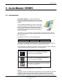
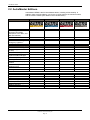
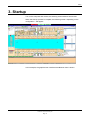
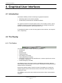
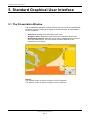
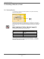
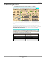
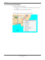
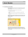
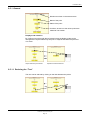
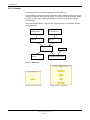
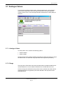
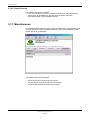
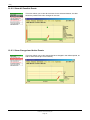
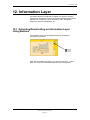
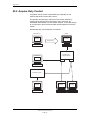
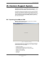
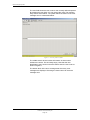
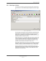
1
Operator's Handbook AutroMaster ISEMS Integrated Safety and Emergency Management System 116-P-AMASTER-OPERATE/FGB, Rev. A, 2011-11-25 COPYRIGHT © This publication, or parts thereof, may not be reproduced in any form, by any method, for any purpose. Autronica Fire and Security AS and its subsidaries assume no responsibility for any errors that may appear in the publication, or for damages arising from the information in it. No information in this publication should be regarded as a warranty made by Autronica Fire and Security AS. The information in this publication may be updated without notice. Product names mentioned in this publication may be trademarks. They are used only for identification. Table of Contents Table of Contents 1. Introduction ...................................................................... 10 1.1 1.2 1.3 About this handbook .......................................................................... 10 The reader ......................................................................................... 10 Reference Documentation ................................................................. 10 2. AutroMaster ISEMS .......................................................... 11 2.1 2.2 Introduction ........................................................................................ 11 AutroMaster Editions ......................................................................... 12 3. Startup .............................................................................. 13 4. Graphical User Interfaces................................................ 14 4.1 4.2 4.3 4.4 Introduction ........................................................................................ 14 The Display ........................................................................................ 14 4.2.1 The Taskbar ............................................................................ 14 4.2.2 Menus at the Top of the Screen .............................................. 16 System Operating Techniques .......................................................... 19 4.3.1 The Graphical System ............................................................. 19 4.3.2 Moving a Window .................................................................... 20 4.3.3 Minimizing and Closing Windows ........................................... 20 4.3.4 Resizing Windows ................................................................... 20 Overview – Loop Units/Point Menus ................................................. 21 4.4.1 Overview – Description of Point Menus .................................. 22 4.4.2 Overview – Emergency Lighting ............................................. 22 4.4.3 Overview – Description of Emergency Lighting Menu Items .. 23 5. Standard Graphical User Interface ................................. 24 5.1 5.2 5.3 5.4 The Presentation Window ................................................................. 24 Navigation Technique ........................................................................ 25 Changing Between Mimics ................................................................ 26 5.3.1 Select Areas ............................................................................ 27 Selecting a Detector or Point ............................................................. 28 5.4.1 Selecting Detectors ................................................................. 28 5.4.2 More Text for a Point ............................................................... 29 5.4.3 Point Menu .............................................................................. 30 6. AutroBrowser ................................................................... 31 6.1 6.2 6.3 6.4 6.5 6.6 Introduction ........................................................................................ 31 The Presentation Window ................................................................. 32 Detail Pane ........................................................................................ 34 Static Navigation Pane ...................................................................... 34 Dynamic Navigation Pane ................................................................. 35 Mimic Control Pane ........................................................................... 35 Operator's Handbook, AutroMaster ISEMS 116-P-AMASTER-OPERATE/FGB, Rev. A, 2011-11-25, Autronica Fire and Security AS Page 3 6.7 6.8 6.9 6.10 6.11 6.12 6.13 6.14 6.15 6.16 6.17 6.18 6.19 Layer Control Pane............................................................................ 36 More Text Pane ................................................................................. 36 Pane Control Pane ............................................................................ 36 Status Bar (configurable) ................................................................... 37 EPT Actors/Objects Pane .................................................................. 38 Default Utility Buttons ........................................................................ 39 Configurable Buttons ......................................................................... 40 6.13.1 Shortkeys – Overview ............................................................ 41 Quick Mouse Operation ..................................................................... 41 6.14.1 Display a Mimic ....................................................................... 41 6.14.2 Scroll inside the Navigation Pane ........................................... 41 6.14.3 Scroll inside the Detail Pane ................................................... 42 6.14.4 Zoom In/Out the Detail Pane ................................................... 42 6.14.5 Brightness Adjustment ............................................................ 42 Customizing the Layout ..................................................................... 43 6.15.1 Rearrange Panes .................................................................... 43 6.15.2 Resize Panes .......................................................................... 44 6.15.3 Hide or Make Panes Visible .................................................... 44 6.15.4 Save layout .............................................................................. 44 Operating Techniques – Using Touchscreen Functionality .............. 45 6.16.1 Default Utility Buttons .............................................................. 45 6.16.2 Mouse Mode Normal (navigation/select) ................................ 45 6.16.3 Mouse Mode Multiselect ......................................................... 45 6.16.4 Mouse Mode Pan .................................................................... 45 6.16.5 Mouse Mode Zoom ................................................................. 46 6.16.6 Mouse Mode Brightness (Day/Night mode) ............................ 46 Selecting Mimics ................................................................................ 46 Selecting Detectors ........................................................................... 49 Accessing Point Menus ..................................................................... 50 7. Alarm Situation................................................................. 51 7.1 7.2 In the Event of an Alarm .................................................................... 51 In the Event of Several Alarms .......................................................... 53 8. AutroMaster Menu............................................................ 54 8.1 8.2 8.3 8.4 8.5 8.6 8.7 AutroMaster > Reset screen.............................................................. 55 AutroMaster > Object list ................................................................... 56 8.2.1 Functions in the Object List ..................................................... 56 AutroMaster > Network topology BS-100 .......................................... 57 8.3.1 Functions in Network topology ................................................ 57 8.3.2 Functions in the Information Window for Control Panels ........ 59 AutroMaster > Detector group manager............................................ 64 8.4.1 Creating Groups ...................................................................... 64 8.4.2 Adding Detectors from the Graphic Display ............................ 65 8.4.3 Adding Detectors from the Object list ..................................... 66 8.4.4 Deleting Groups ...................................................................... 67 8.4.5 Disabling a Group.................................................................... 68 8.4.6 Enabling a Group .................................................................... 69 8.4.7 Time Program for Enabling/Disabling ..................................... 70 AutroMaster > Object browser........................................................... 72 8.5.1 General .................................................................................... 73 8.5.2 Example .................................................................................. 74 AutroMaster > System history ........................................................... 76 AutroMaster > Printouts ..................................................................... 77 8.7.1 AutroMaster > Printouts > Print Screen .................................. 77 8.7.2 AutroMaster > Printouts > Print window .................................. 77 Operator's Handbook, AutroMaster ISEMS 116-P-AMASTER-OPERATE/FGB, Rev. A, 2011-11-25, Autronica Fire and Security AS Page 4 8.8 AutroMaster > Maintenance .............................................................. 78 8.8.1 AutroMaster > Maintenance > Show version .......................... 78 8.8.2 AutroMaster > Maintenance > Select Language .................... 79 8.8.3 AutroMaster > Maintenance > Date/Time ............................... 80 8.8.4 AutroMaster > Maintenance > Backup tools ........................... 80 8.8.5 AutroMaster > Maintenance > Configuration .......................... 83 8.8.6 AutroMaster > Maintenance > Command line ........................ 84 8.9 AutroMaster 5000 > Help .................................................................. 84 8.10 AutroMaster 5000 > Shut Down ........................................................ 84 9. Report Generator ............................................................. 85 9.1 9.2 9.3 9.4 9.5 9.6 Introduction ........................................................................................ 85 Main Page.......................................................................................... 85 Common Functions ........................................................................... 86 List Reports ....................................................................................... 86 Generate Reports .............................................................................. 87 History................................................................................................ 87 9.6.1 History Type ............................................................................ 88 9.6.2 Saving the Report.................................................................... 90 9.7 Analogue Values ............................................................................... 91 9.7.1 Analogue Values ..................................................................... 91 9.7.2 Range ...................................................................................... 91 9.8 Disablements ..................................................................................... 92 9.8.1 Disablements........................................................................... 92 9.8.2 Select Group ........................................................................... 92 9.8.3 Displaying Disablements ......................................................... 93 9.9 Configuration ..................................................................................... 93 9.9.1 Configurations ......................................................................... 93 9.9.2 Select Mimic ............................................................................ 94 9.10 Version Information ........................................................................... 95 9.10.1 Software Version ..................................................................... 95 9.10.2 Select Version ......................................................................... 96 9.11 Miscellaneous .................................................................................... 96 10. History ............................................................................... 97 10.1 Functions in the History Window ....................................................... 98 10.1.1 Scrolling in the History Window............................................... 98 10.1.2 Dating Events .......................................................................... 98 10.1.3 Reading Analogue Values....................................................... 99 10.2 The Vertical Menu ............................................................................. 99 10.2.1 Zoom Vertically........................................................................ 99 10.2.2 Show All Possible Events ........................................................ 100 10.2.3 Show Changed and Active Events .......................................... 100 10.2.4 Show Only Changed Events ................................................... 101 10.2.5 Show Waveforms Only ............................................................ 101 10.2.6 Show Waveforms and Events ................................................. 102 10.2.7 Do Not Show Waveforms ........................................................ 102 10.2.8 Want to See Alarms Only ........................................................ 103 10.2.9 Show Special Events............................................................... 103 10.3 Horizontal........................................................................................... 104 10.4 Miscellaneous .................................................................................... 104 10.4.1 Show Timestamps ................................................................... 104 10.4.2 Sort Events .............................................................................. 105 10.4.3 Quick Refresh.......................................................................... 105 10.4.4 Variable Text Width ................................................................. 106 10.4.5 Waveform Scale: Visible Min/Max........................................... 107 10.4.6 Waveform Scale: Total Min/Max ............................................. 107 Operator's Handbook, AutroMaster ISEMS 116-P-AMASTER-OPERATE/FGB, Rev. A, 2011-11-25, Autronica Fire and Security AS Page 5 10.4.7 Standard Waveform Scale ...................................................... 108 10.4.8 Squared-Off Curves ................................................................ 108 10.5 Other Buttons .................................................................................... 109 10.5.1 The <==> Button ..................................................................... 109 10.5.2 The =><= Button ..................................................................... 110 10.5.3 The |<==>| Button ................................................................... 111 10.5.4 Report Time............................................................................. 111 10.5.5 Adding Detectors to the History Window ................................ 112 11. Disable/Enable Detectors ................................................ 113 11.1 11.2 11.3 11.4 11.5 Working with Several Points .............................................................. 114 Disabled Points .................................................................................. 115 Detector Group Functionality/Overlapping Groups ........................... 115 Replication ......................................................................................... 116 Future Actions ................................................................................... 116 12. Information Layer ............................................................. 117 12.1 Activating/Deactivating an Information Layer Using Buttons ............ 117 12.2 Activating/Deactivating an Information Layer from the Object List ... 118 13. Monitoring Network-Communication: One Master, Multiple Slaves ..................................................................................... 119 14. Operation of Dardo Emergency Lighting ............... 120 14.1 Symbols ............................................................................................. 120 14.2 Commands ........................................................................................ 121 15. Watchdog .......................................................................... 123 16. Time Synchronization ...................................................... 124 17. Fire Doors ......................................................................... 125 18. Low-Location Lighting ..................................................... 126 19. Fire Patrol Supervisor...................................................... 127 20. Closed-circuit Television (CCTV) ................................... 128 21. Video Module .................................................................... 129 22. Programmable Logic Controllers ................................... 131 23. AutroSafe .......................................................................... 132 23.1.1 AutroSafe Detection Zones ..................................................... 132 23.1.2 Selecting AutroSafe Detectors ................................................ 133 Operator's Handbook, AutroMaster ISEMS 116-P-AMASTER-OPERATE/FGB, Rev. A, 2011-11-25, Autronica Fire and Security AS Page 6 23.1.3 Alarm Mimic from AutroSafe ................................................... 133 23.2 AutroSafe History Functions .............................................................. 134 24. AutroSafe Dual Safety with AutroMaster as a Top-level System .................................................................................... 136 24.1 24.2 24.3 24.4 24.5 24.6 AutroSafe Dual Safety Concept ........................................................ 136 Primary and Secondary System ........................................................ 136 Active and Standby Mode.................................................................. 136 Indications.......................................................................................... 137 Automatic Transfer of Loop Control .................................................. 137 Give or Take Loop Control ................................................................ 138 25. Duty Control ..................................................................... 139 25.1 Transfer Duty Control ........................................................................ 139 25.2 Acquire Duty Control ......................................................................... 140 26. Decision Support System ................................................ 141 26.1 Operating AutroMaster DSS .............................................................. 141 26.1.1 Selecting an Incident ............................................................... 143 26.1.2 General Layout of the Incident Viewer .................................... 144 26.1.3 Log Entry View ........................................................................ 146 26.1.4 Data Field View ....................................................................... 146 26.1.5 Incident Close View ................................................................. 147 26.1.6 Operator Action Data Entry ..................................................... 148 27. Electronic Plotting Table ................................................. 150 27.1 Introduction ........................................................................................ 150 27.2 Actors and Objects ............................................................................ 151 27.2.1 Introduction.............................................................................. 151 27.2.2 Symbols Displayed in the EPT Actors and Objects Pane ....... 151 27.2.3 Symbols Displayed in the Detail Pane .................................... 152 27.2.4 Actors ...................................................................................... 153 27.2.5 Objects .................................................................................... 153 27.2.6 Symbol Information ................................................................. 154 27.2.7 Symbol State Indication........................................................... 154 27.3 Accessing Symbol Menus ................................................................. 155 27.3.1 Inside the EPT Actors and Objects Pane ................................ 155 27.3.2 Inside the Detail Pane ............................................................. 155 27.4 Drag and Drop ................................................................................... 156 27.5 Cleaning Symbols .............................................................................. 156 27.6 On Scene Commander Symbol ......................................................... 157 27.6.1 Overview ................................................................................. 157 27.6.2 Menu Selections ...................................................................... 157 27.7 Mobile Fire Group Symbol ................................................................. 158 27.7.1 Overview ................................................................................. 158 27.7.2 Menu Selections ...................................................................... 158 27.8 Stretcher Team Symbol ..................................................................... 159 27.8.1 Overview ................................................................................. 159 27.8.2 Menu Selections ...................................................................... 159 27.9 Supply Team Symbol ........................................................................ 160 27.9.1 Overview ................................................................................. 160 27.9.2 Menu Selections ...................................................................... 160 27.10 Staging Area Symbol ......................................................................... 161 27.10.1 Overview ............................................................................... 161 Operator's Handbook, AutroMaster ISEMS 116-P-AMASTER-OPERATE/FGB, Rev. A, 2011-11-25, Autronica Fire and Security AS Page 7 27.10.2 Menu Selections ................................................................... 161 27.11 Source Location Symbol.................................................................... 162 27.11.1 Overview ............................................................................... 162 27.11.2 Menu Selections ................................................................... 162 27.12 Boundary Cooling Symbol ................................................................. 163 27.12.1 Overview ............................................................................... 163 27.12.2 Menu Selections ................................................................... 163 27.13 Casualty Symbol ................................................................................ 164 27.13.1 Menu Selections ................................................................... 164 27.14 History Window .................................................................................. 165 28. Event Recording and Replay .......................................... 166 28.1 28.2 28.3 28.4 Introduction ........................................................................................ 166 Automatic Start of Recordings ........................................................... 166 Manual Start and Stop of Recordings ............................................... 166 General Layout .................................................................................. 167 28.4.1 Toggling between Full Scale Picture and Zoom ..................... 167 28.4.2 Sequence Window .................................................................. 168 28.4.3 Information in Bottom Window ................................................ 168 28.4.4 Function Buttons ..................................................................... 169 28.4.5 Play Button .............................................................................. 169 28.4.6 Export Button ........................................................................... 171 28.4.7 Delete Button........................................................................... 172 29. Training/Simulate Module ............................................... 173 29.1 29.2 29.3 29.4 29.5 29.6 Introduction ........................................................................................ 173 The Training/Simulate Window ......................................................... 174 Function Buttons ................................................................................ 174 Starting the Training Module ............................................................. 175 Starting and Stopping a Scenario ...................................................... 175 Starting an Event from the Detail Pane ............................................. 176 30. Message Center................................................................ 177 30.1 Introduction ........................................................................................ 177 30.2 Using the Message Center ................................................................ 177 31. Reader’s Comments ........................................................ 183 Operator's Handbook, AutroMaster ISEMS 116-P-AMASTER-OPERATE/FGB, Rev. A, 2011-11-25, Autronica Fire and Security AS Page 8 Operator's Handbook, AutroMaster ISEMS 116-P-AMASTER-OPERATE/FGB, Rev. A, 2011-11-25, Autronica Fire and Security AS Page 9 Introduction 1. Introduction 1.1 About this handbook This handbook provides information to successfully operate the AutroMaster Integrated Safety and Emergency Management System (AutroMaster ISEMS). 1.2 The reader The handbook is intended for personnel who operate the AutroMaster Integrated Safety and Emergency Management System. 1.3 Reference Documentation The AutroMaster ISEMS documentation consists of the following documents: Document Name Part number File name System Description 116-AMASTER-SYSTEM/XGB amastersystem_xgb Basic Configuration Handbook 116-AMASTER-BASICCONF/EGB amasterbasicconf_egb Advanced Configuration Handbook 116-AMASTER-ADVCONF/EGB amasteradvconf_egb Installation and Commissioning Handbook Operator’s Handbook 116-AMASTER-INSTCOMM/IGB amasterinstcomm_igb 116-AMASTER-OPERATE/FGB amasteroperate_fgb Shortform User Guide 116-AMASTER-USERGUI/LGB amasterusergui_lgb Datasheet: AutroMaster ISEMS 116-AMASTER-ISEMS/CGB amasterisems_cgb Operator's Handbook, AutroMaster ISEMS 116-P-AMASTER-OPERATE/FGB, Rev. A, 2011-11-25, Autronica Fire and Security AS Page 10 AutroMaster ISEMS 2. AutroMaster ISEMS 2.1 Introduction AutroMaster ISEMS is an Integrated Safety and Emergency Management System which can be used together with the AutroSafe Interactive Fire Detection System. The AutroMaster ISEMS has an intuitive control and monitoring interface, providing an easy-to-understand graphical presentation of the premises and events that may occur. Navigation is fast and instinctual, and the powerful zoom functions allow you to monitor all areas in great detail. The system can be connected to a large number of fire-alarm panels of different types (such as operator, control or repeater panels) via a serial connection or an ethernet network. AutroMaster uses Linux1 as an operating system. Computer platform PC Operating system Cent0S 5.6 Comments AutroMaster functionality varies depending on which platform/ operating system it is running on, and whether it is connected to AutroSafe or Saia PLC. In this handbook, the following symbols are used to indicate information relating to a specific operating systems and/or types of fire-alarm panel: Symbol Comments The function is only available for AutroSafe panels connected to AutroMaster. The function is only available for Autroprime panels connected to AutroMaster. The function is only available for BS-100 panels connected to AutroMaster. Registered trademarks. 1) Linux is a registered trademark of Linus Torvalds. Figures The figures used in this handbook are diagrammatic and are intended to reflect the appearance that the user can expect, thus the content of the windows will be roughly the same for all platforms. Variation in appearance may occur due to customer-specific configuration, differences between platforms/operating systems. Operator's Handbook, AutroMaster ISEMS 116-P-AMASTER-OPERATE/FGB, Rev. A, 2011-11-25, Autronica Fire and Security AS Page 11 AutroMaster ISEMS 2.2 AutroMaster Editions AutroMaster ISEMS is the full AutroMaster edition, including all functionality. In addition, there are three editions; one for the oil & gas market, the maritime market, and the onshore market (see details in the overview below). Functions/Modules Basic functionality Fire management basic functions (AutroSafe, Autroprime 2.0 or later, and BS-100 interface) MultiSensor control Report generator Control and monitoring of emergency lights/LLL Extended functionality AutroSafe IFG unit support Dual Safety (AutroSafe 4.3 or later) Touch screen support Decision support system/incident manager Electronic plotting table Training/simulation module Event record and replay module Video module (live video support CCTV) Remote connect function Message center module Interfaces Hernis CCTV interface System-S interface NMEA interface Saia PLC support VDR output Siemens S7 PLC support Modbus interface ESPA 4.4.4 interface Oil & Gas Maritime Onshore ISEMS x x x x x x x x x x x x x x x x x x NA x NA x x x x x x x x x x x x x x x x x x x x x x Operator's Handbook, AutroMaster ISEMS 116-P-AMASTER-OPERATE/FGB, Rev. A, 2011-11-25, Autronica Fire and Security AS Page 12 x x x x x x x x Startup 3. Startup Turn on the computer and monitor; the start-up process takes a few minutes. When the start-up process is complete, the following screen- depending on the configuration – will appear: In this example, the graphical user interface AutroBrowser view is shown. Operator's Handbook, AutroMaster ISEMS 116-P-AMASTER-OPERATE/FGB, Rev. A, 2011-11-25, Autronica Fire and Security AS Page 13 Graphical User Interfaces 4. Graphical User Interfaces 4.1 Introduction AutroMaster ISEMS provides the following two graphical interfaces: Standard graphical user interface (default) AutroBrowser (introduced with AutroMaster ISEMS) The graphical interfaces comprise display views, menu handling, buttons, panes, navigation techniques, system operating techniques, the change of mimics, the selection of points (detectors, manual call points, etc.). For detailed information on each of these graphical user interfaces, see chapter 5 and 6, respectively. 4.2 The Display 4.2.1 The Taskbar The taskbar, by default, contains the following elements: AutroMaster Console Disable/Enable Faults and Alarms Event Replay (if included) Training/Simulate (if included) Presentation window (normally identified with a customer-specific title such as, for example, “Autronica”). Incident Manager (if included) AutroMaster (menu) gives users access to AutroMaster functionality, while the other elements refer to windows on the screen; AutroMaster maximizes/minimizes default windows automatically. Note that the default windows cannot be closed. The taskbar may contain nondefault programs and windows that have been minimized, these may safely be closed by the user. AutroMaster: clicking this button reveals several options, these are described in chapter 8 Operator's Handbook, AutroMaster ISEMS 116-P-AMASTER-OPERATE/FGB, Rev. A, 2011-11-25, Autronica Fire and Security AS Page 14 Graphical User Interfaces Console: opens a window for system messages (normally runs in the background – does not require user interaction) Disable/Enable: opens a window for overview and control of disablements and detector groups (normally maximized). Faults and Alarms: opens a window for system faults (normally maximized), containing fault reports for system faults from AutroSafe or BS-100 fire-alarm systems, plus active alarms. The information is presented in the following format: <Date/Time><Unit name><Fault Class/Type > A fault can be acknowledge by right-clicking the mouse inside the window and selecting Acknowledge. Presentation Window: the window which contains the customer-specific data and site mimic (normally maximized). To return all windows to their original states and minimize non-default windows, select AutroMaster 5000 > Reset screen. Operator's Handbook, AutroMaster ISEMS 116-P-AMASTER-OPERATE/FGB, Rev. A, 2011-11-25, Autronica Fire and Security AS Page 15 Graphical User Interfaces 4.2.2 Menus at the Top of the Screen The menus at the top of the screen allow control of access level, response to alarms and – if configured – Duty Control and Day/Night Control. 4.2.2.1 Day/Night Control – Display Dimming (if configured) Day/night control provides damping for light emission from the AutroMaster display. The menu contains settings for “Day” and “Night”; “Day” sets the display to full brightness, “Night” sets the display to minimal light emission. Two further options “Brighter” and “Darker” allow for adjustment between and outside these two settings. 4.2.2.2 Duty Control (if configured) When two AutroMasters are connected together, duty control may be transferred from one machine to another. It is the operator with duty control who acknowledges/resets alarms. Note: Duty control may only be transferred if the system comprises two machines connected together in a network and when duty control transfer is defined on both. On AutroMaster 5000s where no duty control is configured, this menu will not appear. Operator's Handbook, AutroMaster ISEMS 116-P-AMASTER-OPERATE/FGB, Rev. A, 2011-11-25, Autronica Fire and Security AS Page 16 Graphical User Interfaces 4.2.2.3 Security-Clearance Level/User Mode This menu changes to indicate the current security-clearance level of the operator. Level 1 2 Name Observe Operate 3 Configure 4 Service Comment Observation only. Permission to disable/reset control panels and/or disable/enable detectors. Permission to configure text messages, detectors, etc. Access to command-line functions. To change security-clearance level: click and hold the menu label, and select a new security-clearance level. A password is required to access higher security-clearance levels; enter passwords using either keyboard or mouse. No password required to change to lower security-clearance levels. When changing to higher security-clearance levels, the password dialogue appears prompting the user to enter a password; do this by clicking the keyboard in the dialogue (using the left mouse button) or by using the keyboard. Click OK or press <RETURN> to confirm. Incorrect passwords result in an error message, entering a correct password gives access to the new security-clearance level. 4.2.2.4 Reset The reset menu allows points to be reset; to do this, click a point to select it and choose Reset > Yes. Selecting a point with the mouse and right-clicking with both the mouse reveals a menu. Points can also be reset from this menu by choosing Reset. 4.2.2.5 Acknowledge When a point in alarm is selected, this menu allows the following functions: Operator's Handbook, AutroMaster ISEMS 116-P-AMASTER-OPERATE/FGB, Rev. A, 2011-11-25, Autronica Fire and Security AS Page 17 Graphical User Interfaces Acknowledge > Silence fire – all sounders are silenced. Acknowledge > Acknowledge all – all alarms and faults are acknowledged Acknowledge > Local mute – the PC buzzer is silenced. 4.2.2.6 AutroMaster Screensaver In periods of inactivity, the AutroMaster screensaver (a moving Autronica product logo) is activated. The screensaver disappears as soon as the system mouse is moved. Operator's Handbook, AutroMaster ISEMS 116-P-AMASTER-OPERATE/FGB, Rev. A, 2011-11-25, Autronica Fire and Security AS Page 18 Graphical User Interfaces 4.3 System Operating Techniques Note: All the processes described below presuppose use of the left mouse button, unless stated otherwise. 4.3.1 The Graphical System All windows have the same basic format, with title bar and icons in the corners. Operator's Handbook, AutroMaster ISEMS 116-P-AMASTER-OPERATE/FGB, Rev. A, 2011-11-25, Autronica Fire and Security AS Page 19 Graphical User Interfaces 4.3.2 Moving a Window To move a window, move the cursor to the title bar, click and hold down the left mouse button and then drag the window to the desired position, then release the mouse button. 4.3.3 Minimizing and Closing Windows This button is used to minimize windows. This button is used to close windows/applications. Note: Not all windows can be closed. 4.3.4 Resizing Windows Windows can be resized by clicking, holding and dragging the window frame. When the cursor is moved to the correct position on the window frame, it changes to a double-headed arrow. Operator's Handbook, AutroMaster ISEMS 116-P-AMASTER-OPERATE/FGB, Rev. A, 2011-11-25, Autronica Fire and Security AS Page 20 Graphical User Interfaces 4.4 Overview – Loop Units/Point Menus x x x BC-320˚ x x x Modules* x x x x Manual call-points x x x x x x x x Optical detectors x x x x x x x x Heat detectors x x x MultiSensor x x x x x x x AutroBeam x x x x AutroFlame x x x AutroSense x x x Conventional loop interfaces x x Ionisation detector x x Misc. units‡ x x BN-300 x x x BN-320 (e.g. fire-door control) x x x BN-320/3 (e.g. LLL) x x x x x x BN-320/4 (e.g. std. control unit) x x x x x x BN-320/5 x x x x x x x Gas detectors, PowerLoop x x x x x x x Detection zone x x x x x x x x x x BN-300/DZ x x x x x x x x x x Manual call-point/DZ x x x x x x x x x x x Optical detector/DZ x x x x x x x x x x x Heat detector/DZ x x x MultiSensor/DZ x x x AutroBeam/DZ x x AutroFlame/DZ x x AutroSense/DZ x Gas detectors, PowerLoop Conventional loop interface/DZ hj BS-100 detectorª Open (config. option) BS-320˚ Close (config. option) x Turn ON x Turn OFF x x Test mode on/off Silence single system x x Start/stop trending Gas Det. Re-sound single sys. x Outputs Alarm zones Temperature Reset single system x Prolong delay x History Disable/enable x Alarm units† Disable/enable Smoke Det. Configuration Turn ON LED (Autroprime only) Point Menus Accept faults Loop Units x x x x x x x x x x x x x x x x x x x x x x x x x x x x x x x x x x x x x x x x x x x x x x x x Combined Point and DZ x x x x x x x x x x x x x x x x x x x x x x x x x x x x x x x x x x x x x x x x x x x x x x x x x x x x x x x x x x x x Ionisation detector/DZ x x x x x x x x x x BN-320/5/DZ x x x x x x x x x x x x Operator's Handbook, AutroMaster ISEMS 116-P-AMASTER-OPERATE/FGB, Rev. A, 2011-11-25, Autronica Fire and Security AS Page 21 Graphical User Interfaces Notes: † Including: BBR-110, BBR-120, Bells, Loop Sounders, Alarm Zone ˚ AutroSafe only * Including BSB-310/01, BSD-310/01, BSD-310/02, BSD-310/03, BSD-310/04, BSD-310/05, BSE-310 ‡ Including: BU-200, BW-200, BW-2020, BW-203, GAPB ª Including BS-100 detectors connected to AutroSafe via BSD-330. 4.4.1 Overview – Description of Point Menus Point Menus Description Accept faults Accept fault from units that report faults, marks fault as accepted in Alarms and Faults window Configuration Used in conjunction with History, Detector-group manager , Object list Disable/Enable Disable/Enable the point, adds the point to/removes the point from disablements list History Open the System history window for the selected point Prolong delay Prolong the delay between alarm levels Reset single system Reset the fire-alarm panel associated with the point Re-sound single system Re-sound the fire-alarm panel associated with the point Silence single system Silence the fire-alarm panel associated with the point Temperature Updates the point temperature-reading in the Information Pane Test mode off Turn test mode off for the detector zone or combined point/ detector zone Test mode on Turn test mode on for the detector zone or combined point/ detector zone Turn off Activate the output Turn on De-activate the output Close Activate the output (e.g. fire doors) Open De-activate the output (e.g. fire doors) Disable smoke detection Disable smoke detection for a selected MultiSensor Enable smoke detection Enable smoke detection for a selected MultiSensor Start/stop trending of gas detectors Gas detectors connected to PowerLoop 4.4.2 Overview – Emergency Lighting x DardoPlus panel x x x x Configuration x History x Enable Test Disable Line 1 x Disable Test Battery test (odd addr.) Dardo2 panel Disable Line 2 Battery test (even addr.) Point Menus Function test Units x x x x x x x x x OvaLight2 x x OvaLightPlus x x OvaLine2 x x OvalinePlus x x Operator's Handbook, AutroMaster ISEMS 116-P-AMASTER-OPERATE/FGB, Rev. A, 2011-11-25, Autronica Fire and Security AS Page 22 Graphical User Interfaces 4.4.3 Overview – Description of Emergency Lighting Menu Items Point Menu Function test Battery test (even addr.) Battery test (odd addr.) Disable Line 1 Disable Line 2 Disable Test Enable Test History Configuration Description Tests the functionality of the system Starts battery-discharge test of armatures with even addresses Starts battery-discharge test of armatures with odd addresses Disables emergency power to Line 1 Disables emergency power to Line 2 Disables automatic tests Enables automatic tests Open the System history window for the selected point Used in conjunction with History, Detector-group manager, Object list Operator's Handbook, AutroMaster ISEMS 116-P-AMASTER-OPERATE/FGB, Rev. A, 2011-11-25, Autronica Fire and Security AS Page 23 Standard Graphical User Interface 5. Standard Graphical User Interface 5.1 The Presentation Window The AutroMaster presentation window provides the mimic function of AutroMaster; the mimic function is the graphical display of the alarmed area. The presentation window comprises: Detail Pane: displays the focused area of the mimic Navigation Pane: displays the entire mimic area, indicating current focus Miscellaneous Buttons: allow the user to switch to different mimics, and turn on/off information layers. The total number of buttons depends on the complexity of your system. Buttons The "Block B" button is used to change to a mimic of Block B. The "Block C" button is used to change to a mimic of Block C. Operator's Handbook, AutroMaster ISEMS 116-P-AMASTER-OPERATE/FGB, Rev. A, 2011-11-25, Autronica Fire and Security AS Page 24 Standard Graphical User Interface 5.2 Navigation Technique There are three ways to navigate in AutroMaster. A. Position the cursor in the Navigation Pane and left-click outside the frame that represents the focused area displayed in the Detail Pane. B. Position the cursor in the Detail Pane and hold down the middle mouse button while moving the mouse. C. Position the cursor within the frame of the Navigation Pane and hold down the left mouse button while moving the mouse. Operator's Handbook, AutroMaster ISEMS 116-P-AMASTER-OPERATE/FGB, Rev. A, 2011-11-25, Autronica Fire and Security AS Page 25 Standard Graphical User Interface 5.3 Changing Between Mimics The system can contain many different mimics. In this example, the system contains 3 mimics. Overview This picture provides an overview of the entire alarmed area. Block B Alarm mimic for block B. This display contains all the floors and detectors in block B. Block C Alarm mimic for block C. This display contains all the floors and detectors in block C. The system can also include other mimics, especially land-based systems. To change mimics, left-click one of the buttons on the right hand side of the pictures. Overview A Block B Block C Operator's Handbook, AutroMaster ISEMS 116-P-AMASTER-OPERATE/FGB, Rev. A, 2011-11-25, Autronica Fire and Security AS Page 26 Standard Graphical User Interface 5.3.1 Select Areas Selected areas or short-cuts may be defined in the picture. A short-cut is a technique for changing mimics by clicking on a specific area (which has been defined as a short-cut) in the mimic. Left-click a specific area in the mimic. Change to a specific building. Note: A short-cut will only function when it has been defined. Operator's Handbook, AutroMaster ISEMS 116-P-AMASTER-OPERATE/FGB, Rev. A, 2011-11-25, Autronica Fire and Security AS Page 27 Standard Graphical User Interface 5.4 Selecting a Detector or Point 5.4.1 Selecting Detectors To read data from a detector, left-click the detector. The system automatically selects the nearest detector. Additional information about the selected detector is presented in an Information Pane above the Detail Pane (the selected detector is indicated by a line linking it to the Information Pane). The Information Pane displays information in the following format: This information should be read in the following way: Text 8:03:03 Description Date the detector status was last changed. A0001 Detector number. Block B. 5Th Floor, Office 501 Customer text (from BS-100) Normal Detector/Point status. 72* Analogue value (22C) Temperature The Information Pane may be followed by a button labelled More…, clicking this button makes the information dialogue appear with any programmed additional information, see section 5.4.2 below. Operator's Handbook, AutroMaster ISEMS 116-P-AMASTER-OPERATE/FGB, Rev. A, 2011-11-25, Autronica Fire and Security AS Page 28 Standard Graphical User Interface 5.4.2 More Text for a Point Detectors may have additional text attached. To view more text left-click More… to the right of the detector text. Left-click More… again to deactivate the text. Additional text can be defined for the various statuses of a detector. Additional text for detectors in alarm, pre-warning, error and normal status are shown here. Text for normal status. Text for alarm. Text for pre-warning Text for fault status. Operator's Handbook, AutroMaster ISEMS 116-P-AMASTER-OPERATE/FGB, Rev. A, 2011-11-25, Autronica Fire and Security AS Page 29 Standard Graphical User Interface 5.4.3 Point Menu All configured points have a point menu. There are two ways of accessing a point’s menu; Right-click the point in question or Left-click the point in question (if not already selected), then left-click the Menu button at the top of the presentation window. Note: point menus are user configurable; see project-specific documentation for further details. See section 4.4 for details of the possible menu options and their function. 5.4.3.1 Detectors, AutroSafe and BS-100 See section 4.4 for an overview of possible menu options. Operator's Handbook, AutroMaster ISEMS 116-P-AMASTER-OPERATE/FGB, Rev. A, 2011-11-25, Autronica Fire and Security AS Page 30 AutroBrowser 6. AutroBrowser 6.1 Introduction The AutroBrowser provides a user-friendly graphical interface, including various useful functions. Zoom; simple zoom functionality Movable/floating panes (move, rearrange and dock panes) High resolution graphics; suitable for widescreen/higher resolution and dual screen setups Drag and drop of Electronic Plotting Table (EPT) actors Multiselect of objects; define groups, disable/enable, trending, etc. Live video support; inputs to analogue CCTV (see chapter 21) Picture control Layer control Operator's Handbook, AutroMaster ISEMS 116-P-AMASTER-OPERATE/FGB, Rev. A, 2011-11-25, Autronica Fire and Security AS Page 31 AutroBrowser 6.2 The Presentation Window The AutroMaster presentation window provides a graphical display of the site, including various panes, buttons and elements for display control and navigation. The presentation window includes (see illustration on next page): Detail Pane: Displays the focused area (the area chosen in the Static or Dynamic Navigation Pane). Static Navigation Pane: The Static Navigation Panel displays the entire mimic area. A small movable navigation box inside the pane is used to choose a focused area in the Detail Pane. There can be one or several of these panes. Dynamic Navigation Pane: Displays the mimic that is selected in the Mimic control Pane. Mimics displayed are not configured as static navigation panes. More Text Pane: Displays additional information (if configured) for the selected tag. Status Bar (configurable): Tags can be displayed in the status bar, providing information on status and analogue values (for example, temperature 20oC) Default Utility Buttons: Navigation, Multiselect, Zoom, Day/Night mode Configurable Buttons: For example, to turn on/off information layers, to give easy access to important tags in the system, etc. The total number of buttons depends on the complexity of the system. Mimic Control Pane: Pane showing all available mimics (both static and dynamic mimics). Layer Control Pane: Pane showing all available layers (configurable). Checkboxes allows you to hide a layer or make a layer visible. Electronic Plotting Table Actors: Displays all preconfigured actors. Each actor has its own symbol. Information Pane Information for a selected point is shown in an Information Pane in the uppermost left hand corner of the Detail Pane (see example below). The different panes, buttons and other elements are described in separate chapters. Operator's Handbook, AutroMaster ISEMS 116-P-AMASTER-OPERATE/FGB, Rev. A, 2011-11-25, Autronica Fire and Security AS Page 32 AutroBrowser Default Utility buttons Configurable Buttons (layer control) Dropdown Buttons (tags) Layer Control Pane Mimic Control Pane Static Navigation Pane Electronic Plotting Table Actors/Objects Pane Detail Pane Dynamic Navigation Pane Mimic Name Status Bar Information Operator's Handbook, AutroMaster ISEMS 116-P-AMASTER-OPERATE/FGB, Rev. A, 2011-11-25, Autronica Fire and Security AS Page 33 AutroBrowser 6.3 Detail Pane The Detail Pane is the focused area, i.e. the area chosen in the Static Navigation Pane. It contains the customer-specific data and site mimic (normally maximized) and will always appear on the screen. 6.4 Static Navigation Pane The Static Navigation Panel displays the entire mimic area and is always visible. A small movable navigation box inside the pane is used to choose a focused area in the Detail Pane. There can be one or several of these panes (configurable). Operator's Handbook, AutroMaster ISEMS 116-P-AMASTER-OPERATE/FGB, Rev. A, 2011-11-25, Autronica Fire and Security AS Page 34 AutroBrowser 6.5 Dynamic Navigation Pane The Dynamic Navigation Pane displays the last selected mimic (selected in the Mimic Control Pane). When clicking inside the Dynamic Navigation Pane, the last selected mimic will be shown in full size. Note that the Detail Pane (a selection in the Mimic Control Pane) will never appear in this pane. 6.6 Mimic Control Pane The Mimic Control Pane (browser) shows all available mimics (both static and dynamic mimics). To select a mimic, position the cursor inside the pane, and left-click the box for the mimic in question. (In this example, the mimic “Legend” is selected). The colour of a mimic box will change to a different colour if a fault, a prewarning or an alarm situation occurs; fault: yellow prewarning: orange alarm: red The box will also flash (accompanied by a audio signal) if a prewarning or an alarm situation occurs. Operator's Handbook, AutroMaster ISEMS 116-P-AMASTER-OPERATE/FGB, Rev. A, 2011-11-25, Autronica Fire and Security AS Page 35 AutroBrowser 6.7 Layer Control Pane The Layer Control Pane shows the available layers (configurable). Each layer is also represented by a button (see Configurable Buttons). To make a layer visible or hide a layer, left-click inside the layer’s checkbox. A mark inside a layer’s checkbox indicates that a layer is visible in the Detail Pane and the Navigation Pane. In the example below, the layers “Fire” and “Door” are visible. 6.8 More Text Pane During configuration, additional text can be added to a tag, and each status of a tag can be given a unique text. The More Text Pane displays additional information for a selected tag (if configured). The example below shows the More Text Pane for the tag “Hazardous Material”. 6.9 Pane Control Pane The Pane Control Pane includes a checkbox list for all available panes in the configuration. Panes that are ticked off in the checkbox will be visible. Operator's Handbook, AutroMaster ISEMS 116-P-AMASTER-OPERATE/FGB, Rev. A, 2011-11-25, Autronica Fire and Security AS Page 36 AutroBrowser 6.10 Status Bar (configurable) Tags can be displayed in the status bar, providing information on status and analogue values (for example, temperature 20oC). Operator's Handbook, AutroMaster ISEMS 116-P-AMASTER-OPERATE/FGB, Rev. A, 2011-11-25, Autronica Fire and Security AS Page 37 AutroBrowser 6.11 EPT Actors/Objects Pane The EPT Actors/Objects Pane displays all preconfigured actors and objects used for the Electronic Plotting Table. Each actor/object has its own symbol. For detailed information, refer to chapter 27.2. Operator's Handbook, AutroMaster ISEMS 116-P-AMASTER-OPERATE/FGB, Rev. A, 2011-11-25, Autronica Fire and Security AS Page 38 AutroBrowser 6.12 Default Utility Buttons The overview below shows the default utility buttons. Network Received Indicator (red/yellow/green) The colour indicates the quality of what is shown on screen / transmission speed Menu Turns on /off the menu of a selected tag when a tag is selected. Zoom reset Shortkey Esc Mouse Mode Normal (navigation/select) Shortkey N Zoom Out Shortkey F2 Mouse Mode Multiselect Shortkey M Operate the mouse: Left-click and hold down the mouse button, then move the mouse in any direction to select objects in an area inside a frame Zoom In Shortkey F1 Mouse Mode Brightness (Day/Night mode) Shortkey B Operate the mouse: Left-click and hold down the mouse button, then move up/down or use the mouse Mouse Mode Pan Shortkey P Operate the mouse: Left-click and hold down the mouse button, then move in any direction or use the mouse wheel Mouse Mode Zoom Shortkey Z Operate the mouse: Left-click and hold down the mouse button, then move Operator's Handbook, AutroMaster ISEMS 116-P-AMASTER-OPERATE/FGB, Rev. A, 2011-11-25, Autronica Fire and Security AS Page 39 AutroBrowser 6.13 Configurable Buttons In addition to the Default Utility Buttons, several Configurable Buttons can be added, for example, buttons used to turn on/off information layers (hide or make visible), buttons giving easy access to important tags in the system, etc. The total number of configurable buttons depends on the complexity of your system. The example below shows 9 buttons for layer control and 3 global command buttons with dropdown menus. Layer Control Buttons used to hide a layer or make a layer visible The same layers are listed in the Layer Control Pane (shown below) Global Command Buttons (examples) with dropdown menus. The dropdown menus in this example are shown below. Layer Control . Operator's Handbook, AutroMaster ISEMS 116-P-AMASTER-OPERATE/FGB, Rev. A, 2011-11-25, Autronica Fire and Security AS Page 40 AutroBrowser 6.13.1 Shortkeys – Overview Function Pan mode Zoom mode Horizontal scrolling Multiselect mode Clear multiselect Cancel (returns to Mouse Mode normal) Zoom reset Mouse Mode Zoom Zoom in Zoom out Show the next Mimic in the Mimic Control Pane Show the previous Mimic in the Mimic Control Pane Mouse Mode Normal (navigation/select) Mouse Mode Multiselect Mouse Mode Pan Mouse Mode Brightness (Day/Night mode) Key operation Press and hold Ctrl Press and hold Shift Press and holde Alt Press S Escape Escape Escape z F1 F2 F9 F10 n m p b 6.14 Quick Mouse Operation In addition to shortkeys, quick mouse operation is possible using a combination of buttons, mouse click and mouse wheel. 6.14.1 Display a Mimic Click any mimic in the Mimic Control Pane or click inside a Navigation Pane (if available). 6.14.2 Scroll inside the Navigation Pane Move around inside the Navigation Pane: Position the cursor inside the navigation Pane, click and hold the left mouse button, then move the mouse in any direction. Operator's Handbook, AutroMaster ISEMS 116-P-AMASTER-OPERATE/FGB, Rev. A, 2011-11-25, Autronica Fire and Security AS Page 41 AutroBrowser 6.14.3 Scroll inside the Detail Pane Move the Detail Pane in any direction: Position the cursor inside the Detail Pane, click and hold the left mouse button, then move the mouse in any direction. Scroll the Detail Pane vertically (up and down): Position the cursor inside the Detail Pane, then use the mouse wheel to scroll vertically. Scroll the Detail Pane horizontally: Position the cursor inside the Detail Pane, press Alt and use the mouse wheel to scrool horizontally. Scroll the Detail Pane page by page: Position the cursor inside the Detail Pane, press Ctrl, then use the mouse wheel to scroll vertically page by page. Scroll the Detail Pane page by page: Position the cursor inside the Detail Pane, press Alt + Ctrl, then use the mouse wheel to scroll horizontally page by page. 6.14.4 Zoom In/Out the Detail Pane Zoom in and out Press and hold the Shift button. Use the mouse wheel to zoom in and out. or Click the Mouse Mode Zoom button, click and hold the left mouse button, then move the mouse up or down. 6.14.5 Brightness Adjustment To control the brightness; Click the Mouse Mode Brightness button, then use the mouse wheel to adjust the brightness (up darker, down brighter) or Click the Mouse Mode Brightness button, click and hold the left mouse button, then move the mouse up or down. Operator's Handbook, AutroMaster ISEMS 116-P-AMASTER-OPERATE/FGB, Rev. A, 2011-11-25, Autronica Fire and Security AS Page 42 AutroBrowser 6.15 Customizing the Layout The layout can be customized in respect to: the position of each pane the size of each pane whether a pane is visible or hidden Note that the Detail Pane cannot be moved or resized. When all changes are done, the layout must be saved. 6.15.1 Rearrange Panes The panes can be rearranged, i.e. moved and docked to any position. Position the cursor on the uppermost part of the pane (near the heading of the pane), and hold down the left mouse button while moving the mouse to another position. When the pane is placed in its desired position, release the left mouse button. The pane will snap to the desired position (in the example, the pane will snap to the position in the direction the arrows are pointing. The panes nearby this position will automatically be reduced in size when the pane is moved towards its position. Operator's Handbook, AutroMaster ISEMS 116-P-AMASTER-OPERATE/FGB, Rev. A, 2011-11-25, Autronica Fire and Security AS Page 43 AutroBrowser 6.15.2 Resize Panes The panes can be resized. Position the cursor close up to the pane’s outside frame (a resize symbol will appear), and hold down the left mouse button while moving the mouse up/down to resize vertically left/right to resize horizontally up/down diagonally to resize vertically/horisontally When the pane is resized as desired, release the left mouse button. 6.15.3 Hide or Make Panes Visible The panes can be hidden or they can be made visible. To hide a pane, click the cross in the uppermost right corner of the pane. To make a pane visible, position the cursor on the uppermost part of the pane (near the heading of the pane), then right-click. A checkbox (Pane Control) will appear, showing all available panes. Tick off the panes you want to make visible. 6.15.4 Save layout When all changes are done, the layout must be saved. To save a layout, the Service access level is required. Position the cursor on the Save Layout symbol on the uppermost right hand side of the screen (close to and on the left side of date and time). Click the left mouse button. A dialogue box will appear. Click OK to save the new layout. Operator's Handbook, AutroMaster ISEMS 116-P-AMASTER-OPERATE/FGB, Rev. A, 2011-11-25, Autronica Fire and Security AS Page 44 AutroBrowser 6.16 Operating Techniques – Using Touchscreen Functionality 6.16.1 Default Utility Buttons All default utility buttons are designed for touchscreen. 6.16.2 Mouse Mode Normal (navigation/select) Point at the button. To select an object inside the Detail Pane, point at the object. To scroll, point a certain distance away from an object (the grab symbol will appear), then scroll. 6.16.3 Mouse Mode Multiselect Point at the button. Point anywhere inside the Detail Pane, then hold down the left mouse button and move in any direction to create a frame that includes the objects you want to select. 6.16.4 Mouse Mode Pan Point at the button. Point anywhere inside the Detail Pane, then move in any direction. Operator's Handbook, AutroMaster ISEMS 116-P-AMASTER-OPERATE/FGB, Rev. A, 2011-11-25, Autronica Fire and Security AS Page 45 AutroBrowser 6.16.5 Mouse Mode Zoom Point at the button. Point anywhere inside the Detail Pane, then move up to zoom out or move down to zoom in. 6.16.6 Mouse Mode Brightness (Day/Night mode) Point at the button. Point anywhere inside the Detail Pane, then move up for a brighter view or move down for a darker view. 6.17 Selecting Mimics The system can contain many different mimics. The Mimic Control Pane (refer to chapter 6.6) shows all available mimics (both static and dynamic mimics). All mimics are also shown by right-clicking the top frame of any pane. Short-cuts can be defined for specific areas inside the Detail Pane (normallay configured in land-based installations). When left-clicking such an area, a more detailed mimic of the location will appear automatically. Short-cuts are included in the Mimic Control Pane as well, and can be accessed from this pane. In this example, the system contains 3 mimics. Operator's Handbook, AutroMaster ISEMS 116-P-AMASTER-OPERATE/FGB, Rev. A, 2011-11-25, Autronica Fire and Security AS Page 46 AutroBrowser GA An overview of the entire alarmed area Sideview An overview of the fire door control and indication panel Operator's Handbook, AutroMaster ISEMS 116-P-AMASTER-OPERATE/FGB, Rev. A, 2011-11-25, Autronica Fire and Security AS Page 47 AutroBrowser System The system configuration / structure including all AutroMaster units and fire detection panels. Legend An overview of all symbols used in the system Operator's Handbook, AutroMaster ISEMS 116-P-AMASTER-OPERATE/FGB, Rev. A, 2011-11-25, Autronica Fire and Security AS Page 48 AutroBrowser 6.18 Selecting Detectors To read data from a detector, left-click the detector in question. The system automatically selects the detector that is nearest the position of the cursor. Information for the selected detector is shown in an Information Pane in the uppermost left hand corner of the Detail Pane. The selected detector is indicated by a line linking it to the Information Pane. The Information Pane displays information in the following format: This information should be read in the following way: Text Tuesday 16/3 13:23:25 Description Dateand time the detector status was last changed. A2855 Detector number. DATA RACK DECK11 STB MFZ1 Customer text Normal Detector/Point status. 100 Analogue value (20oC) Temperature Operator's Handbook, AutroMaster ISEMS 116-P-AMASTER-OPERATE/FGB, Rev. A, 2011-11-25, Autronica Fire and Security AS Page 49 AutroBrowser 6.19 Accessing Point Menus All configured points have point menus. To access the menu for a selected point, right-click the point, or use the menu button at the top of the presentation window. The example below shows the menu for a selected detector. Operator's Handbook, AutroMaster ISEMS 116-P-AMASTER-OPERATE/FGB, Rev. A, 2011-11-25, Autronica Fire and Security AS Page 50 Alarm Situation 7. Alarm Situation 7.1 In the Event of an Alarm When an alarm is given, an alarm window will automatically appear accompanied by an audio signal. The system will also show any additional text attached to the detector giving alarm. In the event of alarm, the following procedure should be followed: Investigate the alarm location. Deactivate the alarm sounders on the control panels by clicking the Silence button. When it is safe to reset the control panels, click and hold the Reset menu and choose Yes. Note: This is only a guideline for operating fire-alarm control panels in alarm situations. In most instances, the operator must follow local procedures for dealing with alarms. Alarm display When an alarm is given, the mimic will alter to indicate the alarm location. The Detail Pane will show a flashing detector until you click the "Silence" button. The Information Pane will show the analogue value of the detector, and this information will also be marked in red in the room/area where the detector is located (providing that this is defined). Operator's Handbook, AutroMaster ISEMS 116-P-AMASTER-OPERATE/FGB, Rev. A, 2011-11-25, Autronica Fire and Security AS Page 51 Alarm Situation Investigate the alarm location Check the alarm location to see whether there is a fire. Silence the alarm Silence the alarm by choosing Acknowledge > Silence fire. The detector status will change from a flashing symbol to a static symbol, and the detector in the reference display will disappear. Reset the fire-alarm control panel Reset the control panel choosing Reset > Yes. The system will return to normal operation after an interval of a few minutes. Pre-warning and detector error Pre-warnings and detector errors are indicated in the same way, except that there are no changes in the mimic. Operator's Handbook, AutroMaster ISEMS 116-P-AMASTER-OPERATE/FGB, Rev. A, 2011-11-25, Autronica Fire and Security AS Page 52 Alarm Situation 7.2 In the Event of Several Alarms If more than one alarm is given, the alarm list in the lower right corner of the display can be used to see which order the alarms appeared in. Details of the activated alarms can be obtained by clicking on the various lines. Change to another alarm. Click on alarm 2. The display changes from the 1st. to the 2nd. alarm. Alarm 1 Alarm 2 Return to the first alarm. Click on alarm 1 The display returns to the first alarm. Alarm 2 Alarm 1 Operator's Handbook, AutroMaster ISEMS 116-P-AMASTER-OPERATE/FGB, Rev. A, 2011-11-25, Autronica Fire and Security AS Page 53 AutroMaster Menu 8. AutroMaster Menu The AutroMaster Menu provides access to numerous operator-functions. Click AutroMaster and choose the required function. Operator's Handbook, AutroMaster ISEMS 116-P-AMASTER-OPERATE/FGB, Rev. A, 2011-11-25, Autronica Fire and Security AS Page 54 AutroMaster Menu 8.1 AutroMaster > Reset screen Reset screen restores the default windows to their default positions, helping to manage open windows in the AutroMaster workspace. This function also restores security-clearance level 1 (Observe). This function does not, however, close Command-line windows (as they may be controlling important maintenance processes that will be disturbed if the window is closed), but minimizes them. In applications where security is paramount, it is important that all command-line windows are closed before resetting the screen. Operator's Handbook, AutroMaster ISEMS 116-P-AMASTER-OPERATE/FGB, Rev. A, 2011-11-25, Autronica Fire and Security AS Page 55 AutroMaster Menu Please observe AutroMaster may also be configured to reset the screen each time the screensaver starts. For more information, please refer to the installation and commissioning handbook. 8.2 AutroMaster > Object list Object list describes all detectors and other active units in the system in text form. Each detector or loop unit in the system corresponds to an object entry: a line of text with detector number, descriptive text, status and analogue value, if such is available. 8.2.1 Functions in the Object List Clicking an object entry in the object list provides access to a number of functions via a point menu, see section 4.4. For further explanations of the menu items, see the following chapters: History Disable/enable Configuration Operator's Handbook, AutroMaster ISEMS 116-P-AMASTER-OPERATE/FGB, Rev. A, 2011-11-25, Autronica Fire and Security AS Page 56 AutroMaster Menu 8.3 AutroMaster > Network topology BS-100 Network topology BS-100 provides a visual overview of BS-100-based systems. The overview includes fire-alarm control panels, detectors and other loop units connected to AutroMaster. Note: security-clearance level 2 (Operation) is required to access this function. Note: Network topology BS-100 does not function with BS-100 loops connected to AutroSafe via BSD-330. 8.3.1 Functions in Network topology Network topology allows a number of operations to be performed, this section describes the user-interface for these functions. 8.3.1.1 Zooming in Network topology It is possible to zoom the view in Network topology, so that all control panels and detectors are displayed. Simply click the right mouse button within the background of the Network topology window (not on a control panel or detector). Note: You are advised not to use this function in large installations as there will not be sufficient space in the window to show all components clearly. Operator's Handbook, AutroMaster ISEMS 116-P-AMASTER-OPERATE/FGB, Rev. A, 2011-11-25, Autronica Fire and Security AS Page 57 AutroMaster Menu 8.3.1.2 Selecting a Fire-Alarm Panel Click the fire-alarm panel symbol to select a particular fire-alarm panel; an information window will appear showing how many loops and detectors are connected to the selected fire-alarm panel. Operator's Handbook, AutroMaster ISEMS 116-P-AMASTER-OPERATE/FGB, Rev. A, 2011-11-25, Autronica Fire and Security AS Page 58 AutroMaster Menu 8.3.2 Functions in the Information Window for Control Panels Click-holding the left mouse button in an information window causes a menu to appear. This menu contains the following functions: Silence Reset Analogue values Silence disables the alarm sounders connected to the selected fire-alarm panel. Reset resets the selected fire-alarm panel. Analogue values causes the analogue value of all detectors connected to the selected fire-alarm panel to be displayed. Operator's Handbook, AutroMaster ISEMS 116-P-AMASTER-OPERATE/FGB, Rev. A, 2011-11-25, Autronica Fire and Security AS Page 59 AutroMaster Menu It is possible to change the limit values for Analogue values by click-dragging the limit marks to the required values and releasing the mouse button. Section of values Values in grey:normal values within the limit values. Values in black: values outside the limit values. When the values are shown in a box, this means that the associated detector(s) is(are) disabled. Operator's Handbook, AutroMaster ISEMS 116-P-AMASTER-OPERATE/FGB, Rev. A, 2011-11-25, Autronica Fire and Security AS Page 60 AutroMaster Menu 8.3.2.1 Selecting a Detector A detector can be selected by clicking its symbol in Network topology; an information window will open showing details of the selected detector. The information takes the following format: Status: Status of the detector Analogue value: The detector's analogue value Text: Customer-specified text relating to the detector 8.3.2.2 Functions in the Detector Information Window Click-holding the left mouse button in an information window causes a menu to appear. This menu contains the following functions: Get last analogue values Disable Enable Get last analogue value will update the analogue value for the selected detector. Operator's Handbook, AutroMaster ISEMS 116-P-AMASTER-OPERATE/FGB, Rev. A, 2011-11-25, Autronica Fire and Security AS Page 61 AutroMaster Menu Disable disables the selected detector; If a detector is disabled using this menu, the detector will be permanently disabled. Disabled detectors can nevertheless have operations performed on them as described previously. Enable is used to enable selected detectors. History provides the history of the selected detector or other unit. See chapter 10 for details of operation. Disable/enable either disables or enables a detector (depending on its initial status (disabled/not disabled)). Operator's Handbook, AutroMaster ISEMS 116-P-AMASTER-OPERATE/FGB, Rev. A, 2011-11-25, Autronica Fire and Security AS Page 62 AutroMaster Menu Security-clearance level 2 is required to use this function. Configuration has 3 functions, depending on other functions activated on the system. 1. If the Object Browser is activated, Configuration adds the point to the Object Browser. 2. If the Detector group manager is activated, Configuration add the point to the active group. 3. If neither the Object Browser nor the Detector group manager is active, Configuration focuses the point in the Detail Pane. For more information about this menu, please refer to chapter 5.4.3. Operator's Handbook, AutroMaster ISEMS 116-P-AMASTER-OPERATE/FGB, Rev. A, 2011-11-25, Autronica Fire and Security AS Page 63 AutroMaster Menu 8.4 AutroMaster > Detector group manager Detectors may be grouped together so that a whole group can be disabled simultaneously instead of having to treat each detector individually. Note: security-clearance level 2 (Operate) is required to be able to group detectors. The following table gives an overview of which points can be grouped: System BS100 AutroSafe Points which can be grouped Detectors Detectors, Detection Zones, Loop Sounders, Alarm bell outputs, output controls, alarm and fault output 8.4.1 Creating Groups Click New group in the detector groups window. Enter a name for the group and press <ENTER>. Operator's Handbook, AutroMaster ISEMS 116-P-AMASTER-OPERATE/FGB, Rev. A, 2011-11-25, Autronica Fire and Security AS Page 64 AutroMaster Menu 8.4.2 Adding Detectors from the Graphic Display Detectors can be added from the Detail Pane by clicking the required detector, holding down the left and middle mouse buttons and choosing Configure from the point menu that appears. Operator's Handbook, AutroMaster ISEMS 116-P-AMASTER-OPERATE/FGB, Rev. A, 2011-11-25, Autronica Fire and Security AS Page 65 AutroMaster Menu 8.4.3 Adding Detectors from the Object list Detectors can be added from the Object list by click-holding the left mouse button on an object entry and choosing Configure from the subsequent point menu. When all detectors that are to be included in the new group are defined click OK to confirm the creation of the new group; Cancel cancels the creation of the detector group without saving. Exit closes the Detector group manager. Operator's Handbook, AutroMaster ISEMS 116-P-AMASTER-OPERATE/FGB, Rev. A, 2011-11-25, Autronica Fire and Security AS Page 66 AutroMaster Menu 8.4.4 Deleting Groups Position the cursor on the Menu button, left-click-\hold down the left mouse button and choose Detector groups from the subsequent point menu. Select the group to be deleted. To delete the group, first select all the detectors in the group using the left mouse button; selecting a detector makes the text of that detector become grey. When all the detectors have been selected click OK. Close the window by clicking Exit. Operator's Handbook, AutroMaster ISEMS 116-P-AMASTER-OPERATE/FGB, Rev. A, 2011-11-25, Autronica Fire and Security AS Page 67 AutroMaster Menu 8.4.5 Disabling a Group To disable a group, start by clicking Disable/Enable. Select the group to be disabled, using the left mouse button. A comment can be added to the disabled group by clicking Comment, and entering a comment. Press <ENTER> to confirm. To define how long the group is to be disabled click the relevant button showing the required number of hours. Click Confirm to confirm Close Disable/Restore by minimizing it. Operator's Handbook, AutroMaster ISEMS 116-P-AMASTER-OPERATE/FGB, Rev. A, 2011-11-25, Autronica Fire and Security AS Page 68 AutroMaster Menu 8.4.6 Enabling a Group To enable a group, open Disable/Enable. Select the group to be enabled, using the left mouse button. Operator's Handbook, AutroMaster ISEMS 116-P-AMASTER-OPERATE/FGB, Rev. A, 2011-11-25, Autronica Fire and Security AS Page 69 AutroMaster Menu Click Enable, click OK to confirm. Minimize Disable/Enable when the operation is finished. 8.4.7 Time Program for Enabling/Disabling Detectors can be disabled/enabled at pre-set times. Click the future action to open the future action dialogue. Use the buttons in the dialogue to program the required action, the fields in the dialogue take the following values: Out In Days Date Sets the time when the group disablement should begin. Sets the time when the group disablement should end. Specifies the number of days where the action should pertain. Specifies a date for the action. Operator's Handbook, AutroMaster ISEMS 116-P-AMASTER-OPERATE/FGB, Rev. A, 2011-11-25, Autronica Fire and Security AS Page 70 AutroMaster Menu The minimum information required is the date and time for the action. If a group is to be disabled on certain days, then the required days for disablement and restoration must be specified: 1 is Monday, 7 is Sunday. If a group is to be disabled on a specific date, then the date must be specified instead of the day. Note: You cannot use both days and dates to define an action. Operator's Handbook, AutroMaster ISEMS 116-P-AMASTER-OPERATE/FGB, Rev. A, 2011-11-25, Autronica Fire and Security AS Page 71 AutroMaster Menu 8.5 AutroMaster > Object browser The Object browser shows the relation between the various units or points defined in AutroMaster; this applies especially if the unit is programmed to affect other units. The Object browser shows the name of the point and its status. The heading should be read with focus on the relationship between the points, in order to understand which points are influenced by the selected point or which points affect the selected point. Activate by choosing AutroMaster 5000 > Object browser from the menu. Select the point using the left mouse button, and choose Configuration from the subsequent menu. Operator's Handbook, AutroMaster ISEMS 116-P-AMASTER-OPERATE/FGB, Rev. A, 2011-11-25, Autronica Fire and Security AS Page 72 AutroMaster Menu 8.5.1 General Direction as shown in the tree-structure. Name of the point. Status of the point. Link lines, shows how the various points are related to one another. Display mode selection By clicking on an object with the left mouse button the display mode can be changed from Objects affected by the point to Objects that affect the point and vice versa. Objects affected by the detector. Objects that affect the detector. 8.5.1.1 Reducing the “Tree” The tree can be reduced by clicking on the links between the points. Operator's Handbook, AutroMaster ISEMS 116-P-AMASTER-OPERATE/FGB, Rev. A, 2011-11-25, Autronica Fire and Security AS Page 73 AutroMaster Menu 8.5.2 Example The following set-up should be regarded as an example only. In this example, the area coloured by detectors A0001-A0010 and A0101 to A0110 is based on detector status (Normal, Alarm, Pre-warning, Fault or Disabled). When an alarm is given, the fire-fighting equipment information layer will also appear automatically. The points "Status Panel A Loop 00" and "Status Panel A" are created to simplify the programming. Detector A0001-A0010 Detector A0101-A0110 Status Panel A Loop 00 Status Panel A Loop 01 Status Panel A Menu Colourfill Block B Information layer Fire-fighting equipment Level 1 - Detectors Objects affecting the detector. Objects affected by the detector. Operator's Handbook, AutroMaster ISEMS 116-P-AMASTER-OPERATE/FGB, Rev. A, 2011-11-25, Autronica Fire and Security AS Page 74 AutroMaster Menu Level 2 - Collect alarm from loop Objects affecting Status Panel A, Loop 00 Objects affected by Status Panel A, Loop 00 Level -3 Collect alarm from control panel Objects affecting Status Panel A. Objects affected by Status Panel A. Level 4 - Fire extinguisher equipment Objects affecting Fire extinguisher Objects affected by Fire extinguisher. Operator's Handbook, AutroMaster ISEMS 116-P-AMASTER-OPERATE/FGB, Rev. A, 2011-11-25, Autronica Fire and Security AS Page 75 AutroMaster Menu Level 4 - Status Block B (Colourfill) Objects affecting Status Block B Objects affected by Status Block B... 8.6 AutroMaster > System history System history provides a comprehensive graphic history of all previous events in the system. A delay of up to ten minutes may occur after choosing while the system retrieves information, depending on the total number of detectors. See chapter 10 for more information on how to use the history window. Operator's Handbook, AutroMaster ISEMS 116-P-AMASTER-OPERATE/FGB, Rev. A, 2011-11-25, Autronica Fire and Security AS Page 76 AutroMaster Menu 8.7 AutroMaster > Printouts If a printer is configured and available, AutroMaster has facilities for printing in various pre-set ways; this section covers these possibilities. For configuration information, see the Installation and Commissioning handbook. 8.7.1 AutroMaster > Printouts > Print Screen This function generates a print-out of the whole screen. 8.7.2 AutroMaster > Printouts > Print window This function generates a print-out of a specific window. After selecting this function click the relevant window. Operator's Handbook, AutroMaster ISEMS 116-P-AMASTER-OPERATE/FGB, Rev. A, 2011-11-25, Autronica Fire and Security AS Page 77 AutroMaster Menu 8.8 AutroMaster > Maintenance Maintenance comprises functions such as configuration, backup procedures, clock adjustment, etc.; these are described in the following sections. 8.8.1 AutroMaster > Maintenance > Show version This function displays the current version of The operating system The windowing system AutroMaster Customer information Menu options are available for the following: Customer information Register version This window closes automatically after 10 seconds of inactivity To display version information for AutroMaster software, Select AutroMaster. To display information about the configuration, select Customer Data Register configuration saves the current setup to disk; selecting Register Configuration, causes a dialogue to be displayed; in this dialogue, the following data-entry fields are presented: Enter new version number Version information registered by Comments When the version is saved, the new version will be saved in the version log; selecting Customer data will reveal previously saved versions listed in the version log in the following format: <Version number> <Date> <Registered by> <Comment> Operator's Handbook, AutroMaster ISEMS 116-P-AMASTER-OPERATE/FGB, Rev. A, 2011-11-25, Autronica Fire and Security AS Page 78 AutroMaster Menu 8.8.2 AutroMaster > Maintenance > Select Language Select language allows the operator to choose the system language for the operating system. Click the required language. Click OK to confirm. Note: Custom text and text statically defined in the pictures will not be translated. Security-clearance level 3 is required to access this function. Other languages may appear in AutroMaster, even if this is not illustrated in the figure above. Operator's Handbook, AutroMaster ISEMS 116-P-AMASTER-OPERATE/FGB, Rev. A, 2011-11-25, Autronica Fire and Security AS Page 79 AutroMaster Menu 8.8.3 AutroMaster > Maintenance > Date/Time Date/Time allows adjustment of AutroMaster’s real-time clock. 2 terms are used: “Local time” and “UTC”. Local time relates to the machine's location; UTC (Universal Co-ordinated Time) is more commonly known as GMT. Select either Local time or UTC using the right mouse button, and adjust the time using the buttons in the dialogue. The real-time clocks in BS-100 fire-alarm panel will be adjusted automatically according to the AutroMaster clock, providing this is defined. (Refer to the chapter on configuration in the Configuration Manual). Abort is used to cancel any adjustment made to the real-time clock and to restore the original time. Click Exit to close the window. 8.8.4 AutroMaster > Maintenance > Backup tools This menu presents several options regarding backup and software upgrades; these are defined in the following sections. Operator's Handbook, AutroMaster ISEMS 116-P-AMASTER-OPERATE/FGB, Rev. A, 2011-11-25, Autronica Fire and Security AS Page 80 AutroMaster Menu 8.8.4.1 AutroMaster > Maintenance > Backup Tools > Backup to floppy disk Make backup on floppy disk is used to make a backup diskette of all mimics, information, configuration and texts. The backup procedure adds a serial number to all diskettes and keeps an account of the total number of diskettes for each backup. A backup is performed in 3 stages. Diskettes are verified. Backup is written to diskette. Backup is verified. AutroMaster will automatically alert the user to when a new diskette is to be inserted; the above procedure is repeated for each diskette. The window will close automatically when the backup process is complete. Note: Be careful to number the diskettes correctly and note the date of the backup. Operator's Handbook, AutroMaster ISEMS 116-P-AMASTER-OPERATE/FGB, Rev. A, 2011-11-25, Autronica Fire and Security AS Page 81 AutroMaster Menu 8.8.4.2 AutroMaster > Maintenance > Backup Tools > Restore Backup from floppy Restore Backup from floppy restores the information from the backup diskettes to the hard disk. For this function to work, there must be a backup available on floppy disk: see section 8.8.4.1 for information about the creation of these. The program checks the number of floppy disks, and ensures that they are inserted in the correct order. The program also checks that the diskettes are from the same backup. The window will automatically close when the backup is fully restored. When all information is restored to the hard disk, the machine will automatically reboot itself (after about 10 seconds). 8.8.4.3 AutroMaster > Maintenance > Backup Tools > Read from floppy for comparison Read backup from floppy in order to compare it with the registered versions in the Report generator. Insert floppy, choose AutroMaster 5000 > Maintenance > Backup Tools > Read from floppy for comparison. 8.8.4.4 AutroMaster > Maintenance > Backup Tools > Make backup on USB memory stick As for floppy disks, but using a USB memory stick. 8.8.4.5 AutroMaster > Maintenance > Backup Tools > Restore backup from USB memory stick As for floppy disks, but using a USB memory stick. 8.8.4.6 AutroMaster > Maintenance > Backup Tools > Read from USB memory stick for comparison As for floppy disks, but using a USB memory stick. 8.8.4.7 AutroMaster > Maintenance > Backup Tools > Make backup on tape As for floppy disks, but using tape. Operator's Handbook, AutroMaster ISEMS 116-P-AMASTER-OPERATE/FGB, Rev. A, 2011-11-25, Autronica Fire and Security AS Page 82 AutroMaster Menu 8.8.4.8 AutroMaster > Maintenance > Backup Tools > Restore backup from tape As for floppy disks, but using tape. 8.8.4.9 AutroMaster > Maintenance > Backup Tools > Read from tape for comparison As for floppy disks, but using tape. 8.8.4.10 AutroMaster > Maintenance > Backup Tools > Update Software This option is used to update AutroMaster software from CD AutroMaster is updated in three stages: The data is verified. The new version of AutroMaster is installed. The machine reboots itself to start up the new version of AutroMaster. 8.8.4.11 AutroMaster > Maintenance > Amservice Requires security level three. For more information about this function, refer to the Configuration handbook. 8.8.4.12 AutroMaster > Maintenance > Configure ESPA 444 Requires security level three. For more information about this function, refer to the Configuration handbook. 8.8.5 AutroMaster > Maintenance > Configuration Configuration is used to configure the system. Parameters that can be configured include the number of control panels, print-outs, clock, duty control, etc. For use of this function refer to the Installation and Commissioning Manual. Note: "Configuration" requires security level 3. Operator's Handbook, AutroMaster ISEMS 116-P-AMASTER-OPERATE/FGB, Rev. A, 2011-11-25, Autronica Fire and Security AS Page 83 AutroMaster Menu 8.8.6 AutroMaster > Maintenance > Command line The Command line provides access to the operative system. This requires security-clearance level 4 (Service), and should only be used by authorised personnel. The Command line window To close the command-line window, enter the command Exit, press <ENTER> to confirm. 8.9 AutroMaster 5000 > Help Help contains two options: User Manual and Configuration Manual. 8.10 AutroMaster 5000 > Shut Down Shut Down shuts the computer down under controlled conditions. Clicking Shut Down displays two options: Yes to shut down the computer, No to cancel the operation. The machine will initiate the shut-down procedure 10 seconds after selecting AutroMaster 5000 > Shut Down > Yes. The shut-down command can be cancelled by clicking on the count-down window before the final shut-down procedure is initiated. Operator's Handbook, AutroMaster ISEMS 116-P-AMASTER-OPERATE/FGB, Rev. A, 2011-11-25, Autronica Fire and Security AS Page 84 Report Generator 9. Report Generator 9.1 Introduction The Report Generator allows the creation of special reports from fire-alarm system data. The following section describes these report types and operation of the Report Generator. The Report generator allows users to preview, print and save report data on, among others, the following topics: History Analogue values Detector groups Configuration Versions Miscellaneous Generated reports are formatted in the following way: Heading (e.g. AutroMaster – Autronica Fire and Security) Report type (e.g. System information, Version information, etc.) Print date (e.g. 2003/10/31) Page number To access the Report generator, click AutroMaster 5000 > Report generator. 9.2 Main Page Select AutroMaster 5000 > Report generator, the following page appears: Operator's Handbook, AutroMaster ISEMS 116-P-AMASTER-OPERATE/FGB, Rev. A, 2011-11-25, Autronica Fire and Security AS Page 85 Report Generator 9.3 Common Functions The Report Generator has the following buttons which function irrespective of report type: Back: clicking this button returns to the previous page. The button is greyed-out if there is no previous page. Forward: clicking this button returns the user to a page previously visited, after having pressed the Back button. The button is greyed-out if this option is unavailable. Home: clicking this button returns the user to the AM5000 Report Generator Main page. Reload: clicking this button causes the current page to refresh and update. The button is greyed-out if this option is unavailable. Save as: clicking this button saves the report as a text or comma-separated values (csv) file. The button is greyed-out if this option is unavailable. Print: clicking this button prints the report using the print spooler (a printer must be defined for this option to function). Find: clicking this button finds keyword(s) in the current page. Search: clicking this button finds keyword(s) in help documents, procedures and reports. 9.4 List Reports The main page allows users to list and view generated reports, clicking any of the headings under List reports will result in a list of saved reports (if there are any saved reports), displayed in the following way: Date: the date that the report was created; Records: the number of records (lines) in the given entry; Name: the filename of the particular record; Comment: any comment entered in the report; Display: display the selected report, Delete: permanently remove the selected report from the list. Operator's Handbook, AutroMaster ISEMS 116-P-AMASTER-OPERATE/FGB, Rev. A, 2011-11-25, Autronica Fire and Security AS Page 86 Report Generator 9.5 Generate Reports Clicking Generate reports takes the user to the Report Generator page, the tab History is selected by default when this page is entered, other report types can be selected by clicking on the relevant tab; the available report types are: History Analogue Values Detector Groups Configuration Versions Miscellaneous These are described in the following sections. 9.6 History History generates a report of the events logged in the event database; the report can be limited in terms of event type and timeframe. Operator's Handbook, AutroMaster ISEMS 116-P-AMASTER-OPERATE/FGB, Rev. A, 2011-11-25, Autronica Fire and Security AS Page 87 Report Generator 9.6.1 History Type The history report generator allows users to specify which events are to be reported; events can be delimited with the following parameters: All irregular; including all disablements and faults Event history; all events, including disablements, faults, alarms, silence, reset, change of security level Faults and alarms; including all faults and alarms Faults, including only faults in the report Fire alarms, including fire alarms only Fire alarms and prewarnings, including all fire alarms and prewarnings Closed doors, open doors, doors in fault Emergency lighting: status, fault, test log Other user-configured report types may exist Operator's Handbook, AutroMaster ISEMS 116-P-AMASTER-OPERATE/FGB, Rev. A, 2011-11-25, Autronica Fire and Security AS Page 88 Report Generator 9.6.1.1 Time Range Time range can be specified using the following parameters: Status “Now”; reports the current status Status at “To”; reports events from the date specified in “To” Status as AM History “from”; reports events from the date specified in “From” Status at AM history “To”; reports events specified in “To” in relation to AutroMaster time History through AM History “From” to “To”; reports events specified in “To” to “From” in relation to AutroMaster time History from “From” to “To”; reports events between the time points specified in “From” and “To” History last hour; reports events from the previous 60 minutes History last day; reports events from the previous 24 hours History last week; reports events from the previous 7 days History last month; reports events from the previous calendar month Last year (full); reports events from the last 12 months From and to function in the following way; From and To can be specified in terms of drop-down lists for Month, Day, Hour and Minute. From: time and date for the first entry to be entered into the report, as default, this is one week prior to the present date To: Time and date for the last entry in the report, as default, this is the last entry in the database Or last: Select to include last hour, day, week or month Note: To simplify the user-interface, it is possible to set Day to values from 1 to 31; even though certain months have less than 31 days. If a report is generated where non-existent days are included, no data is returned for those days. Generated reports are formatted in the following way: Clicking on the ID displays the defined unit in the graphical display. Operator's Handbook, AutroMaster ISEMS 116-P-AMASTER-OPERATE/FGB, Rev. A, 2011-11-25, Autronica Fire and Security AS Page 89 Report Generator 9.6.2 Saving the Report Clicking Save will save a report to disk. A dialogue appears requesting a file name (a default name will automatically be inserted by AutroMaster) and whether the data should be written as a CSV file or an XML file. Options are also available for renaming (if two reports are saved with the default name, the first report will be written over; Rename allows a user-specified name to be inserted so that the reports are nor written over) and cancelling the operation. The report can be saved as an XML file or a CSV file. Saving as an XML file includes the default heading as well as report type, date and time. Saving as a CSV file causes the report to be saved in the following format with each event listed on a new line: <Date/Time>;<Tag>;<Event> Example: 10.01.2003 12:10:00; A0001 Office 203 2nd floor; Alarm 10.01.2003 13:08:23; A0101 Corridor 2nd floor; Disabled Operator's Handbook, AutroMaster ISEMS 116-P-AMASTER-OPERATE/FGB, Rev. A, 2011-11-25, Autronica Fire and Security AS Page 90 Report Generator 9.7 Analogue Values To generate an Analogue Values report, select AutroMaster 5000 > Report Generator, and click the Analogue Values tab in the Report Generator; this report generator creates a report of the current analogue/standard measurement values (SMV) for detectors. 9.7.1 Analogue Values This drop-down menu contains the following options: Values between Values outside Selecting these options defines whether the analogue values returned in the report should be within or outside the range specified in the range field (see below). 9.7.2 Range The range is the limits which bound the returned values; the default inside limit for included detectors is 40, the default outside limit for included detectors is 96. Values for range are selected from drop-down menus; whether the values refer to Inside/Outside limits is regulated by the value selected in the drop-down menu described above. Operator's Handbook, AutroMaster ISEMS 116-P-AMASTER-OPERATE/FGB, Rev. A, 2011-11-25, Autronica Fire and Security AS Page 91 Report Generator 9.8 Disablements To generate an Disablements report, select AutroMaster 5000 > Report Generator, and click the Disablements tab in the Report Generator; this option generates a report of detector group information or disabled detectors. 9.8.1 Disablements The following options are available: All groups with status; includes all detector groups in the report. Content of a group (see below) Current disablements; includes all currently disabled detectors and other units in the report. 9.8.2 Select Group If Content of a group is selected, then a specific group must be selected. This option is relevant only if Contents of a group has been selected for Disablements The generated report will include the members and the status (disabled/enabled) of the selected group. Operator's Handbook, AutroMaster ISEMS 116-P-AMASTER-OPERATE/FGB, Rev. A, 2011-11-25, Autronica Fire and Security AS Page 92 Report Generator 9.8.3 Displaying Disablements Generating reports from predefined groups allows users to display the disabled detectors in the graphical display. 9.9 Configuration To generate an Configuration report, select AutroMaster 5000 > Report Generator, and click the Configuration tab in the Report Generator; this option generates a comparison of a saved configuration with the active configuration. 9.9.1 Configurations The following options are available: Current system version. Defined symbols; graphic symbols as, for example, used in the system. Software history; historical data view of software versions System database; report generated from system database Tags in selected picture; tag names of detectors and other units which are shown in the mimic*. *If used, must be combined with “select mimic”. Configuration history; historical data view of configuration Operator's Handbook, AutroMaster ISEMS 116-P-AMASTER-OPERATE/FGB, Rev. A, 2011-11-25, Autronica Fire and Security AS Page 93 Report Generator 9.9.2 Select Mimic This list selection allows users to select one from among a list of mimics specific to the system. Operator's Handbook, AutroMaster ISEMS 116-P-AMASTER-OPERATE/FGB, Rev. A, 2011-11-25, Autronica Fire and Security AS Page 94 Report Generator 9.10 Version Information To generate an Version Information, select AutroMaster 5000 > Report Generator, and click the Version Information tab in the Report Generator; this option generates a report of version information for the system and software. 9.10.1 Software Version The following options are available: Compare function definitions; If you save an existing configuration (for example, configuration A), and at a later stage, for example, change the control function related to a specific detector and then save the new version (for example, configuration B), you can easily compare these two versions (A and B). Compare other configurations Compare symbol definitions You can find out whether new symbols have been added or not. Compare tag list You can find out whether new tag names have been added or not. Compare tags in picture You can find out whether new tags have been added or not to a picture. Compare versions A summary of all changes will be presented (for example, the number of tags added, the number of symbols added, etc.). Compare history A list of all versions that have been saved, including version, date, responsible. Operator's Handbook, AutroMaster ISEMS 116-P-AMASTER-OPERATE/FGB, Rev. A, 2011-11-25, Autronica Fire and Security AS Page 95 Report Generator 9.10.2 Select Version The following options are available: From/To: includes only version information between two specified versions. Versions can be specified from the drop down list boxes; these are automatically filled in with registered versions. 9.11 Miscellaneous To generate an Miscellaneous report, select AutroMaster 5000 > Report Generator, and click the Miscellaneous tab in the Report Generator; this option generates several reports without any parameters. The following options are available: Alarms and faults; includes both of the above Current alarms: includes the alarm list in the report Current faults: includes the fault list in the report Operator's Handbook, AutroMaster ISEMS 116-P-AMASTER-OPERATE/FGB, Rev. A, 2011-11-25, Autronica Fire and Security AS Page 96 History 10. History To view the history of a detector, first select the detector and then choose History either via the Menu button at the top of the screen or via the detector's pop-up menu. Colour codes (the default colour codes are shown – other colours may be specified) Status Normal Alarm Alarm acknowledge Disabled Prewarning Prewarning acknowledged Fault Fault acknowledged Colour code Green Red Red Grey Orange Orange Yellow Yellow The screenshot shows the history of detector A0001 in connection with an alarm situation. The horizontal axis is the time scale with a resolution (in this example) of 15 minutes. The history window contains one curve graph and three bar graphs. The curve graph represents the detector's analogue value. The green bar shows the normal statuses of the detector. The red bar shows the detector's alarm statuses. Note: the system may be configured so that normal bars are hidden, and/or unacknowledged and acknowledged events are placed on the same line. Operator's Handbook, AutroMaster ISEMS 116-P-AMASTER-OPERATE/FGB, Rev. A, 2011-11-25, Autronica Fire and Security AS Page 97 History 10.1 Functions in the History Window 10.1.1 Scrolling in the History Window To scroll in the window either hold down the left mouse button in the horizontal scroll bar and move the mouse left or right, or hold down the middle button and move the mouse to the left or right directly in the history graphs. Scroll in display Drag the scroll bar 10.1.2 Dating Events To view the exact time/date of an event click in the field for the events. Operator's Handbook, AutroMaster ISEMS 116-P-AMASTER-OPERATE/FGB, Rev. A, 2011-11-25, Autronica Fire and Security AS Page 98 History 10.1.3 Reading Analogue Values To read the analogue value of a detector simply click and hold on the curve and move the mouse in order to read the analogue value at different points in time. 10.2 The Vertical Menu The "vertical" menu provides various options for the vertical axis in the history window. 10.2.1 Zoom Vertically You can zoom the bars/curves vertically so that all selected detectors are displayed within the one window. Operator's Handbook, AutroMaster ISEMS 116-P-AMASTER-OPERATE/FGB, Rev. A, 2011-11-25, Autronica Fire and Security AS Page 99 History 10.2.2 Show All Possible Events This menu allows you to view all the events for the selected detector; this also shows the periods with colour changes in the room. 10.2.3 Show Changed and Active Events This menu allows you to view events that have changed in the defined period, as well as active events (the current status). Operator's Handbook, AutroMaster ISEMS 116-P-AMASTER-OPERATE/FGB, Rev. A, 2011-11-25, Autronica Fire and Security AS Page 100 History 10.2.4 Show Only Changed Events This menu allows you to view events that have changed in the defined period; if there are no bar graphs in the history window, this means that nothing has happened during the defined period. 10.2.5 Show Waveforms Only This menu allows you to view curves and not the bar graphs for the events. Operator's Handbook, AutroMaster ISEMS 116-P-AMASTER-OPERATE/FGB, Rev. A, 2011-11-25, Autronica Fire and Security AS Page 101 History 10.2.6 Show Waveforms and Events Shows both the curves and the event bar graphs (default). 10.2.7 Do Not Show Waveforms Only shows the bar graphs for the events. Operator's Handbook, AutroMaster ISEMS 116-P-AMASTER-OPERATE/FGB, Rev. A, 2011-11-25, Autronica Fire and Security AS Page 102 History 10.2.8 Want to See Alarms Only This menu allows you to view alarm bar graphs for the detectors. The analogue value curves may be shown if selected. 10.2.9 Show Special Events Show special errors displays the curves in grey when AutroMaster does not know the measured value. This function shows when the AutroMaster has been stopped; displayed as red vertical bars. This function also shows the “reasons” selected when the system has been reset. Operator's Handbook, AutroMaster ISEMS 116-P-AMASTER-OPERATE/FGB, Rev. A, 2011-11-25, Autronica Fire and Security AS Page 103 History 10.3 Horizontal The "horizontal" menu enables selection of the visible time scale on the horizontal axis. 10.4 Miscellaneous This menu contains various functions for use when studying the history log. 10.4.1 Show Timestamps Show timestamps adds the date and time to the event bars; this provides information about when the various events occurred and how long they lasted. Operator's Handbook, AutroMaster ISEMS 116-P-AMASTER-OPERATE/FGB, Rev. A, 2011-11-25, Autronica Fire and Security AS Page 104 History 10.4.2 Sort Events Sort events organises the event bars chronologically. The eldest events appear at the bottom of the window and the latest events at the top. 10.4.3 Quick Refresh If Quick refresh is activated, AutroMaster will execute a dynamic update of the history window more regularly. Operator's Handbook, AutroMaster ISEMS 116-P-AMASTER-OPERATE/FGB, Rev. A, 2011-11-25, Autronica Fire and Security AS Page 105 History 10.4.4 Variable Text Width Variable text width adjusts the history window so that the status-information text attached to the bars takes up as little space as possible. If this is set to Fixed text width it is not possible to view the entire contents of the history window when this is re-sized. Operator's Handbook, AutroMaster ISEMS 116-P-AMASTER-OPERATE/FGB, Rev. A, 2011-11-25, Autronica Fire and Security AS Page 106 History 10.4.5 Waveform Scale: Visible Min/Max When Waveform scale: visible min/max is chosen, the minimum analogue value for will be set to the lowest value recorded during the defined time period. The maximum value will be set to the highest value during the defined time period. 10.4.6 Waveform Scale: Total Min/Max When Waveform scale: total min/max is chosen, the minimum analogue value will be defined as the lowest value reached by the detector. The maximum value is defined as the maximum level of analogue value reached by the detector. Operator's Handbook, AutroMaster ISEMS 116-P-AMASTER-OPERATE/FGB, Rev. A, 2011-11-25, Autronica Fire and Security AS Page 107 History 10.4.7 Standard Waveform Scale This defines 0 as the lowest analogue value value and 144 as the highest. 10.4.8 Squared-Off Curves This option displays the graphs in stepped format instead of the normal curve format. Normal format shows the curves by log times and will show that the analogue value has increased over time. Operator's Handbook, AutroMaster ISEMS 116-P-AMASTER-OPERATE/FGB, Rev. A, 2011-11-25, Autronica Fire and Security AS Page 108 History 10.5 Other Buttons Other buttons are used to change the resolution along the time axis. 10.5.1 The <==> Button <==> reduces the resolution of the time axis in the history window. Click on this button to view the history over a longer period. Operator's Handbook, AutroMaster ISEMS 116-P-AMASTER-OPERATE/FGB, Rev. A, 2011-11-25, Autronica Fire and Security AS Page 109 History 10.5.2 The =><= Button =><= is the opposite of the <==> button. This function increases the resolution of the time scale. Operator's Handbook, AutroMaster ISEMS 116-P-AMASTER-OPERATE/FGB, Rev. A, 2011-11-25, Autronica Fire and Security AS Page 110 History 10.5.3 The |<==>| Button This button enables zooming in the graphic window by choosing the limit values manually. After clicking |<==>|, double-click the limits to the area to enlarge. 10.5.4 Report Time This button allows export of the time scale used in the History window to the Report Generator. When the Report Generator is next started, the report time exported will be selected as the report time for History reports of the following types: Status at AM history from Status at AM history to Status between AM history from and to See section 9 regarding the Report generator Operator's Handbook, AutroMaster ISEMS 116-P-AMASTER-OPERATE/FGB, Rev. A, 2011-11-25, Autronica Fire and Security AS Page 111 10.5.5 Adding Detectors to the History Window It is possible to view more than one detector in the history window. Select in the main display those detectors you wish to view and choose History from the pop-up menu (as described previously). This function allows viewing of the event history of several detectors simultaneously, and thus provides an overall picture of what has happened. Operator's Handbook, AutroMaster ISEMS 116-P-AMASTER-OPERATE/FGB, Rev. A, 2011-11-25, Autronica Fire and Security AS Page 112 Disable/Enable Detectors 11. Disable/Enable Detectors To disable a detector, select the detector in the mimic or Object List and right-click the mouse button. A pop-up menu will appear on the screen: choose Disable/Enable. This can also be achieved by clicking the Menu button after selecting the detector. Important: Security clearance 2 (Operate) is necessary to disable/enable detectors. Point types that can be disabled: System BS100 AutroSafe Points which can be disabled Detectors Detectors, Detector Zones, Loop Sounders, Alarm bell outputs, Output Controls, Alarm and Fault Output, Loops After selecting "Disable/Enable", the Disable/Enable dialogue will appear. The default period for disabling a detector is 2 hours. To define another period of time, check that the detector is greyed out and then click the number of hours for which the detector should remain disabled. Click OK to confirm. Operator's Handbook, AutroMaster ISEMS 116-P-AMASTER-OPERATE/FGB, Rev. A, 2011-11-25, Autronica Fire and Security AS Page 113 Disable/Enable Detectors 11.1 Working with Several Points It is possible to work with several points in the disable/enable points dialogue. Points can be selected by clicking on the line of text relating to the point. Clicking a point selects it, changing the background colour for the given line. Disablement times can be changed using the timeperiod buttons. Click OK to confirm and execute the commands. Click the minimising button to reduce the window to return the dialogue to the taskbar. Choose Enabling Disable time Activate/deactivate points selection Click on Confirm to complete Operator's Handbook, AutroMaster ISEMS 116-P-AMASTER-OPERATE/FGB, Rev. A, 2011-11-25, Autronica Fire and Security AS Page 114 points. Disable/Enable Detectors 11.2 Disabled Points To work with points that are already disabled, click the icon for the "Disable/Enable" dialogue. Disabled detectors are dealt with exactly as described in the previous chapter. Click once to open the window. Click to close the window. 11.3 Detector Group Functionality/Overlapping Groups AutroMaster includes support for overlapping detector groups; overlapping groups are defined as two or more groups containing the same point (detector and other points which can be enabled/disabled). Functionality: A point within 2 or more detector groups cannot be enabled before the last group containing the point is enabled. A disabled group, which also contains a manually disabled point, enables the point when the last enable command is executed. Enable commands executed directly from the panel, override AutroMaster and the group is marked partly disabled. Disablement via panels is indicated on all AutroMasters (Disabled via BS-100/Autrosafe). If a disabled point is a member of a detector group, the detector group is marked as partly disabled in the lower part of the disablement window. The point within this group indicates disablement from BS-100/Autrosafe in the upper part of the disablement window. If the whole group is disabled and one of the detectors within that group is disabled on the panel, the detector has two disablement flags (from group and from panel) and is enabled when the last enable command is executed. If a detector group is completely disabled, and a manual enable of one of the members in the group, either on the panel or from AutroMaster, the detector is enabled and the group marked as partly disabled. Operator's Handbook, AutroMaster ISEMS 116-P-AMASTER-OPERATE/FGB, Rev. A, 2011-11-25, Autronica Fire and Security AS Page 115 Disable/Enable Detectors 11.4 Replication Replication of data ensures that disablement and detector group data does not vary according to which AutroMaster on the network is viewed. All AutroMasters connected to a network contain identical detector groups and disablement data. It is thus possible to operate the fire-alarm system irrespective of which computer is being used. Functionality Detector groups are synchronized on all computers. Creating, modifying, erasing of detector groups on one computer is synchronized with other computers. Disable/Enable windows contain identical information on all computers. Operations performed in the Disable/Enable window on one computer causes the data to be updated on the other computers. 11.5 Future Actions If a group is present, AutroMaster allows the scheduling of disable/enable actions for a group using the Future Actions function (this can be accessed by clicking on the Future actions button) in the Detector Group Management tool. Operator's Handbook, AutroMaster ISEMS 116-P-AMASTER-OPERATE/FGB, Rev. A, 2011-11-25, Autronica Fire and Security AS Page 116 Information Layer 12. Information Layer Information layers (if configured) comprise non-dynamic symbols organised on a separate "layer" that can be activated/deactivated as required. Such layers may cover emergency exits, fire-fighting equipment, electrical installations, etc. 12.1 Activating/Deactivating an Information Layer Using Buttons An information layer is activated/deactivated by clicking the information layer button. Note: the information-layer button can change from Show… to Hide… (and vice versa) when activated (depending on configuration). Operator's Handbook, AutroMaster ISEMS 116-P-AMASTER-OPERATE/FGB, Rev. A, 2011-11-25, Autronica Fire and Security AS Page 117 Information Layer 12.2 Activating/Deactivating an Information Layer from the Object List Information layers can be activated/deactivated from the object list by clicking and holding the respective line and selecting the required status. The statuses may vary depending on the kind of information layer being used. In this example, information layers for fireextinguisher equipment are shown, and the current commands are Show equipment and Hide equipment. To view fire-extinguisher equipment choose Show equipment, to hide it, choose Hide equipment. Operator's Handbook, AutroMaster ISEMS 116-P-AMASTER-OPERATE/FGB, Rev. A, 2011-11-25, Autronica Fire and Security AS Page 118 Monitoring Network-Communication: One Master, Multiple Slaves 13. Monitoring NetworkCommunication: One Master, Multiple Slaves The following parameters are implemented in AutroMaster ISEMS: Two levels: one Master and up to 4 Slave computers No Slave on Slave (Slave acts like an Master) Computers can be started up independently The system attempts to re-establish communication automatically in the event of a failure Communication failure is reported on both Master and Slave computer Operator's Handbook, AutroMaster ISEMS 116-P-AMASTER-OPERATE/FGB, Rev. A, 2011-11-25, Autronica Fire and Security AS Page 119 Operation of Dardo Emergency Lighting 14. Operation of Dardo Emergency Lighting 14.1 Symbols Symbols can be located in detector mimic, Dardo-specific information layers and/or the system overview. In the detector mimic, symbols can be activated/deactivated using switches. Note that all armatures not displaying normal status are activated in the mimic, irrespective of whether the information layer is activated or deactivated. Example of symbols in the standard mimic Example of symbols in the system overview Operator's Handbook, AutroMaster ISEMS 116-P-AMASTER-OPERATE/FGB, Rev. A, 2011-11-25, Autronica Fire and Security AS Page 120 Operation of Dardo Emergency Lighting The following symbols can be used Panel level Normal Test Disabled Test Interrupted Line level Normal Fault Test Activated Internal Battery Uncharged Test Active Communication Fault Short Circuit Battery Not Charged Communication Fault Unknown Address Disabled Armature level Normal Battery Test Fault Functionality Test Fault Battery Uncharged Not Configured Unknown Address 14.2 Commands Commands that are sent to Dardo panels must be given from the mimic containing the panel symbols, and the commands must be given to each panel in turn. Operator's Handbook, AutroMaster ISEMS 116-P-AMASTER-OPERATE/FGB, Rev. A, 2011-11-25, Autronica Fire and Security AS Page 121 Operation of Dardo Emergency Lighting The following commands are available: Command Reset System Test Battery Test (Odd Addresses) Battery Test (Even Addresses) Disable Line 1 Disable Line 2 Disable Tests Enable Tests Description Resets disablement of emergency power Starts system test Starts battery-discharge test of armatures with odd addresses Starts battery-discharge test of armatures with even addresses Disables emergency power to Line 1 Disables emergency power to Line 2 Disables automatic tests Enables automatic tests Disable Line 1/2 only functions if the armatures are running on emergency power. Operator's Handbook, AutroMaster ISEMS 116-P-AMASTER-OPERATE/FGB, Rev. A, 2011-11-25, Autronica Fire and Security AS Page 122 Watchdog 15. Watchdog This function entails that if a fault appears on the system, a digital output is activated. If the watchdog detects a serious system fault, the watchdog raises an alarm (in the form of a window displaying a general system fault) directly without using AutroMaster mechanisms. Operator's Handbook, AutroMaster ISEMS 116-P-AMASTER-OPERATE/FGB, Rev. A, 2011-11-25, Autronica Fire and Security AS Page 123 Time Synchronization 16. Time Synchronization If computers are connected to a master clock and receive time sync information, AutroMaster is time-synchronized to the master clock. In a network configuration, one of the AutroMasters must be defined as the NTP (Network Time Protocol) server, allowing the remaining AutroMasters to sychronize to this system. Operator's Handbook, AutroMaster ISEMS 116-P-AMASTER-OPERATE/FGB, Rev. A, 2011-11-25, Autronica Fire and Security AS Page 124 Fire Doors 17. Fire Doors Fire doors can be configured in the following ways: Doors controlled by the system. The status of the door’s position is indicated (open, closed, opening, closing); the user controls the state of the fire doors. Doors not controlled by the system. Only the status of the door’s position is indicated (open, closed, opening, closing). Automated doors. Doors that operate automatically in reaction to pre-configured events. The status of the door’s position is indicated (open, closed, opening, closing). The number of inputs used in the configuration determines the amount of status information that can be shown. See section 4.4 for an overview of menu options. Operator's Handbook, AutroMaster ISEMS 116-P-AMASTER-OPERATE/FGB, Rev. A, 2011-11-25, Autronica Fire and Security AS Page 125 Low-Location Lighting 18. Low-Location Lighting The LLL symbols represent power supplies for Low-Location Lighting (LLL); LLL systems take two forms: those that can be controlled by AutroMaster and those that are fully automatic. AutroMaster indicates the following states for LLL power supplies: On, Off, Fault and Unknown. In addition, LLL power supplies may be associated with a colourfill in the mimic, this indicates the area sustained by the given power supply. Note that implemented redundancy (where a redundant system has been activated due to a failure in the main system) causes a different colourfill to be presented in the mimic. For specific information on the colour system implemented an installed AutroMaster system, see the project-specific documentation provided with the system. Clicking on an LLL point in the mimic accesses a menu with the following options: Disable/Enable – disable/enable the selected point Accept faults – accept faults from the selected point Turn on (on controllable systems only) – turn the selected point off Turn off (on controllable systems only) – turn the selected point on History – open the history window for the selected point Configuration - access configuration options for the selected point Operator's Handbook, AutroMaster ISEMS 116-P-AMASTER-OPERATE/FGB, Rev. A, 2011-11-25, Autronica Fire and Security AS Page 126 Fire Patrol Supervisor 19. Fire Patrol Supervisor In certain applications, the Fire-patrol supervisor is implemented, this is a default program that is started when AutroMaster is started. This is a monitoring facility for the fire patrols. To verify that all check-points are checked according to a predefined plan and time schedule, security officers must turn a key at pre-defined check-points. If a security officer is unable to check each check-point according to the time schedule, and a reason for this is not reported, a local alarm will be activated at the central guardroom (for example, the bridge on a ship). If a security officer is unable to check each check-point according to the schedule but notifies the central guardroom, the guard in charge can click the skip button for the given check-point (or other checkpoints) and enter a reason for the skip in the report log. In this way, a local alarm will not be activated. The report log contains the following information: Type:Example: Report ID: 256651 FPR 4B Fire Patrol DK2 MF%2 Time:13:34:33 Patrol Status:Skip Description:Fire-patrol assisting medical officer Operator's Handbook, AutroMaster ISEMS 116-P-AMASTER-OPERATE/FGB, Rev. A, 2011-11-25, Autronica Fire and Security AS Page 127 Closed-circuit Television (CCTV) 20. Closed-circuit Television (CCTV) AutroMaster supports switching of Closed-circuit Television (CCTV) sources for viewing on external CCTV display systems. For details of operation of the external CCTV system, see the documentation supplied by the manufacturer of that system. Two kinds of camera icons show fixed-position cameras and cameras whose movement can be controlled from the external CCTV system. AutroMaster CCTV functions: Automatic activation of relevant cameras in the event of an alarm Activated cameras are indicated on screen by a flashing icon Manual activation of cameras The camera functionality is governed by a list of activated cameras (listing activated cameras in order); this list provides the basis for the way in which AutroMaster interacts with the external CCTV system. Example list: <Camera 1> <Camera 2> <Camera 5> <Camera 7> Cameras 1, 2, 5 and 7 have been activated because detectors in their capture fields have given alarm. An operator will see the last camera added to the list displayed on the CCTV system; using the menu options that appear when a camera is clicked, AutroMaster allows the operator to assess and act upon all available information. Clicking a camera icon reveals a menu with the following options: Activate – activates the selected camera manually Next – activates the next camera in the active camera list Clear active – clears the camera from the active camera list Clear all – clears all cameras from the active camera list History – opens the history window for the given camera Configuration – provides configuration functionality Operator's Handbook, AutroMaster ISEMS 116-P-AMASTER-OPERATE/FGB, Rev. A, 2011-11-25, Autronica Fire and Security AS Page 128 Video Module 21. Video Module AutroMaster ISEMS features live video support. Live video from an external CCTV system can be shown on the AutroMaster (configurable). Left-click the check box for CCTV inside the Layer Control Pane. All CCTVs will appear in the Detail Pane. To view live video from a selected CCTV camera, right-click the CCTV camera, then scroll down and left-click the monitor in question (for example, Select Monitor 1). To view live video from other monitors, enter the menu and select the monitors in question (for example, Select Monitor 2). Live video for the selected CCTV camera will be shown on the screen. Operator's Handbook, AutroMaster ISEMS 116-P-AMASTER-OPERATE/FGB, Rev. A, 2011-11-25, Autronica Fire and Security AS Page 129 Video Module To remove the live video for a selected CCTV camera (in this example, CCTV1), left-click the cross in the uppermost right hand corner of the video window. Operator's Handbook, AutroMaster ISEMS 116-P-AMASTER-OPERATE/FGB, Rev. A, 2011-11-25, Autronica Fire and Security AS Page 130 Programmable Logic Controllers 22. Programmable Logic Controllers AutroMaster can be used as a control system for programmable logic controllers (PLCs); for user-documentation of PLC functions, see the project-specific documentation provided with system. Operator's Handbook, AutroMaster ISEMS 116-P-AMASTER-OPERATE/FGB, Rev. A, 2011-11-25, Autronica Fire and Security AS Page 131 AutroSafe 23. AutroSafe AutroMaster allows the following AutroSafe loop units to be displayed: Detection zones Detectors Alarm bells Loop sounders Controls outputs Alarm and fault outputs Etc. (see section 4.4 for an overview of points and menu options5.4.3.1) 23.1.1 AutroSafe Detection Zones A detector zone can be selected by clicking on the detector zone symbol. Operator's Handbook, AutroMaster ISEMS 116-P-AMASTER-OPERATE/FGB, Rev. A, 2011-11-25, Autronica Fire and Security AS Page 132 AutroSafe 23.1.2 Selecting AutroSafe Detectors To select a detector, click it in the same way as for a detection zone. 23.1.3 Alarm Mimic from AutroSafe When an alarm from an AutroSafe fire-alarm panel occurs, the screen changes so that the mimic for the detector has given alarm is displayed. The detection zone is highlighted, and the detector which has given alarm will also be displayed, even if the detector layer is deactivated. If SMV values are configured in the mimics, AutroMaster displays colour-filled rooms/areas representing the SMV value. Operator's Handbook, AutroMaster ISEMS 116-P-AMASTER-OPERATE/FGB, Rev. A, 2011-11-25, Autronica Fire and Security AS Page 133 AutroSafe 23.2 AutroSafe History Functions To view the history of a detector zone, first select the detector zone Select History either via the Menu button at the top of the presentation window or by rigtht-clicking the detector zone and choosing History from the subsequent menu. Colour codes Status Normal Alarm Alarm acknowledged Alarm, small Alarm, silence Alarm, coincidence Alarm, blocked Alarm, 1. delay Alarm, prolonged delay Prewarning Prewarning acknowledged Fault Fault acknowledged Disabled Unknown Colour code Green Red Red Red Red Red Red Red Red Orange Orange Yellow Yellow Grey Yellow Operator's Handbook, AutroMaster ISEMS 116-P-AMASTER-OPERATE/FGB, Rev. A, 2011-11-25, Autronica Fire and Security AS Page 134 AutroSafe Complete history for an AutroSafe loop unit. The figure shows a complete log from an AutroSafe point. The figure contains the detector, detection zone and the SMV value for the detector. Operator's Handbook, AutroMaster ISEMS 116-P-AMASTER-OPERATE/FGB, Rev. A, 2011-11-25, Autronica Fire and Security AS Page 135 AutroSafe Dual Safety with AutroMaster as a Top-level System 24. AutroSafe Dual Safety with AutroMaster as a Top-level System 24.1 AutroSafe Dual Safety Concept AutroSafe version 4.3 and more recent versions feature the AutroSafe Dual Safety concept. An AutroSafe system using the Dual Safety concept consists of a Primary System and a Secondary System. The purpose of the concept is to ensure that the Secondary System takes over the control of the detection loops if the Primary System is lost for any reason. To achieve a complete graphical overview and control of the total system, AutroMaster ISEMS can be used as a top-level system, connected to both the Primary and the Secondary System via AutroCom. 24.2 Primary and Secondary System Primary System: The AutroSafe system that is designed to be in Active mode during normal operation. Secondary System: The AutroSafe system that is designed to be in Standby mode during normal operation. 24.3 Active and Standby Mode Active Mode: The AutroSafe system is in Active Mode when it control the loops. Standby Mode: The AutroSafe system is in Standby Mode when it is ready to take over the control of the loops if the system in Active Mode fails. Operator's Handbook, AutroMaster ISEMS 116-P-AMASTER-OPERATE/FGB, Rev. A, 2011-11-25, Autronica Fire and Security AS Page 136 AutroSafe Dual Safety with AutroMaster as a Top-level System 24.4 Indications Each system is indicated with the text “Primary System” or “Secondary System” (configurable). See example below. The graphical symbols can be configured to have different colours in order to indicate whether the system is in Active or Standby Mode. 24.5 Automatic Transfer of Loop Control If loop control is automatically transferred from, for example, the Primary to the Secondary System (or vica versa), all loops are taken over by the Secondary system and the Secondary System enters the Active mode. The change of loop control can be indicated by colours (configurable). Operator's Handbook, AutroMaster ISEMS 116-P-AMASTER-OPERATE/FGB, Rev. A, 2011-11-25, Autronica Fire and Security AS Page 137 AutroSafe Dual Safety with AutroMaster as a Top-level System 24.6 Give or Take Loop Control The command “Give Control” and “Take Control” are used to manually “Give Control” to the other system (either the Primary System or Secondary System), or “Take Control” from the other system (either the Primary System or Secondary System). In this way, the Dual Safety functionality (transfer of loop control) can be tested. Furthermore, if for example, it is necessary to do maintenance on the Primary System, the loop control can be temporarily transferred to the Secondary System (or vica versa). To manually transfer control from the Primary System to the Secondary System, right-click the Primary System and click Give Control. To manually transfer control from the Secondary System and back to the Primary System, right-click the Primary System and click Take Control (or right-click the Primary System and click Give Control). In the similar way, the loop control can be transferred from the Secondary System to the Primary System, and back to the Secondary System. Operator's Handbook, AutroMaster ISEMS 116-P-AMASTER-OPERATE/FGB, Rev. A, 2011-11-25, Autronica Fire and Security AS Page 138 Duty Control 25. Duty Control 25.1 Transfer Duty Control Duty-control transfer is executed on the machine that has duty control. Duty control may be transferred to the operator of the machine that does not have duty control by clicking On duty with the left mouse button. Before transfer can take place, the would-be recipient must confirm that they is prepared to accept duty control. If the operator confirms their acceptance, then duty control is transferred. If the operator does not accept duty control, duty control remains with the original operator. Transferring duty control between machine 1 and machine 2. Engine Room Bridge Off Duty On Duty Delegate duty to Bridge Accept duty? Off Duty Yes No Delegation failed On Duty On Duty Operator's Handbook, AutroMaster ISEMS 116-P-AMASTER-OPERATE/FGB, Rev. A, 2011-11-25, Autronica Fire and Security AS Page 139 Off Duty Duty Control 25.2 Acquire Duty Control Acquisition of duty control is performed by the operator on the machine that does not have duty control. The operator acquires duty control from the remote machine by clicking Off duty with the left mouse button; duty control will be transferred automatically. On the remote machine, On duty will change to Off duty and an alarm will be sounded until the operator moves the mouse. Transferring duty control between 2 machines. Engine Room Bridge On Duty Off Duty Assume duty Delegate duty to Engine Room? On Duty Yes No Delegation failed Off Duty Off Duty Operator's Handbook, AutroMaster ISEMS 116-P-AMASTER-OPERATE/FGB, Rev. A, 2011-11-25, Autronica Fire and Security AS Page 140 On Duty Decision Support System 26. Decision Support System AutroMaster DSS plug-in for AutroMaster provides a decision support system for Cruise vessels. Plug-in architecture means that AutroMaster DSS can be used with new, as well as existing systems. The incident manager gives operators access to customer-specified checklists. The checklists are organized as checkpoints with one or more action items that can be used to manage operations, and these can be marked off as actions are completed. When an incident is closed, the integrated report generator will generate a report of how the incident was resolved. 26.1 Operating AutroMaster DSS When the incident manager is started, it opens with no incidents defined as shown below in figure 1. Figure 1 – Incident manager blank page The top block provides menu selections. This allows the operator to access various functions for overall control of the incident manager. The following functions are available: Create new incident Close the selected incident and create a report Print preliminary incident report for selected incident Display normal checklists Display incident data fields Display log User field Operator's Handbook, AutroMaster ISEMS 116-P-AMASTER-OPERATE/FGB, Rev. A, 2011-11-25, Autronica Fire and Security AS Page 141 Decision Support System The user field shows the user code for the currently defined operator. By pressing the user field, one can change the code. The resulting entry field is shown below. The yellow field at the bottom is the error message area. It is described below. Figure 2 – User entry and error fields The middle area is where incident information is shown when incidents are active. This is initially empty. Note that the user identification entry function uses this field to enter the new code as shown in figure 2. The bottom block is the error message area where any error messages are displayed. Pressing the clear button can clear the message area. Operator's Handbook, AutroMaster ISEMS 116-P-AMASTER-OPERATE/FGB, Rev. A, 2011-11-25, Autronica Fire and Security AS Page 142 Decision Support System 26.1.1 Selecting an Incident An incident is activated by pressing the leftmost New Incident button in the menu bar. A new definition page will appear as shown in figure 3. Figure 3 – Define incident From this page, the operator can fill in the generic data fields and the jump directly into an incident by pressing one of the icons in the toplevel menu bar. Alternatively, the operator can select a specific incident from the pull-down menu and get an updated picture with all data fields related to a specific incident. Field names with an “X” in the right margin are read only names, and cannot be changed. Those with a small button at the right hand side can be updated from data which is automatically collected by the manager. Each press of the button updates the data field. It is also possible to select whether the incident is a drill or not. When data is being entered, the border around the field turns black to indicate a change. The change takes effect as soon as this border is removed, by pressing TAB or by moving the cursor to another field. When the define button is pressed, all entered data is stored and associated with the incident. The data can be changed afterwards by pressing the Close Incident or “Display Incident Data Field” button (number four in the menu bar). Operator's Handbook, AutroMaster ISEMS 116-P-AMASTER-OPERATE/FGB, Rev. A, 2011-11-25, Autronica Fire and Security AS Page 143 Decision Support System Figure 4 – Extended field incident definition 26.1.2 General Layout of the Incident Viewer Figure 5 shows the incident manager when an incident is active. Figure 5 – Overview of incident manager Operator's Handbook, AutroMaster ISEMS 116-P-AMASTER-OPERATE/FGB, Rev. A, 2011-11-25, Autronica Fire and Security AS Page 144 Decision Support System The first block below the menu bar is a set of tabs, one for each active incident. Selecting one of the tabs changes the content of the rest of the application area for the selected incident. Tabs will also exist for new incident definition or user code definitions, if these are active. Below the tab area, to the left, is the checklist area. This area consists of a number of coloured buttons. These indicate the status of the respective checklist item. The button is used to call up the action list for each checklist item. The checklist button representing the selected action list is highlighted with a black border. To the right and at the top is the checkpoint control area. One of the coloured buttons can be pressed to change the state of the checkpoint, regardless of action states. The buttons to the right of these, if available, are used to bring up additional information on the management of this incident. In this case a “Fire incident procedure” can be called up for additional information on handling the incident. These buttons may also generate reports, for example, of fire screen doors that failed to close. Below the control area is the action area. This area consists of a number of actions that are supposed to be undertaken as part of the checklist item. The operator has various options for signalling progress on the action item, depending on the type. The easiest is a tick off box. Finally, at the lower end of the incident page is the log entry area. This area gives the possibility to add a manual entry to the log. Figure 6 – Log window Operator's Handbook, AutroMaster ISEMS 116-P-AMASTER-OPERATE/FGB, Rev. A, 2011-11-25, Autronica Fire and Security AS Page 145 Decision Support System 26.1.3 Log Entry View The log entry window is a part of the incident display that can be activated by the log display button in the menu bar (rightmost button). The log entry display takes the place of the action area, but leaves other elements of the incident view unchanged. The log is currently organized from newest on top to oldest at the bottom. Each entry consists of the time stamp (when), the activation identity (who) and the actual entry. Most entries will be related to actions and checkpoint status changes. However, also manual entries are listed. The initial incident definition and any manual log entries are highlighted to make it easier to identify them. The codes “auto” in the Who field are used for changes that were a consequence of other actions, i.e., a main checkpoint change state as a result of an action. The code “am5000” is used for actions that were taken based on automatic input from the fire management system. 26.1.4 Data Field View The data field view for an incident shows the same data elements that are displayed during incident definition. The view is created by replacing the action area with the data area. It is activated by pressing the “Display Incident Data Fields” button in the menu bar (second to the right). Data can be changed or updated in the same manner as during incident definition. Figure 7 – Close view Operator's Handbook, AutroMaster ISEMS 116-P-AMASTER-OPERATE/FGB, Rev. A, 2011-11-25, Autronica Fire and Security AS Page 146 Decision Support System 26.1.5 Incident Close View The incident is closed by pressing the close button (second to the left, the “X”) in the menu bar. It is similar to the data field view, except that a confirmation button is displayed at the bottom of the data area. The operator can cancel the close operation by pressing “Go back”, or confirm by pressing “Close”. The closing will pop up the report generator and allow the user to save the report if desired. Before closing the incident, the operator can also change any of the data fields to make them appear in the final report. Operator's Handbook, AutroMaster ISEMS 116-P-AMASTER-OPERATE/FGB, Rev. A, 2011-11-25, Autronica Fire and Security AS Page 147 Decision Support System 26.1.6 Operator Action Data Entry As noted above, the operator will have different ways to change action items in the action area. This section lists the main possibilities. 26.1.6.1 No Actions Some checkpoints have no actions associated with them. In this case the action area just contains a text string with the same content as the text associated with the checkpoint. 26.1.6.2 No Status Change Some action items may not allow status changes. In this case, there is normally just a label in the action data field. Figure 8 – No status change This is illustrated as the upper line in the figure. 26.1.6.3 Single Check Button Most actions have a single tick-off box. This is checked by clicking the box or the label (illustrated in the second line of Figure 8). 26.1.6.4 Multiple Selections Some action points have multiple states. This is illustrated in figure 9. It is indicated by a multiple selection entry. By pressing the down arrow, a selection list pops up. The status can be changed multiple times, for example, to indicate different stages in a process. Figure 9 – Multiple states Operator's Handbook, AutroMaster ISEMS 116-P-AMASTER-OPERATE/FGB, Rev. A, 2011-11-25, Autronica Fire and Security AS Page 148 Decision Support System 26.1.6.5 Additional Text or Number Entry An action can also be associated with an additional text entry field. An example is shown below. The field is normally added as a new line under the action line in the action entry. A special case is where there is no status associated with the action. In this case, the data entry field will be the only line in the action entry. Figure 10 – Additional data entry The normal case is when the text field is associated with the action. A timer field indicates a timer which runs when the mobile group has the state “on air”. It is not possible for the operator to change this value other than by setting the state. The field can be of any type (sum, timer, number or text) and can be associated with any of the action data entry types described above. 26.1.6.6 Additional Information In some cases an action is associated with a specific instruction or report, accompanied by an information button. Figure 11 – Additional instruction The functionality of the button is similar to the instruction button in the control area. It will perform a function, typically pop up a kill card or generate a report when pressed. 26.1.6.7 Matrix View Actions can be organized in a matrix, for example, for keeping track of mustering counts. All types of actions can be used in each cell of the table, but the most common are check boxes or data entry fields. Figure 12 shows an example of how a matrix view could be constructed. It contains a mix of empty fields, number entry fields, check boxes and pull-down menus. Any combination of these elements can be used. Figure 12 – Action matrix view Operator's Handbook, AutroMaster ISEMS 116-P-AMASTER-OPERATE/FGB, Rev. A, 2011-11-25, Autronica Fire and Security AS Page 149 Electronic Plotting Table 27. Electronic Plotting Table 27.1 Introduction The Electronic Plotting Table (EPT) shows the location of important safety features. In addition to showing an overview and the location of fire zones, extinguishing equipment and special areas within the Detail Pane, the Electronic Plotting Table allows you to: add, move and remove graphical objects in the mimic to indicate safety incidents add, move and remove graphical objects in the mimic to indicate location and status of damage control teams, OOW, fire-fighting teams smoke-divers and other actors connect timers to actors/objects plotted in the EPT to monitor time in the mimic, for example, for smoke-divers to monitor time on air add, move and remove graphical objects in the mimic to indicate known damage data and location add, move and remove graphical objects in the mimic to indicate persons requiring assistance, hazardous materials, etc. handle up to three incidents at a time All EPT activity will be logged using the Decision Support System’s Incident Manager. Operator's Handbook, AutroMaster ISEMS 116-P-AMASTER-OPERATE/FGB, Rev. A, 2011-11-25, Autronica Fire and Security AS Page 150 Electronic Plotting Table 27.2 Actors and Objects 27.2.1 Introduction The symbols are divided into two main groups; Actors and Objects. All available symbols are displayed both in the EPT Actors and Objects Pane and in the upper left hand corner of the Detail Pane. Note that the type, the number and appearance of symbols are configurable. This chapter gives an example of Actors and Objects typically used on a vessel. 27.2.2 Symbols Displayed in the EPT Actors and Objects Pane The EPT Actors and Objects Pane displays all available Actors and Objects. Actors Objects Objects: In this example, the Objects are the 3 lowermost symbols in the pane. Note that, if for example, the symbol “BC” (Boundary Cooling) is selected and placed inside the Detail Pane, the next available symbol (“BC”) will appear. To expand one level and reveal all available symbols (“BC”), click (+). Operator's Handbook, AutroMaster ISEMS 116-P-AMASTER-OPERATE/FGB, Rev. A, 2011-11-25, Autronica Fire and Security AS Page 151 Electronic Plotting Table 27.2.3 Symbols Displayed in the Detail Pane All symbols are also displayed in the upper left hand corner of the Detail Pane. To move quickly to the position where all symbols are displayed inside the Detail Pane; point at any symbol inside the EPT Actors and Objects Pane, then right-click and select Goto or position the cursor inside the Static Navigation Pane in the upper left hand corner, then left-click Operator's Handbook, AutroMaster ISEMS 116-P-AMASTER-OPERATE/FGB, Rev. A, 2011-11-25, Autronica Fire and Security AS Page 152 Electronic Plotting Table 27.2.4 Actors The Actors are represented by the following symbols (configurable): On Scene Commander Mobile Fire Group (numbered) Stretcher Team (numbered) Supply Team (numbered) Staging Area 27.2.5 Objects The Objects are represented by the following symbols (configurable): Source Location Boundary Cooling (BC) Casualty Operator's Handbook, AutroMaster ISEMS 116-P-AMASTER-OPERATE/FGB, Rev. A, 2011-11-25, Autronica Fire and Security AS Page 153 Electronic Plotting Table 27.2.6 Symbol Information When a symbol is selected in the EPT Actors and Objects Pane, the selected Actor or Object will be highlighted, and 5 columns will give the following information: The type of the symbol; Actors or Objects Value Configurable: for example, the time used On air (related to the On air timer in the Decision Support System) State For each symbol, there are different states (for example, Initiate, Active, On air, etc.). For detailed information on the vaious states for each symbol, refer to the next chapter (Symbol State Indication). Position The exact position of an Actor or Object in the Detail Pane Time The time the symbol last changed its state 27.2.7 Symbol State Indication Depending on the symbol in question, the state of a symbol can be indicated by a specific colour, by its shape or whether it is flashing or not. In the example below, the three different states for the symbol representing On Scene Commander are shown: Pending or Inactive (grey) Initiate (yellow) Active (red) Operator's Handbook, AutroMaster ISEMS 116-P-AMASTER-OPERATE/FGB, Rev. A, 2011-11-25, Autronica Fire and Security AS Page 154 Electronic Plotting Table For detailed information on , refer to the chapter dealing with each symbol. 27.3 Accessing Symbol Menus The menu for a symbol can be accessed from the Detail Pane or the EPT Actors and Objects Pane (the On Scene Commander symbol is shown in the two examples below). 27.3.1 Inside the EPT Actors and Objects Pane Right-click a symbol inside the EPT Actors and Objects Pane, hold down the right mouse button and scroll downwards to select one of the available menu selections, then left-click the selected menu. (The Go to menu selection is available only when a symbol is chosen in the EPT Actors and Objects Pane). 27.3.2 Inside the Detail Pane Right-click a symbol inside the Detail Pane, hold down the right mouse button and scroll downwards to select one of the available menu selections, then left-click the selected menu. Operator's Handbook, AutroMaster ISEMS 116-P-AMASTER-OPERATE/FGB, Rev. A, 2011-11-25, Autronica Fire and Security AS Page 155 Electronic Plotting Table 27.4 Drag and Drop Symbols can be dragged and dropped anywhere inside the Detail Pane: Left-click the symbol. While holding down the left mouse button, place the symbol at the desired location, then simply release the mouse button to place the symbol at this location. Note that, as soon as a pending/inactive symbol is moved, the state of the symbol will change (Initiated, Defined). (This does not apply to Source Location, Boundary Cooling and Casualty). 27.5 Cleaning Symbols This menu selection allows you to remove all or selected symbols from the Detail Pane (configurable). The screenshot below shows an example of available menu selections for the button configured as EMSEPT Idle. Left-click the EMSEPT Idle menu. Scroll downwards to select one of the available menu selections (Clean All, Clean Fire Team, etc.), then left-click the selected menu. Operator's Handbook, AutroMaster ISEMS 116-P-AMASTER-OPERATE/FGB, Rev. A, 2011-11-25, Autronica Fire and Security AS Page 156 Electronic Plotting Table 27.6 On Scene Commander Symbol 27.6.1 Overview The actor symbol On Scene Commander is grey in its pending state. 27.6.2 Menu Selections Right-click the symbol, hold down the right mouse button and scroll downwards to select one of the following menu selections. Menu Selection Description Symbol appearance Initiate Menu selection used when the On Scene Commander is initiated. Active Menu selection used when the On Scene Commander is active. History Provides a history window. See general description, chapter 27.14. Provides configuration possibilities. Refer to chapter x. Menu selection available only when symbol is selected in the EPT Actors and Objects Pane. All available symbols will appear in the upper left hand corner inside the Detail Pane. Yellow Red Configuration Goto Operator's Handbook, AutroMaster ISEMS 116-P-AMASTER-OPERATE/FGB, Rev. A, 2011-11-25, Autronica Fire and Security AS Page 157 Electronic Plotting Table 27.7 Mobile Fire Group Symbol 27.7.1 Overview The actor symbol Mobile Fire Group is grey in its pending state. 27.7.2 Menu Selections Right-click the symbol, hold down the right mouse button and scroll downwards to select one of the following menu selections. Menu Selection Description Initiate Menu selection used when a Mobile Fire Group is initiated. Mustered and Ready Menu selection used when a Mobile Fire Group mustered and ready. On scene Menu selection used when a Mobile Fire Group is on scene. Active Menu selection used when a Mobile Fire Group is active. On air Menu selection used when a Mobile Fire Group is on air. History Provides a history window. See general description, chapter 27.14. Provides configuration possibilities. Refer to chapter x. Menu selection available only when symbol is selected in the EPT Actors and Objects Pane. All available symbols will appear in the upper left hand corner inside the Detail Pane. Configuration Goto Symbol appearance Operator's Handbook, AutroMaster ISEMS 116-P-AMASTER-OPERATE/FGB, Rev. A, 2011-11-25, Autronica Fire and Security AS Page 158 Yellow Orange Green Red Flashing red Electronic Plotting Table 27.8 Stretcher Team Symbol 27.8.1 Overview The actor symbol Stretcher Team is grey in its pending state (when it is withdrawn). 27.8.2 Menu Selections Right--click the symbol, hold down the right mouse button and scroll downwards to select one of the following menu selections. Menu Selection Description Initiate Menu selection used when the Stretcher Team is initiated. Standby Menu selection used when the Stretcher Team is standby. On scene Menu selection used when a Stretcher Team is on scene. History Provides a history window. See general description, chapter 27.14. Provides configuration possibilities. Refer to chapter x. Configuration Symbol appearance Yellow Orange Green Operator's Handbook, AutroMaster ISEMS 116-P-AMASTER-OPERATE/FGB, Rev. A, 2011-11-25, Autronica Fire and Security AS Page 159 Electronic Plotting Table 27.9 Supply Team Symbol 27.9.1 Overview The actor symbol Supply Team is grey in its pending state. 27.9.2 Menu Selections Right-click the symbol, hold down the right mouse button and scroll downwards to select one of the following menu selections. Menu Selection Description Symbol appearance Initiate Menu selection used when the Supply Team is initiated. Mustered and Ready Menu selection used when a Supply Team is mustered and ready. On scene Menu selection used when a Supply Team is on scene. History Provides a history window. See general description, chapter 27.14. Provides configuration possibilities. Refer to chapter x. Menu selection available only when symbol is selected in the EPT Actors and Objects Pane. All available symbols will appear in the upper left hand corner inside the Detail Pane. Yellow Orange Green Configuration Goto Operator's Handbook, AutroMaster ISEMS 116-P-AMASTER-OPERATE/FGB, Rev. A, 2011-11-25, Autronica Fire and Security AS Page 160 Electronic Plotting Table 27.10 Staging Area Symbol 27.10.1 Overview The actor symbol Staging Area is purple/transparent in its pending state. When shown in the Detail Pane, the background colour will be seen. 27.10.2 Menu Selections Right-click the symbol, hold down the right mouse button and scroll downwards to select one of the following menu selections. Menu Selection Description Defined Menu selection used when the Staging Area is defined. Symbol appearance Flashing Transparent Fetch SA Members Fetch All Members History Configuration Goto Menu selection used when all Staging Area members are to be allocated to the Staging Area. Menu selection used when all Staging Area members are to be allocated to the Staging Area. Flashing Transparent Flashing Transparent Provides a history window. See general description, chapter 27.14. Provides configuration possibilities. Refer to chapter x. Menu selection available only when symbol is selected in the EPT Actors and Objects Pane. All available symbols will appear in the upper left hand corner inside the Detail Pane. Operator's Handbook, AutroMaster ISEMS 116-P-AMASTER-OPERATE/FGB, Rev. A, 2011-11-25, Autronica Fire and Security AS Page 161 Electronic Plotting Table 27.11 Source Location Symbol 27.11.1 Overview The object symbol Source Location is light brown in its pending state. 27.11.2 Menu Selections Menu Selection Right-click the symbol, hold down the right mouse button and scroll downwards to select one of the following menu selections. Description Fire Source Menu selection used to state the location of a fire source. Oil Spill Menu selection used to state the location of oil spill. Flooding Menu selection used to state the location of flooding. Hazardous Material Menu selection used to state the location of hazardous material. History Provides a history window. See general description, chapter 27.14. Provides configuration possibilities. Refer to chapter x. Menu selection available only when symbol is selected in the EPT Actors and Objects Pane. All available symbols will appear in the upper left hand corner inside the Detail Pane. Symbol appearance Red with the letter S Configuration Goto Black with the letter S Blue with the letter S Yellow Operator's Handbook, AutroMaster ISEMS 116-P-AMASTER-OPERATE/FGB, Rev. A, 2011-11-25, Autronica Fire and Security AS Page 162 Electronic Plotting Table 27.12 Boundary Cooling Symbol 27.12.1 Overview The object symbol Boundary Cooling is grey in its Inactive state. 27.12.2 Menu Selections Menu Selection Right-click the symbol, hold down the right mouse button and scroll downwards to select one of the following menu selections. Description Symbol appearance Toward Port Menu selection used to state the location of boundary cooling toward port. Toward Starboard Menu selection used to state the location of boundary cooling toward starboard. Toward Aft Menu selection used to state the location of boundary cooling toward aft. Toward Fore Menu selection used to state the location of boundary cooling toward fore. Down Menu selection used to state the location of boundary cooling down. Up Menu selection used to state the location of boundary cooling up. History Provides a history window. See general description, chapter 27.14. Provides configuration possibilities. Refer to chapter x. Menu selection available only when symbol is selected in the EPT Actors and Objects Pane. All available symbols will appear in the upper left hand corner inside the Detail Pane. Blue Blue Blue Blue Blue Blue Configuration Goto Operator's Handbook, AutroMaster ISEMS 116-P-AMASTER-OPERATE/FGB, Rev. A, 2011-11-25, Autronica Fire and Security AS Page 163 Electronic Plotting Table 27.13 Casualty Symbol The object symbol Casualty is grey in its pending state. 27.13.1 Menu Selections Right-click the symbol, hold down the right mouse button and scroll downwards to select one of the following menu selections. Menu Selection Description Symbol appearance Found Menu selection used to state the location of a casualty. Handled Menu selection used to state the location of a casualty and that the casualty is taken care of. Trapped Menu selection used to state the location of a casualty and that the casualty is trapped at this location. Deceased Menu selection used when a casulty has deceased. Flashing Red Green Black Grey inside the Detail Pane. The symbol disappears in the EPT Actors and Objects Pane. History Configuration Goto Provides a history window. See general description, chapter 27.14. Provides configuration possibilities. Refer to chapter x. Menu selection available only when symbol is selected in the EPT Actors and Objects Pane. All available symbols will appear in the upper left hand corner inside the Detail Pane. Operator's Handbook, AutroMaster ISEMS 116-P-AMASTER-OPERATE/FGB, Rev. A, 2011-11-25, Autronica Fire and Security AS Page 164 Electronic Plotting Table 27.14 History Window A history window is available for each symbol. Left-click the symbol in question, then click and hold down the right mouse button, and scroll downwards to select and left-click the History menu. The following will appear on the screen (example): For detailed information on the History Window, refer to standard Operator’s Handbook (116-P-AM5000/FE), chapter 13. Operator's Handbook, AutroMaster ISEMS 116-P-AMASTER-OPERATE/FGB, Rev. A, 2011-11-25, Autronica Fire and Security AS Page 165 Event Recording and Replay 28. Event Recording and Replay 28.1 Introduction The Event Recording and Replay Module offers a screenshot-based replay of incidents on AutroMaster. The module can be configured to automatically start recordings on pre-configured events, or manually by means of the Event Recorder button. Recordings are available for replay, and during replay the operator can start, stop, pause, or replay fast forward and fast backward. It is also possible to export stored events to a USB memory stick. The module replays only incidents that have occurred on the computer it is running on. Stored events are available from the Report Generator. 28.2 Automatic Start of Recordings The Event Recording and Replay module can be configured to start recording on pre-configured events as prewarnings, alarms or simulation. The recording lasts until it is manually stopped (reset), or automatically after a predefined period after the incident is off. 28.3 Manual Start and Stop of Recordings To start a recording manually, click the Start Recording button (in this example the button is named ER001 Idle). To stop the recording, click the Stop Recording button. Operator's Handbook, AutroMaster ISEMS 116-P-AMASTER-OPERATE/FGB, Rev. A, 2011-11-25, Autronica Fire and Security AS Page 166 Event Recording and Replay 28.4 General Layout The general layout of the module consists of a sequence window to the left, the replay window to the right, and status information and function buttons at the bottom. 28.4.1 Toggling between Full Scale Picture and Zoom To toggle between full scale picture and zoom, simply place the cursor inside the picture area and left-click the mouse. Operator's Handbook, AutroMaster ISEMS 116-P-AMASTER-OPERATE/FGB, Rev. A, 2011-11-25, Autronica Fire and Security AS Page 167 Event Recording and Replay 28.4.2 Sequence Window The sequence window shows the name of the sequences as well as the date and time they occurred. 28.4.3 Information in Bottom Window Example: Example: Wed Oct 1 11:31:38 2008 (states the date and time of the recording) 11:31:40/00:00:00 (states the exact time of when the sequence occurred) Event AS_Status DPZ5674=PREWARNING (states the name of the function/button) 1/24 (means sequence 1 of a total of 24 recorded sequences) Operator's Handbook, AutroMaster ISEMS 116-P-AMASTER-OPERATE/FGB, Rev. A, 2011-11-25, Autronica Fire and Security AS Page 168 Event Recording and Replay 28.4.4 Function Buttons Backward Play Pause Stop Forward Export Delete Note that the function of each button appears when moving the cursor right above the button. The tool tip for the Export button is shown in the example below. 28.4.5 Play Button 28.4.5.1 Replaying a Sequence To replay a sequence, from the sequence window, select the one you want to replay, then click the Play button. The sequence is replayed in a default speed (x1). The replay speed can be changed (faster or slower) during replay (see next chapter). Note that during the replay of a chosen sequence it is not possible to choose another sequence (if any). The sequence that is replayed must be stopped before another one can be selected and replayed. Operator's Handbook, AutroMaster ISEMS 116-P-AMASTER-OPERATE/FGB, Rev. A, 2011-11-25, Autronica Fire and Security AS Page 169 Event Recording and Replay 28.4.5.2 Changing the Replay Speed The replay speed can be changed during replay. The default speed is indicated with “x1” at the bottom right hand corner. The fastest replay speed is 64 times the default speed (x64). The slowest is half the default speed x32 (-). To speed up the replay, click the Forward button Clicking the Forward button once gives twice the speed (x2), clicking it twice gives four times the speed (4x), clicking it three times gives eight times the speed, and so on. To halve the speed of the replay, click the Backward button Clicking the Backward button once gives half the speed (x1 (-)), clicking it twice gives a fourth of the speed (4x), and so on. 28.4.5.3 Using the Pause Button during Replay To pause the replay of a sequence, click the Pause button To start the replay again, click the Play button. 28.4.5.4 Showing Single Pictures during Replay During a replay of a sequence, it is possible to browse forward or backward one or several steps to show single pictures. Click the Pause button to pause the replay of a sequence. Click the Forward button to show the next single picture in the sequence, or click the Backward button to show the previous single picture. Operator's Handbook, AutroMaster ISEMS 116-P-AMASTER-OPERATE/FGB, Rev. A, 2011-11-25, Autronica Fire and Security AS Page 170 . Event Recording and Replay 28.4.6 Export Button It is possible to export a sequence (shown in the sequence window). To export a sequence, from the sequence window, select the one you want to export. Click the Export button. From the popup window that appears, choose the directory where you want to save the sequence. Note that the export function does not work if an event is being replayed. The html file provides a table including a link to each single picture in the chosen sequence. Operator's Handbook, AutroMaster ISEMS 116-P-AMASTER-OPERATE/FGB, Rev. A, 2011-11-25, Autronica Fire and Security AS Page 171 Event Recording and Replay 28.4.7 Delete Button Sequences can be deleted from the sequence window. To delete a sequence, select the one you want to delete. Click the Delete button. If you are sure that you want to delete the sequence, click OK. Operator's Handbook, AutroMaster ISEMS 116-P-AMASTER-OPERATE/FGB, Rev. A, 2011-11-25, Autronica Fire and Security AS Page 172 Training/Simulate Module 29. Training/Simulate Module 29.1 Introduction The Training/Simulate Module is a tool used for interactive training and simulation. With a graphical tool accessible from the menu, an operator is able to simulate (manual or randomly selected) pre-configured scenarios that could take place on the AutroMaster. During simulation, the operator can observe incidents on the screen, and manage them as if they where real incidents, including: acknowledge reset disable/enable a unit operate soft mimic Electronic Plotting Table Decision Support System AutroMaster will react correspondingly, presenting the results of the operations by the operator without affecting the system. During a simulation the operator can pause, stop and continue the simulation. All events will be logged, and when the simulation ends (finished or manually stopped), a full log is generated. The training module can be integrated with the Event Replay Module to provide replay of the simulation. Operator's Handbook, AutroMaster ISEMS 116-P-AMASTER-OPERATE/FGB, Rev. A, 2011-11-25, Autronica Fire and Security AS Page 173 Training/Simulate Module 29.2 The Training/Simulate Window The Training module contains the available scenarios used for training purposes. The following colums are shown: Name: the name of the scenario, the location where it takes place Delay: Type: Sub type: Value: 29.3 Function Buttons The following function buttons are available in the Training/Simulate window: Initiate button Randomize button Play button Pause Stop button button Note that in order to play a chosen scenario (using the Play button), you must click the Initiate button first to initialize the simulation. A scenario can be chosen randomly using the Randomize button. During a simulation the operator can pause, stop and continue the simulation. Operator's Handbook, AutroMaster ISEMS 116-P-AMASTER-OPERATE/FGB, Rev. A, 2011-11-25, Autronica Fire and Security AS Page 174 Training/Simulate Module 29.4 Starting the Training Module To access the Training Module, click the start menu (configurable). Select Maintenance/Service. Select “Start Training/Simulate”. The Training/Simulate window will appear, listing the available scenarios. 29.5 Starting and Stopping a Scenario In the Training/Simulate window, click the desired scenario, or click the Randomize button to select a scenario at random. To initiate the scenario, click the Initiate button Operator's Handbook, AutroMaster ISEMS 116-P-AMASTER-OPERATE/FGB, Rev. A, 2011-11-25, Autronica Fire and Security AS Page 175 Training/Simulate Module To play the scenario, click the Play button To stop the scenario when the training session is completed, click the Stop button The system automatically starts a recording when an event occurs. 29.6 Starting an Event from the Detail Pane Instead of starting a scenario for training purposes, you can start an event from the Detail Pane. For example, you can set several detectors in test mode. Right-click a detector, hold down the mouse button, scroll downwards to select Test mode on, then release the mouse button. Set other detectors in test mode as described. To leave test mode when the training session is completed, click the Initialize button To stop the recording , click the Reset button Operator's Handbook, AutroMaster ISEMS 116-P-AMASTER-OPERATE/FGB, Rev. A, 2011-11-25, Autronica Fire and Security AS Page 176 Message Center 30. Message Center 30.1 Introduction The Message Center module provide the following: Audio messages Text messages Contacts Calendar / Tasks 30.2 Using the Message Center Open the Message Center Operator's Handbook, AutroMaster ISEMS 116-P-AMASTER-OPERATE/FGB, Rev. A, 2011-11-25, Autronica Fire and Security AS Page 177 Message Center Click the ”Audio messages” tab to open the page where the button can be added. Click ”Add audio button” in the toolbar Right-click the audio button and select ”Configure audio button”. The following dialogue box will appear: Operator's Handbook, AutroMaster ISEMS 116-P-AMASTER-OPERATE/FGB, Rev. A, 2011-11-25, Autronica Fire and Security AS Page 178 Message Center In this dialogue box, you are able to write the text visible on the button, select an icon for the button, state where you have the audio file and state the size of the button as well as the font size. The ”Audio text message” will be used for sending commands to the rest of the AutroMaster software (to start/stop activation of PLC for output/input into PA system). Click ”Select audio file” to open the audio file you want to have for the selected button. The audio file must be in .ogg format (we are adding possibility to convert from mp3 and other formats to the free .ogg format ASAP). If you need to convert the audio files you have, we recommend using the VLC Media Player available at www.videolan.org. This program has a Convert/Save option in the File menu, and you can convert from almost any format to any other format. MP3 is a copyrighted file format and any software able to play this audio format must pay royalties and make legal arrangements with the copyright holder. If you want to open files on USB stick connected to the computer, click the ”Computer” icon, then ”/” and ”mnt” and finally ”usb”. If you have problem finding the attached USB memory stick, open a command line window after inserting the USB memory stick and write ”mount /mnt/usb” – this should make the USB stick a part of the Linux file system. Operator's Handbook, AutroMaster ISEMS 116-P-AMASTER-OPERATE/FGB, Rev. A, 2011-11-25, Autronica Fire and Security AS Page 179 Message Center After you have selected the audio file and entered a suitable text for the button, you can press ”OK” and the button will be ready to use. Click the button and you should be hearing sound from the loudspeakers. Operator's Handbook, AutroMaster ISEMS 116-P-AMASTER-OPERATE/FGB, Rev. A, 2011-11-25, Autronica Fire and Security AS Page 180 Message Center Operator's Handbook, AutroMaster ISEMS 116-P-AMASTER-OPERATE/FGB, Rev. A, 2011-11-25, Autronica Fire and Security AS Page 181 Message Center Operator's Handbook, AutroMaster ISEMS 116-P-AMASTER-OPERATE/FGB, Rev. A, 2011-11-25, Autronica Fire and Security AS Page 182 Reader’s Comments 31. Reader’s Comments Please help us to improve the quality of our documentation by returning your comments on this manual: Title: Operator's Handbook, AutroMaster ISEMS Ref. No.: 116-P-AMASTER-OPERATE/FGB, Rev. A, 2011-11-25 Your information on any inaccuracies or omissions (with page reference): Please turn the page Operator's Handbook, AutroMaster ISEMS 116-P-AMASTER-OPERATE/FGB, Rev. A, 2011-11-25, Autronica Fire and Security AS Reader’s Comments Suggestions for improvements Thank you! We will investigate your comments promptly. Would you like a written reply? Name: Yes No ------------------------------------------------------------------------------------------------ Title: ------------------------------------------------------------------------------------------------ Company: ------------------------------------------------------------------------------------------------ Address: ---------------------------------------------------------------------------------------------------------------------------------------------------------------------------------------------------------------------------------------------------------------------------------------------- Telephone: ------------------------------------------------------------------------------------------------ Fax: ------------------------------------------------------------------------------------------------ Date: ------------------------------------------------------------------------------------------------ Please send this form to: Autronica Fire and Security AS N-7483 Trondheim Norway Tel: + 47 73 58 25 00 Fax: + 47 73 58 25 01 www.autronicafire.com Operator's Handbook, AutroMaster ISEMS 116-P-AMASTER-OPERATE/FGB, Rev. A, 2011-11-25, Autronica Fire and Security AS Reader’s Comments Operator's Handbook, AutroMaster ISEMS 116-P-AMASTER-OPERATE/FGB, Rev. A, 2011-11-25, Autronica Fire and Security AS Autronica Fire and Security AS is an international company, headquartered in Trondheim, one of the largest cities in Norway. The company is owned by United Technologies Corporation and employs more than 319 persons with experience in developing, manufacturing and marketing of fire safety equipment. Our products cover a broad range of systems for integrated solutions, including fire detection systems, integrated fire and gas detection systems, control and presentation systems, voice alarm systems, public address systems, emergency light systems, plus suppression systems. All products are easily adaptable to a wide variety of applications, among others, hospitals, airports, churches and schools, as well as to heavy industry and high-risk applications such as power plants, computer sites and offshore installations, world wide. The company's strategy and philosophy is plainly manifested in the business idea: Protecting life, environment and property. Quality Assurance Stringent control throughout Autronica Fire and Security ASsures the excellence of our products and services. Our products are CE marked and developed for worldwide standards and regulations, and conform to the CEN regulation EN54. Our quality system conforms to the Quality System Standard NS-EN ISO 9001:2000 and is valid for the following product and service ranges: marketing, sales, development, engineering, manufacture, installation, commissioning and servicing of suppression, integrated fire and gas detection and alarm systems, plus petrochemical, oil and gas instrumentation systems for monitoring and control. Autronica Fire and Security AS Headquarters, Trondheim, Norway. Phone: + 47 73 58 25 00, fax: + 47 73 58 25 01. Head Office Oil & Gas, Stavanger, Norway. Phone: + 47 51 84 09 00, fax: + 47 51 84 09 99. Division Oil & Gas, Oslo, Norway. Phone: + 47 23 17 50 50, Fax: + 47 23 17 50 51 Division Oil & Gas, PO Box 416, Farnborough GU14 4AT, UK. Phone: + 47 51 84 09 00, Fax: + 44 84 52 80 20 55 Division Maritime, Suppression/New Build Detection & Alarm. Norway. Phone: + 47 31 29 55 00, Fax: + 47 31 29 55 01 Division Maritime, After Sales/Service Detection & Alarm, Norway. Phone: +47-73 58 25 00, Fax: +47-73 58 25 01 Visit Autronica Fire and Security AS's Web site: www.autronicafire.com