1
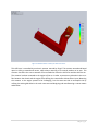
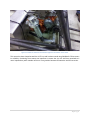
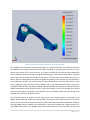
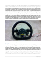
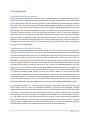
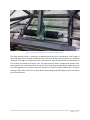
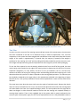
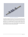
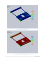
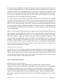
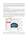
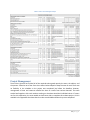
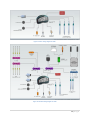
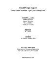
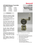
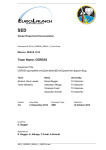
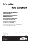
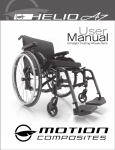
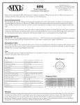
Team FSAE Driver Controls Performance Validation & Path Forward Final Report for MEEG401 12/1/2010 The goal of the fourth phase of the Senior Design process is to validate the design solution in order to demonstrate the performance viability of the systems. This has been accomplished by fully fabricating each component for the four different systems and sufficiently testing the finished product. For the FSAE sections, there were no plans for a prototype, but rather a finished set of systems. For Team Driver Controls, these systems included the Shifting System, the Steering system, the Pedal Box system, and the Data Acquisition system. The success of each of these systems is outline in this report. Table of Contents List of Figures ............................................................................................................................ 2 List of Tables ............................................................................................................................. 2 Executive Summary.................................................................................................................... 3 Shifting System.......................................................................................................................... 4 Updated Project Requirements ................................................................................................ 4 Demonstration of Viable Prototype........................................................................................... 5 Test Plan ............................................................................................................................... 9 Technical Path Forward..........................................................................................................10 Steering System........................................................................................................................11 Updated Project Requirements ...............................................................................................11 Demonstration of Viable Prototype..........................................................................................11 Test Plan ..............................................................................................................................13 Technical Path Forward..........................................................................................................14 Pedal System............................................................................................................................14 Updated Project Requirements ...............................................................................................14 Demonstration of Viable Prototype..........................................................................................14 Test Plan ..............................................................................................................................16 Technical Path Forward..........................................................................................................18 Data Acquisition System ............................................................................................................18 Updated Project Requirements ...............................................................................................18 Demonstration of Viable Prototype..........................................................................................19 Test Plan ..............................................................................................................................19 Technical Path Forward..........................................................................................................20 Projected Commercial Viability ...................................................................................................21 Cost Analysis ............................................................................................................................21 Project Management.................................................................................................................22 Appendix .................................................................................................................................23 1|Pa g e List of Figures Figure 1: Steering, Paddle Shifter, Dash unit, and Pedal System installed in chassis .............................. 3 Figure 2: FEA of custom shift lever (35 pounds to actuator mount).................................................... 5 Figure 3: Minimum factor of safety for shift lever is 8.92. ................................................................ 6 Figure 4: Actuator and shift lever mounted the engine and transmission in the chassis. ....................... 7 Figure 5: Finite element analysis testing of the actuator mount bracket. ............................................ 8 Figure 6: Steering wheel with paddles mounted. ............................................................................ 9 Figure 7: Steering rack and lower column support installed in chassis. ..............................................12 Figure 8: Steering wheel, upper mount (without gusset), paddles, and pedals in chassis. .....................13 Figure 9: Schematic view of adjustability system...........................................................................15 Figure 10: Stress Analysis of pedal system ....................................................................................17 Figure 11: Minimum factor of safety for the pedal system is 1.7.......................................................17 Figure 12: Screenshot of computer setup for AIM PISTA MXL dash. ..................................................20 Figure 13: Basic wiring diagram for dash.......................................................................................24 Figure 14: Detailed wiring diagram for dash. .................................................................................24 Figure 15: Wiring diagram to connect brake pressure sensor. ..........................................................25 List of Tables Table 1: What the dash will record and display. .............................................................................19 Table 2: Driver Controls Budget Analysis ......................................................................................22 2|Pa g e Executive Summary Formula SAE is a competition for college students to design and build a race car to represent their school. The car must follow the strict rules and regulations set forth by the organizer, SAE International, formerly the Society of Automotive Engineers. The vehicle must be an open-wheel, open-cockpit design employing 4 wheels that are not in a straight line. The wheelbase of the car (measured from ground contact to ground contact of the front and rear tires) must be at least 60 inches. The maximum engine displacement is limited to 610cc. In past seasons, the University of Delaware has relied on the SAE club to build the car; however, for the 2011 season, the school is utilizing four Senior Design groups to design and fabricate four major areas of the car. These four groups are the chassis, the suspension, the drivetrain, and driver controls. This paper summarizes the efforts of Team Driver Controls which was responsible for the car’s shifting, steering, pedal, and data acquisition systems. Figure 1: Steering, Paddle Shifter, Dash unit, and Pedal System installed in chassis The shifting system for this new car is electronically actuated and is controlled by the driver via paddles which rotate with the steering column and are mounted directly behind the steering wheel. This system has been successfully implemented by using an electric actuator, a control module, two custom made paddles, two spring-return rotary switches, and much custom brackets. This system meets all of the customer’s needs: reliable shifting of the sequential manual transmission, easy neutral engagement, and intuitive shift control. The system also meets all the metrics set forth by the team and the customer: at least 500 shifts between system maintenance, at least two square inches of driver-shifter interface area, and less than 6 pound in overall system weight. 3|Pa g e The steering system utilizes a 12:1 rack and pinion steering rack and a forged universal joint to transmit driver’s steering inputs into translation of the tie rods to steer the front wheels. Team Driver Controls was responsible for everything from the steering wheel to the ends of the steering rack, where the team interfaced with the Team Suspension. The final product features a support for both the upper steering column and the lower steering column to ensure proper alignment of the steering column with the input shaft to the rack to prevent premature wear. The system meets all of the customer’s needs: balanced steering, zero interference between tires and chassis or suspension components, and a removable steering wheel. All of the performance metrics have been met: angle of motionless travel limited to less than 7 degrees, less than 0.5pounds of force require turning the steering wheel with the driving wheels off of the ground, and less than 8 pounds of overall weight. The pedal box system features drill-operated adjustment for both quick and accurate adjustment of the pedal box position, comfortably accommodating the 95 th percentile male driver as well as the 5th percentile female driver. The aluminum frame is supported by a guide rail and the all-thread adjustment rod. The box will easily withstand the required 660 pounds of stopping force applied to the brake pedal, aiding in driver confidence and safety. All customer needs are met: all pedals function properly, the fore and aft brake bias is adjustable from the cockpit, and the pedals accommodate the described 90 percent population. All metrics for the system have been met or surpassed: strong enough to withstand 660 pounds of force, optimum range of pedal motion, at least 6 inches of adjustability, adjustability increments less than 0.5 inches, pedal height of at least 5 inches, and overall weight less than 6 pounds. The data acquisition system features the AIM PISTA MXL dash monitor and display from the previous car. The dash display pertinent information to the driver continuously without over-loading the driver with too much information. Only engaged gear, shift indicator lights, engine speed, and wheel speed are constantly shown to the driver. Other important information, such as fuel level and engine temperature, utilizes the available warning lights on the dash unit. Still, more data is collected and stored in the dash memory so that the team can analyze the car and the driver post-race. Team Driver Controls interfaced with Team Chassis to ensure that the dash is fully displayed above the steering wheel without extruding above the front cowl. With this, all customer needs and performance metrics are met. Shifting System Updated Project Requirements The requirements of the shifting system have not changed significantly since the last update. That is to say that the team must have designed and created a reliable means to shift the sequential manual transmission already present in the car, as well as an easy way to engage neutral and to have intuitive and ergonomic controls. Less driver effort is desirable for the customer and quicker shift time is an added plus, but not the first priority for the team. These requirements have been gauged using the following metrics and target values: a reliability of at least 5000 shifts between system service, a driver interface area of at least two square inches, and a weight of less than 6 pounds. 4|Pa g e Demonstration of Viable Prototype Team Driver Controls has managed to succeed in meeting all of the customer’s needs and constraints for this system. The fully realized system has been tested and installed into the car. Starting at the transmission, the system utilizes a custom shift lever to rotate the transmission’s sequential drum. This shift lever was designed to avoid any contact with the ground, engine, chain, or chassis member. The lever was made of aluminum so that the team could create a spline using the steel spline of the transmission. Extensive finite element analysis (FEA) was done to ensure that this lever does not break under repeated loading even considering the loss in material strength at the weld points as the part consists of three separate components. Reinforcement screws were added to connect the three parts of the lever to add strength at these weak points. Figure 2: FEA of custom shift lever (35 pounds to actuator mount). 5|Pa g e Figure 3: Minimum factor of safety for shift lever is 8.92. This shift lever is controlled by an electric actuator sourced by Pingel. This actuator was selected based upon its ability to extend and retract, while always returning to its neutral position on its own. This actuator also offers the correct amount of force needed to rotate the shift lever and thus shift the car. The actuator has been mounted to the engine of the car in order to prevent any vibration in the car or flex between the chassis and the engine from shifting the transmission without driver input. Mounting the actuator to the engine proved to be challenging, but the team was able to accomplish this by utilizing the existing bolt holes in the crank case cover and designing and manufacturing a custom mount and bracket. 6|Pa g e Figure 4: Actuator and shift lever mounted the engine and transmission in the chassis. This mount has been shaped around the oil fill cap and has been tested using SolidWork’s FEA to ensure its reliability. Positioning the actuator was important to ensure that it or the shift lever attached to it never impacted any other member of the car in any position between full extension and full retraction. 7|Pa g e Figure 5: Finite element analysis testing of the actuator mount bracket. The actuator uses a controller, also sourced by Pingel, to manage its functions. The controller consists of two MOSFETs that prevent the actuator from either extending or retracting more than once in a one second time interval. This is vital to the car as it helps to reduce the chance that a driver downshifts twice accidentally and over-revving the engine and destroying it. This essential safety factor is why the team made sure to include this controller in the system. The controller receives power from the car’s battery (which is recharged by the engine’s magneto) and sends it to the actuator at a rate of 36A for a 0.5 second time interval. This power rating has been compared with all of the other draws on the battery-magneto system and that system’s abilities and it was determined that draw is more than acceptable. With the fans, fuel pump, and data acquisition display all running, the car will be able to be shifted continuously around 90 times, which is more than enough. The car will be able to be shifted more than 500 times in a simulation of an endurance race. Five hundred shifts was the most any other team has ever shifted in an endurance event. The controller receives its signal from two spring return rotary switches which are attached to the paddle shifters mounted behind the steering wheel. Rotating the left paddle rotates the left switch which tells the controller to retract the actuator, which causes the transmission to downshift. Pulling on the right paddle causes an upshift in the transmission. This setup is intuitive and is what is using on F1style paddle shift systems. The paddles, which were custom made on a CNC mill, offer just over two 8|Pa g e square inches of interface area per paddle allowing different drivers to hold the steering wheel at different position and still be able to reach them. The paddles have also been anodized to give them a blue color, which in conjunction with the yellow quick release system on the steering wheel, represent the University of Delaware’s colors. The paddles and switches have been mounted to another custom bracket that is semi-permanently attached to the steering column. The setup was attached to the steering column instead of the steering wheel so that they would not interfere in the escape event, in which the driver must remove the steering wheel and escape from the car in less than five seconds. Putting the switches on the steering wheel would require either a fussy coiled wire hanging from the steering wheel or quick-release system that integrated the wires within. Though this last setup is the ideal solution, it costs nearly half of the team’s entire budget and the customer requested that we keep the current car’s quick-release system. The wires on the team’s solution will be neatly secured to the steering column with only enough play to allow for complete wheel rotation without any tangling. Figure 6: Steering wheel with paddles mounted. Test Plan In order to ensure the shifting system created by Team Driver Controls meets all of the metrics and target values agreed upon by the team and the customer, a test plan had to be generated. First, to test the overall weight of the system, all of the components were weighed. This included the actuator, controller, shift lever, switches, paddles, and all mounting brackets, but not the battery as it would be required of the car without electronic shift system. The total weight of the system was found to be just 5.8 pounds. This value is trusted, if not verified, by using two different scales and obtaining the same weight. This is better than the target value and demonstrates success of this goal. It is noted that the bulk of the weight comes from the actuator, though its weight is comparable to competitive actuators. 9|Pa g e Also, this system is lighter than if the team had gone with a pneumatically controlled system, which had been considered in the earlier design stages of the project. To ensure that the driver was easily able to control the shifting functions of the car, the team designed there paddles to have a high surface area so that they could be reached from if the driver is gripping the steering wheel at 11 and 1 o’clock or at 5 and 7 o’clock which are extreme positions for racing. The ideal hand location is 9 and 3 o’clock, which is reflected in how the steering wheel is molded. Simple measurements show that this target value is met as the paddles created are the same as those proposed previously. Further testing results will come when actual driver get the opportunity to drive the car and use the shifting system. These drivers should find that the paddles are quick comfortable and easy to operate. The early consensus from the SAE club reveals that all observers like and appreciate the paddles. Testing the reliability of the system fully requires extended use in the car. To date, the shifting system has been shifted 5000 times over a ten day period. Testing up to this target value for shifting ensures that the system will be reliable for the competition. Every shift that was tested proved to be a complete shift, guaranteeing that during the race, the car will shift as desired. Technical Path Forward Moving beyond the timeline of the Senior Design course, the shifting system requires no development work as the system is fully realized and fully functioning. What does need to be fabricated and installed in the car is a back-up mechanical shifting system that the advisor recommended. This was not originally required by the customer, but it is wise to have such a system in the event something fails at competition. All of the components for the system have been accounted for and considered with custom shift lever and electronic shift system. If the electronic shift system were to fail, the actuator would retract and extend freely as a push/pull cable took over as the shift actuator. This back-up system is quite simple and will be done by an SAE club member who also installed the mechanical shift system in the old, driver training car. Continued testing will be completed as the car is driven. One thing that can change is the amount of throw in the paddles. The switches allow for a full 36° of rotation to momentarily activate the switch, but the team has designed the mounts to allow for this rotation angle to be adjusted anywhere down to 5°. This ability to work for a variety of rotation angles and to only rely on the final 5° of travel to activate is why these particular switches were selected for the project. Driver feedback will allow the team to adjust this angle to best suit driver comfort and intuition. No maintenance is required of this system as all components are rated by their manufacturers as having life cycles in the hundreds of millions of cycles. Also, the components designed by the team do not require maintenance. Therefore, the system will be run to failure, which is not predicted to occur for more than ten competitive seasons. 10 | P a g e Steering System Updated Project Requirements The steering system requirements for the car have remained consistent throughout the design process. The steering system must be first and foremost balanced. The effort required of the driver to turn either left or right must be equal and as little as possible in order to effectively circumvent the tight autocross race track. Also, the front tires must not interfere with anything, specifically any suspension or chassis components. The customer also wanted the team to find a good tradeoff between quick steering and light steering. This is because the quick the steering is, the quicker the car responds to driver inputs, but the effort required increases. Finally, slop had to be decreased in order to meet FSAE competition requirement; that is to say that the total angle of motionless travel had to be less than seven degrees. The metrics and corresponding target values that define success for this system were: less than seven degrees of total motionless steering wheel travel, less than 0.5lbs of driver input to the perimeter of the steering wheel with the front wheel off of the ground for the front wheels to turn, and a total weight of the system less than eight pounds. Demonstration of Viable Prototype With the steering setup designed by Team Driver Controls, all of the metrics have been successfully met. Starting at the furthest point from the driver that the team was responsible for, the end of the steering rack were determined to be clevis ends. This decision was made with Team Suspension as having clevis ends on the steering rack and the rod ends on the tie rods made it easier for them in terms of adjustability. Collaboration with Team Suspension also helped to determine the total travel of the rack to prevent any tire impaction. Team Driver Controls was entirely responsible for determining the ratio of the steering rack and the overall steering ratio for the car given the suspension geometry. The team decided to use a 12:1 Stiletto steering rack sourced by Woodhaven Industries. With the rack placed 2.5” ahead of the wheel centerline, the overall steering ratio comes to 7.77:1, which means that for every 7.77 degrees of steering wheel rotation the front tires rotate 1 degree, or one full steering wheel rotation yields 47 degrees of tire rotation. The rack the car will use has a total rack travel limited to 3.5 inches which results in a total wheel rotation of 70 degrees (30 in either direction) and a total lock-tolock of the steering wheel of 1.5 turns. These specifications fall directly between what is recommended by an FSAE competition judge who suggested teams have an overall steering ratio between 5 and 10. The input of steering rack is a spline shaft and is connected to the lower steering column via a split clamp coupler that also came from Woodhaven Industries. The team has also designed a custom support bracket that keeps the lower steering column in perfect alignment with the rack input shaft. This support is easily bolted onto the steering rack housing so that perfect alignment was achievable, which would be practically impossible if the support were attached to any chassis member within the car. The support consists of two roller bearings that sit inside of a custom sleeve which is welded to a piece of square tubing that angles from the rack housing bolt holes up to the steering column. The lower steering column is positioned at 60° angle from the horizontal as the rack has strategically angled to limit the number of joints in the system to just one to prevent any unnecessary slop. 11 | P a g e Figure 7: Steering rack and lower column support installed in chassis. The lower steering column is attached to a forged universal joint that is positioned at a 140° angle to ensure the joint rotates smoothly and doesn’t bind. This puts the upper steering column at a 20° above horizontal. This angle was determined with Team Chassis in order to optimize the size and position of the roll hoop just ahead of the driver area. The upper steering column is supported by another roller bearing sleeve with is positioned from the top of the roll hoop using two lightweight angled tubes that were held together with a gusset, which also provides a location to mount the dash unit. The upper steering column utilizes the old car’s quick-release system designed by SPA Design to attach the column to the steering wheel. 12 | P a g e Figure 8: Steering wheel, upper mount (without gusset), paddles, and pedals in chassis. Test Plan In order to test the success of the steering system and how it meet all its measurement, the same tests that were conducted on the old car to determine areas in needs of improvement. First, all of the components in the system have been weighed with two different scales. Both scales show that the total weight of the system is approximately 7.5 pounds. Also, the majority (5 pounds) of the weight is attributed to the steering rack itself and the tubing and brackets needed to securely mount the rack. This weight was kept low to the ground to help lower the center of gravity and for easier packaging. To test the force required to turn the steering wheel with the front tires off of the ground, the team used a spring scale attached to the edge of the steering wheel to determine this input force. Since the suspension components, tie rods, wheels, and tires are not yet installed in the car, the force only measures the effects of turning the steering column and extending the ends of the steering rack. It was determined that this input force is about 0.4 pounds at the steering wheel perimeter. This value may not be completely compared to the target value or the measurement obtained in the beginning of project because the car is not yet fully assembled. This test will be repeated once a more accurate value can be obtained. The same issue arises when the team tried to test the angle of motionless travel. Because the wheels and tires cannot be installed on the car yet, the team cannot determine the amount the steering wheel will rotate before the front tires respond and begin motion. The team predicts that this angle will be about one degree in either direction based on the fact that the steering rack responds instantly to steering wheel rotation. There is only negligible slop in the system which is mostly attributed to the worn-out quick release spline. Again, this test can be repeated once the car is fully assembled in order to 13 | P a g e obtain more credible test results. Team Driver Controls is confident that these tests will prove the steering system will meet or exceed all the metrics. Technical Path Forward The path forward for the steering system is to continue testing the system as described above. Beyond this testing, there is little that must be done to maintain the steering system. With the additional aligning support, the most expensive component of the steering system, the steering rack, would be able to last for many competitive seasons without destroying the teeth of the rack and pinion unlike the unit in the current car. Still, the rack will be used until failure with no need to add or change lubrication. The other component of the system that could become worn is any one of the four bearings. Lubrication could be added to the bearings if an immediate solution is required, or they could easily be replaced given the low price. Pedal System Updated Project Requirements For the pedal cluster, the customer requirements were for the all of the pedals to function properly, for the brake bias to be adjustable remotely from the cockpit area, and that the positioning of the pedals be adjustable enough to accommodate both a 95 th percentile male and a 5th percentile female. The customer wanted an intuitive amount of pedal travel for modulation of the clutch, brake, and accelerator. Furthermore, the FSAE rules require that the pedal system feature an over-brake feature that cuts power when braking power is diminished, that the brakes act on all four wheels, that the brake system lock up all four wheel under competition testing, that the pedal cluster doesn’t extend below any frame member, and that the brake system is mechanical. These needs and wants were defined by the following metrics and target values: a total deflection of less than 1/8”, an overall strength to withstand 600 pounds of stopping force, six inches of adjustability, less than ½” between adjustment increments, a total weight of less than 6 pounds, and a pedal height of at least five inches. Demonstration of Viable Prototype The pedal system created by Team Driver Controls utilizes the brake pedal and master cylinders from the current car as recommended by the customer and advisor. The pedal covers were sources from a car that was ran several seasons ago. The rest of the pedal system show have completely fabricated by the team in the university’s machine shop. The solution features a frame that supports the three pedals and the cables which run to them. The frame is adjusted by spinning the threaded rod on the right and is guided along the steel rod on the left. The guide rail remains stationary and is welded to a square cross member at the front of the chassis as well as to another square cross member further back into the chassis. Steel inserts were added to the inside of cross member to add support and to aid in alignment of the rail. The pedal frame simply slides along this member thus no load is taken. All of the braking forces are transmitted to the threaded rod. Thorough analysis was conducted to ensure that this member could withstand the high loading. The pedal frame actually moves along the threaded rod when the rod is spun by using two square threaded nuts welded onto the frame. 14 | P a g e Figure 9: Schematic view of adjustability system The threaded rod is supported on both ends by a steel insert in the cross member and free rotation is encouraged by brass bushings in each support. Two nuts are locked together on each side of the cross members to prevent the threaded rod from sliding out of the supports. To quickly and precisely adjust the pedal position, a battery-operated drill is attached to the rearmost locking nut and spun to move the pedal frame for or aft. Total pedal adjustment is five inches due to chassis constraints and the positioning of the master cylinder lines. The team has also added protected boots to the guide rail and the threaded adjustment rod so that no dust or debris accumulates. This will maintain the pedal system’s lubrication and encourage smoother motion during adjustment. These boots also protect operator’s hands when they reach into the cockpit to adjust the pedals. 15 | P a g e Figure 10: Adjustable pedal cluster mounted in chassis (protective boots removed). Test Plan There were several metrics to test for the pedal system. First, to ensure that the pedal system will withstand the high braking forces without failing during a competition, 800 pounds of force were applied to the pedal frame with the entire setup welded into the chassis. To do this, two people applied as much force as they could to the pedal frame. The same two people then pressed as hard as possible with their backs against a wall against two different bathroom scales. The total of these measurements came to 815 pounds. This test procedure was recommended by an FSAE design judge. There was no noticeable deflection and the system held up well. The team is confident that the pedal system will hold up at competition as well. 16 | P a g e Figure 10: Stress Analysis of pedal system Figure 11: Minimum factor of safety for the pedal system is 1.7. 17 | P a g e To test the amount of adjustment available with the system, the team simply positioned the pedals as far forward as possible and then as far back as possible. The difference between these two positions is eight inches. Furthermore, we have positioned a 6’4’’ male and a 5’ female into the cockpit area of the car. The 6’4” male is 2” taller than the 95 th percentile male, but the 5’ female is one inch taller than a 5 th percentile male. Regardless, both were able to fit inside of the car and comfortably reach the pedals. This represents success in the amount of adjustability required. To ensure the proper range of motion of each pedal, the position of the cable mounts was calculated considering the extension of each cable. This is why the clutch cable is connected to the clutch pedal at a higher point than the throttle cable is connected to the accelerator. The total travel for the pedals is 12° and 25° for the clutch and throttle, respectively. The height of the pedals was designed around the existing brake pedal, which is a professional Wilwood unit. This led to a seven inch pedal height so that all of the pedals were approximately the same height. It was also important to make sure the pedals were in the same plane. Finally, to test the weight of the pedal system, all components were weighed using two different scales before the parts were assembled and installed in the car. Since one guide rail was omitted from the original design to allow the adjustment screw to lie in the same plane as the pedal frame, some weight was saved. However, weight was added by using two steel cross members as opposed to the cantilevered tabs the original design specified. This weight was justified though for it vastly superior load capabilities. The total weight of the pedal system came to a little over seven pounds. Though this does not meet the target value for the team, the target value came from a Tilton pedal assembly that did not include the supports necessary to mount the assembly. If only the pedals and frame are considered, the system meets the weight metric at 5.5 pounds. Technical Path Forward In order for the car to be ready for competition, the over-brake feature and the brake light must be added to the system. These are simple aspects of the overall system that can be easily added by the SAE club once senior design work ends. All other aspects of the pedal system have been completed. Other than maintaining the proper amount of fluid in the maser cylinders and brake lines, the system requires only that anti-seize lubricant to the threaded rod as needed. Data Acquisition System Updated Project Requirements As of recent there have been changes made to the scope of the project in respect to the Data Acquisition system. Due to the fact that the overall budget of the entire project had no extra funding for the additional required sensors, the steering angle sensor and brake pressure sensors could not be purchased out of the senior design account. It was assumed that the FSAE club would purchase these sensors out of their budget; however they too lack sufficient funding. Therefore, instead of installing these sensors, there will be specified channels and LEDs left available for them whenever they are finally purchased. 18 | P a g e Demonstration of Viable Prototype The Data Acquisition system was not designed, but rather optimized to improve driver ability and understanding for instances in which the car has problems. It was very important to decide which sensors need to be displayed, either by warning lights or on the dash screen. The information presented by warning lights is the water temperature, oil pressure and temperature, brake pressure, fuel level and battery voltage. Information displayed directly on the dash screen is the engine speed, current gear, wheel speed, angular steering column position, proper acceleration and skid detection, manifold pressure, exhaust gas temperature, air charge temperature and vehicle brake pressure. The system will also alert the driver when to shift via the red, yellow and green lights at the top of the unit. All of this information will be recorded while the car is running, and can be used later to evaluate the driver’s performance, as well as the car’s performance. By consistently testing drivers, the data acquisition system will provide the information needed to determine the most experienced driver and also maximize their ability to handle the car. One example of this is the capability to record the pressure required to completely lock up the front and rear brakes, the team evaluates how much to adjust the current pressure, and the driver makes the adjustment via the remote brake bias knob on the data acquisition unit from their seat. Table 1: What the dash will record and display. Test Plan In order to determine if the data acquisition system is successful, Team Driver Controls will conduct two tests. The first will be conducted from the cockpit. Both a 95 th percentile male and a 5th percentile female will sit in the seat area of the car. If the driver is able to see the entire dash display and reach the 19 | P a g e buttons on the unit, the car will be positioned correctly. The continual display on the dash will include the tachometer, current gear selected, speedometer, and shift indicator light so that the driver has all requisite information to drive the car. The team must also ensure that all warning lights work properly. The second test the team will conduct is with the dash unit out of the car and connected to the computer. So long as all the desired information is recorded, the dash unit will be successful compared to the metrics set for it. Technical Path Forward The Data Acquisition unit is secured to the car at the present time; however it is not yet configured to record information from the car’s ECU. The system will be interfaced with the ECU using a CAN cable to sample data that the ECU outputs. In order to complete this connection, the CAN cable must attach to the connectors on the gauge backside. It is important, however, to refer to the ECU user manual to be sure which pins are used and which cable connects to which pin. Once the system is correctly connected, it will need to be configured to record the required information. This step is actually quite simple and will only require background knowledge of the program, Race Studio 2. Pages 21-36 of the instruction manual (see appendix) give a very thorough and detailed process on how to set and select a configuration, set MXL channels, set the system configuration, and finally how to transmit the configuration via the USB connection. After the system is properly installed and configured, it can be put to use immediately. Figure 12: Screenshot of computer setup for AIM PISTA MXL dash. The customer and advisor both requested that the team install a brake pressure sensor and a steering angle sensor so that driver performance could be tracked and analyzed after racing. However, these 20 | P a g e sensors were deemed by all parties to be outside of the team’s budget. The sensors were to be donated by the University of Delaware Mechanical Engineering department, but these items have yet to be approved. Once they are approved and purchased, they will be able to be installed easily given the included instructions and hardware. Projected Commercial Viability One of the design aspects behind the Formula SAE competition is that each car is designed for a customer. The car designed by the University of Delaware Mechanical Engineering FSAE Senior Design teams is no different. The main customers for the total car are the SAE club to use at competition, Dr. Timmins as the SAE club advisor, and the individual customers that each of the four teams had. The car was designed for the wants and needs of these customers. It is likely that the car will appeal to a variety of customers as the underlying design intentions are similar for all racers. They want their race cars to go fast, handle well, and be comfortable to driver. The UDFSAE design teams have accomplished this with this car. The commercial viability of the individual components of the car; however, is more limited as each is customized to this specific car. Therefore, the car as a whole will likely appeal to potential customer, but the individual subsystems on their own will not. Furthermore, the commercial viability of the car will become more present when the team takes the car to competition. How the car scores in both the static and dynamics events at competition will further defines the car’s commercial viability. Cost Analysis In an unlikely event, Team Driver Controls has actually finished the project below its projected total cost. With everything tallied, the total cost of the project effort came to $945.31, which is about $54 below the hard budget limit set at $1000.00 and about $44 less than the team projected in Phase 3. This reduction in total cost is attributed to paying less for shipping than expected, getting a small discount on the steering rack, and combining suppliers when possible to save on shipping costs. It must be noted that the team was only able to meet the project budget by utilizing the materials available at the University of Delaware’s machine shop. The machinist here, Mr. Beard, allowed the team to use shop material at a price based on the amount used. For example, by using stock aluminum bar for the pedal box, the team was able to only pay for the amount used at McMaster-Carr prices as opposed to buying six feet of identical aluminum bar when only say 14” were needed. Furthermore, using the AIM PISTA dash from the old car and having the brake pressure sensor and the steering angle sensor donated to the club during Winter Session, saved a tremendous amount of money for Team Driver Controls. A complete breakdown of the cost of the entire project is shown below. 21 | P a g e Table 2: Driver Controls Budget Analysis Project Management Team Driver Controls has finished all of the required tasks agreed upon by the team, the advisor, and the sponsor. Effective use of the Gantt chart shown below helped to keep the team on task. There was no flexibility in the schedule as the project was completed just before the deadline; however, management of time and resources allowed the time to recover from various obstacles. The team worked well together with each member working on what best suited their individual talents. If it were not for this cooperation, the team would not have been able to complete this arduous project. A link is available in the Appendix that shows how the tasks were divided and when they were completed. 22 | P a g e Appendix Link to full Shift Lever Stress Analysis Report (Also available in the team’s GoogleDocs “Phase Reports” folder and Sakai) Link to full Pedal Box Stress Analysis Report (Also Available in the team’s GoogleDoc “Phase Reports” folder and Sakai) Link to Project Management Plan (Also available in the team’s GoogleDocs “Updates” folder and Sakai) Link to Instruction Manual for AIM PISTA MXL: instruction manual Details relevant to this project: 2 – How to install and power MXL To install MXL in your car or motorcycle: Install MXL vertically with the display perpendicular to vehicle direction of motion in order to correctly measure the lateral g-force using the internal accelerometer4. Choose a location where the display unit is not in contact with oil or fuel. Ensure that the system is not installed too close to heat sources. Protect MXL from vibration: use the included anti-vibration mountings; Avoid rigid connections between the display unit and the chassis: use antivibration mountings (Silent Blocks). To power MXL: Connect MXL to an external 9-15 VDC power source (the vehicle battery, for instance). Do not exceed these limits. Connect the red wire to the battery’s positive pole (+) and the black one to the negative pole (-). MXL is powered by the vehicle master switch. 5 – How to connect MXL to the ECU Your MXL can be interfaced with the engine computer (ECU) using an RS232 serial cable or a CAN cable to sample data out coming from the ECU. To connect your MXL to the ECU, please use a serial RS232 or a CAN cable and connect it to the connectors on the gauge backside. If you have an ECU communicating through the CAN bus and you have our stock cable, they are already labelled; otherwise connect CAN +, CAN - and GND to your ECU pins. To know which pins support which cable, please refer to your ECU user manual. If you have an ECU communicating through an RS232 protocol, the standard connection is: cable labelled RS 232 RX with the ECU TX cable labelled GND with ECU GND PLEASE REFER TO YOUR ECU USER MANUAL TO BE SURE W HICH PINS ARE USED AND WHICH CABLE IS TO BE CONNECTED TO WHICH PIN. To know if your ECU is supported by MXL and for more information about MXLECU connections, please refer always to our website: www.aim-sportline.com. As ECU manufacturers continually update their products, refer to their website for the latest information, which may conflict with this manual. 23 | P a g e Figure 13: Basic wiring diagram for dash. Figure 14: Detailed wiring diagram for dash. 24 | P a g e Figure 15: Wiring diagram to connect brake pressure sensor. 25 | P a g e