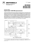
1
O P E R AT I N G I N S T R U C T I O N S OLM200 – PROFINET IO Linear measurement sensor EN Applicable to firmware ≥ V2.1 Operating Instructions OLM200 This document is protected by the law of copyright, whereby all rights established therein remain with the company SICK AG. Reproduction of this document or parts of this document is only permissible within the limits of the legal determination of Copyright Law. Alteration or abridgement of the document is not permitted without the explicit written approval of the company SICK AG. Note 2 SICK uses standard IP technology in its products, such as I/O link and industrial PCs. The emphasis is placed on availability of products and services. SICK always assumes that the integrity and the confidentiality of the data and rights which are affected by the use of the aforementioned products are ensured by the customer. In any case, appropriate security measures, such as network separation, fire walls, virus protection or patch management, are always to be taken by the customer, depending on the situation. © SICK AG • Advanced Industrial Sensors • Germany • Subject to change without notice 8014962/2011-04-26 Operating Instructions Contents OLM200 Contents 8014962/2011-04-26 1 About this document ......................................................................................................5 1.1 Function of this document....................................................................................5 1.2 Information depth .................................................................................................5 1.3 Scope .....................................................................................................................5 1.4 Symbols used ........................................................................................................6 2 Product description ........................................................................................................7 2.1 Safety notes...........................................................................................................7 2.1.1 Safety standard ...................................................................................7 2.1.2 Correct use ..........................................................................................7 2.1.3 Areas of application ............................................................................7 2.2 Device designation and corresponding bar code tapes .....................................7 2.2.1 Type plate ............................................................................................8 2.3 Principle of operation............................................................................................8 2.4 Control marks........................................................................................................9 2.4.1 Control marks for operation ...............................................................9 3 Mounting ...................................................................................................................... 10 3.1 Bar code tape mounting .................................................................................... 10 3.1.1 General data for the bar code tape................................................. 10 3.1.2 Mounting of the bar code tape at horizontal curves ...................... 12 3.1.3 Mounting of the bar code tape on vertical curves ......................... 13 3.2 Sensor mounting................................................................................................ 14 4 Electrical installation .................................................................................................. 16 4.1 Position of the electrical plug connections....................................................... 16 4.1.1 Ethernet interface ............................................................................ 16 4.1.2 Supply voltage connection............................................................... 17 4.2 General notes for electrical installation............................................................ 17 4.3 Wiring notes........................................................................................................ 17 5 Commissioning............................................................................................................. 19 5.1 Device configuration .......................................................................................... 19 5.1.1 Import device description file (GSD) ............................................... 19 5.1.2 Configuring the participants ............................................................ 19 5.1.3 Parameterization.............................................................................. 20 5.1.4 Factory setting.................................................................................. 20 5.2 Ethernet parameter list and factory settings.................................................... 20 5.3 PROFIBUS IO interface....................................................................................... 22 5.3.1 Nomenclature................................................................................... 22 5.3.2 Description of PROFNETI modules for configuration and I/O data................................................................................................... 22 5.3.3 Module 1: “Position/i2w” ................................................................ 26 5.3.4 Module 2: “Position/i1w” ................................................................ 27 5.3.5 Module 3: “Speed/i2w” ................................................................... 27 5.3.6 Module 4: “Position/i2w, Speed/i2w” ............................................ 28 5.3.7 Module 5: “Position/i2w, Preset dyn/o2w”.................................... 29 5.3.8 Module 10: “Status/i1b” ................................................................. 30 5.3.9 Module 12: “Label/i3b”, “res/1b” .................................................. 31 5.3.10 Module 13: “Temp/i1b, Level/i2b, res/i2b” .................................. 31 5.3.11 Module 20: “MF1 Output Q”............................................................ 32 5.3.12 Module 21: “MF2 Input”.................................................................. 33 5.3.13 Module 22: “Preset stat and Offset”............................................... 34 © SICK AG • Advanced Industrial Sensors • Germany • Subject to change without notice 3 Operating Instructions OLM200 5.3.14 5.3.15 5.3.16 5.3.17 5.3.18 5.3.19 Module 30: “Serial no/i8b”.............................................................. 34 Module 31: “Product code/i14b” .................................................... 34 Module 32: “Version HW/i8b” ......................................................... 35 Module 33: “Version FPGA/i10w” ................................................... 35 Module 34: “Version μC/i10w” ....................................................... 35 Module 35: “Version μC2/i10w” ..................................................... 36 6 Maintenance................................................................................................................. 37 7 Technical data .............................................................................................................. 38 7.1 Data sheet OLM200 – PROFINET IO ................................................................. 38 7.2 Data sheet bar code tape .................................................................................. 40 7.3 Dimensional drawing.......................................................................................... 41 7.4 Accessories ......................................................................................................... 42 7.4.1 Plug connectors and cables............................................................. 42 7.4.2 Bar code tape ................................................................................... 44 7.4.3 Bar code tape printing...................................................................... 45 7.4.4 Order notes and variants of the bar code tape............................... 45 7.4.5 Bar code tape repair kit.................................................................... 49 7.4.6 Blank labels for repair codes or control marks............................... 49 7.4.7 Sliding nuts ....................................................................................... 49 8 Error tables and countermeasures ............................................................................. 50 8.1 Device errors and warnings ............................................................................... 50 8.2 Communication error.......................................................................................... 51 8.2.1 Ethernet errors.................................................................................. 51 8.2.2 PROFINET IO errors........................................................................... 51 9 Repair............................................................................................................................ 52 9.1 Repair barcode tape........................................................................................... 52 10 Appendix ....................................................................................................................... 53 10.1 List of figures ...................................................................................................... 53 10.2 List of tables ....................................................................................................... 54 4 © SICK AG • Advanced Industrial Sensors • Germany • Subject to change without notice 8014962/2011-04-26 About this document Operating Instructions Chapter 1 OLM200 1 About this document Please read through this chapter carefully before you use the documentation and work with the linear measurement sensor OLM200. 1.1 Function of this document This operating instruction instructs the technical personnel of the machine manufacturer or machine owner in safe mounting, configuration, electrical installation, commissioning as well as operation and maintenance of the linear measurement sensor OLM200, and also the associated bar code tape. This operating instruction does not provide information about operation of the machine in which the linear measurement sensor OLM200 is or will be integrated. For information about this, refer to the operating instruction of the machine. 1.2 Information depth This operating instruction contains information about the linear measurement sensor OLM200 on the following topics: Device designation Mounting Electrical installation Commissioning and configuration Fault tables and counter measures Technical data Accessories All official and statutory regulations governing operation of the linear measurement sensor OLM200 must be complied with. Note Please also refer to the website at: www.mysick.com/en/OLM200 There, one can find: available control codes and position codes for download as a PDF file, sample applications, a list of FAQs for the linear measurement sensor OLM200, SOPAS Engineering Tool for configuration, information about software updates, Device description file GSD. 1.3 Note 8014962/2011-04-26 Scope This operating instruction applies to the linear measurement sensor OLM200. © SICK AG • Advanced Industrial Sensors • Germany • Subject to change without notice 5 About this document Chapter 1 Operating Instructions OLM200 1.4 Note WARNING 6 Symbols used Notes inform you about special aspects of the device. Warning! A warning refers to specific or potential dangers. This is intended to protect you against accidents. Read the warnings carefully and comply with them! © SICK AG • Advanced Industrial Sensors • Germany • Subject to change without notice 8014962/2011-04-26 Product description Operating Instructions Chapter 2 OLM200 2 Product description This chapter contains information about the special properties of the linear measurement sensor OLM200. It describes the construction and operating principle of the device, especially the various operating modes. Always read this chapter before mounting, installing or operating the device. 2.1 Safety notes 2.1.1 Safety standard The linear measurement sensor OLM200 has been developed, produced and tested in accordance with the applicable safety standards. It is in accordance with the state of the art. The radiation safety has been evaluated based on the DIN EN 62471 standard, “Photobiological safety of lamps and lamp systems”. It is allocated to the “free group”, i.e. safety of the eyes and the skin against radiation is guaranteed at all times assuming the device is used correctly (in particular, this implies not opening the device). 2.1.2 Correct use The linear measurement sensor OLM200 is an opto-electronic sensor and is used for positioning of a movement unit by means of a bar code tape. Protection of the operating personnel and of the device is not guaranteed if the device is not used in accordance with its correct use. WARNING 2.1.3 Areas of application The linear measurement sensor OLM200 is suitable for the following areas of application: automated high-bay warehouse, positioning of overhead conveyors, curve-going stackers, turning rings/tables, shuttles, applications in which movable devices need to be positioned relative to a reference. 2.2 Tab. 1: Device designation Device designation and corresponding bar code tapes Data interface Device designation Part no. Bar code width Reading distance PROFINET IO OLM200-1009 1058126 30 mm 100 mm ± 20 mm Note Accessories available for the OLM200-xx0x variants are the appropriate bar code tapes with a bar code width of 30 mm and a tape height of 30 mm or 40 mm. Note A bar code tape with a height of 30 mm is sufficient in applications in which the linear measurement sensor OLM200 does not exceed a tolerance of ± 3.5 mm perpendicular to the transport direction. The bar code tape with a height of 40 mm permits a tolerance of up to ± 8.5 mm. 8014962/2011-04-26 © SICK AG • Advanced Industrial Sensors • Germany • Subject to change without notice 7 Product description Chapter 2 Operating Instructions OLM200 2.2.1 Type plate Fig. 1: Type plate Device Designation OLM200-1009 1058126 1022 1234 MAC OF:3B:65:AC:2E:08 Production date: YYWW (e. g. year 2010, calendar week 22) + serial number 2.3 Principle of operation The linear measurement sensor OLM200 is a sensor that can measure traverse paths up to 10 km without moving parts. The sensor determines its position via a bar code tape attached along the traverse path and uses a visible, red LED beam to do this. By reading the bar codes that are printed on the bar code tape at intervals of 3 cm (OLM200–xx0x), the linear measurement sensor OLM200 determines the absolute position and outputs this via an interface. Traverse speeds of up to 10 m/s are possible with a repeatability of 0.15 mm. On startup, the linear measurement sensor OLM200 initially detects its alignment in relation to the bar code tape (0° or 180°). The sensor automatically adapts itself to the alignment that is detected, and starts outputting position values. If there are no bar codes in the field of view when the sensor is started up, the sensor selects the last known orientation of the bar code tape. The sensor starts position values output as soon as bar codes with the expected orientation are located in the field of view. Error F4 and the measured value “0” are output if an unexpected alignment is detected, and this also applies if the alignment is changed along the traverse path. In such a case, position values are not output until after the supply voltage has been interrupted and the new alignment has been detected successfully. Note The tape orientation is assumed to be 0° in the delivery state. Note If the bar code tape is mounted in the entire system with an alignment of 180° in relation to the sensor, it is necessary to ensure that the bar code tape is located in the field of view when the sensor is started up for the first time. If the linear measurement sensor OLM200 detects an error condition while in motion (e.g. no bar code tape or bar code tape defective), this is initially suppressed and extrapolated measured values are output. The extrapolation time depends on the measured value history and is max. 160 ms. The extrapolation time can be set by control marks or via SOPAS ET (see page 21, parameter "Extrapolation time"). The measured value “0” is output if the error status is present or longer or exists right from switching on. Individual faulty bar codes do not have any effect on the measured value. Error statuses can be interrogated via the data interface. Alternatively, the SOPAS ET software is available for this via the Ethernet configuration interface. 8 © SICK AG • Advanced Industrial Sensors • Germany • Subject to change without notice 8014962/2011-04-26 Product description Operating Instructions Chapter 2 OLM200 Fig. 2: Schematic representation of the mode of function OLM200 2.4 Note Control marks The control marks are available for download and subsequent print at www.mysick.com/en/OLM200. 2.4.1 Control marks for operation If required, control marks can be stuck onto the bar code tape at selected points (e.g. switches). When doing this, make sure that the cut markings of the control mark are congruent with the cut markings of the position bar code that has been stuck over. Control marks transmit specific information to the linear measurement sensor OLM200. The information on a control mark consists of a letter (A, B, C, D or Z) followed by two digits (0 … 9). The control marks are available for download from www.mysick.com/en/OLM200, and can then be printed out. The control marks Q00 and Q01 control the switching output of the device. In this case, Q01 sets the switching output to active. Q00 sets the switching output to inactive. All other control marks are output via the PROFINET IO as ASCII hex values. The control mark must be interpreted byte-by-byte as ASCII characters. In this case, the most recently read control mark is always output every cycle. Example: Control mark A98 corresponds to 0x41, 0x39, 0x38 8014962/2011-04-26 Note In order to obtain a continuous distance value, it is necessary to ensure that there is a position code directly before or directly after the control mark. Note Only one control mark may be within the field of view at any given time. Therefore, a minimum of two bar codes must be placed between successive control marks. © SICK AG • Advanced Industrial Sensors • Germany • Subject to change without notice 9 Mounting Chapter 3 Operating Instructions OLM200 3 Mounting This chapter describes how to prepare and perform the mounting of the bar code tape and the linear measurement sensor OLM200. Note Illustrations and dimension values not in brackets apply to the 30 mm bar code width. 3.1 Bar code tape mounting 3.1.1 General data for the bar code tape Bar code tapes have a nominal length of 20 m; they are supplied rolled-up with the smallest number on the outside. The particular measuring ranges are selected so that successive bar code tapes can be placed against one another without gaps. The roll sequence number is located on the bar code tapes to make it easier to maintain the correct sequence. Bar code tapes with customer specific range start with the roll sequence number “1”, independent of the desired starting code. Fig. 3: Example for roll 1, measuring range 0 to 20 m 5324069 1024 000000 10 1 000003 000006 Measuring range [m] from to Roll sequence number Code Start Code End 0 20 1 (see Fig. 3) 000000 002001 20 40 2 002004 004002 40 60 3 004005 006000 60 80 4 006003 008001 80 100 5 008004 010002 100 120 6 010005 012000 120 140 7 012003 014001 140 160 8 014004 016002 160 180 9 016005 018000 180 200 10 018003 020001 200 220 11 020004 022002 220 240 12 022005 024000 240 260 13 024003 026001 260 280 14 026004 028002 280 300 15 028005 030000 300 320 16 030003 032001 320 340 17 032004 034002 340 360 18 034005 036000 360 380 19 036003 038001 380 400 20 038004 040002 400 420 21 040005 042000 420 440 22 042003 044001 440 460 23 044004 046002 © SICK AG • Advanced Industrial Sensors • Germany • Subject to change without notice 8014962/2011-04-26 Operating Instructions Mounting Chapter 3 OLM200 Measuring range [m] from to Roll sequence number Code Start Code End 460 480 24 046005 048000 480 500 25 048003 050001 The orientation of the bar code tape in relation to the sensor must remain the same throughout the entire traverse path (alignment always 0° or always 180° in relation to the sensor). Align the bar code tape with a reference edge (e.g. rail) of the traverse path and stick this onto the smooth, dry surface that is free from grease and dust, without any tension, folds or creases. It is possible to stick the tape over small expansion joints and minor points of unevenness. In the case of unevenness or gaps which would cause the bar code tape to be significantly distorted were they to be stuck over, it is possible to cut out an individual bar code at the corresponding cut marks. To ensure optimum linearity, the distance between the two cut marks at the resulting gap must be 30 mm. At least two successive bar codes must follow after a gap. It is recommended that self-adhesive, cut-to-length blank labels should be stuck over the gap in order to allow it to be traversed without problems (see section 7.4 “Accessories”). Fig. 4: Cut mark of the bar code tape 000015 000018 000021 000024 000027 cut mark 30 mm (40 mm) Fig. 5: Gap in the cut-open bar code tape gap 000015 000018 000021 000024 000027 cut mark A sequence of bar code tapes without successive measuring ranges is not allowed, otherwise a continuous position cannot be indicated. In case of discontinuation (e.g. at track changes), the linear measurement sensor OLM200 outputs a corresponding jump in the position value as soon as at least two successive bar codes have been detected in the new measuring range. The linear measurement sensor OLM200 cannot output any negative position values. Therefore, in applications in which it is necessary to go below the “0 cm” position (e.g. turntables, track changes), it is recommended not to use the measuring range 0 to 20 m, or else to remove the first two bar codes “0 cm” and “3 cm”. Note 8014962/2011-04-26 Affix the bar code tape as near as possible to the vertical in order to avoid dust buildups. © SICK AG • Advanced Industrial Sensors • Germany • Subject to change without notice 11 Mounting Chapter 3 Operating Instructions OLM200 surface Fig. 6: Vertical bar code tape mounting bar code tape Note Avoid strong external light reflections striking the bar code tape. 3.1.2 Mounting of the bar code tape at horizontal curves A minimum radius must be complied with for horizontal curves. This depends on the mounting position of the sensor. Generally the linear measurement sensor OLM200 should be mounted preferably in the axis of rotation. Tangential distances, referred to below as L, leading to the sensor swiveling in or out during the course of a curve mean that larger curve radii are required. This applies both to outer and inner radii. Fig. 7: Tangential distance L when cornering 000015 000018 000021 Rmin a L OLM Vehicle Legend: Rmin = Minimum radius L = Tangential distance when cornering a = Reading distance 12 © SICK AG • Advanced Industrial Sensors • Germany • Subject to change without notice 8014962/2011-04-26 Operating Instructions Mounting Chapter 3 OLM200 Fig. 8: Minimum curve radius Rmin depending on the tangential distance L Log. scale; minimum curve radius Rmin in m 100 10 1 100 mm separation of sensor and tape 90 to 110 mm separation of sensor and tape 0,5 0 3.1.3 100 200 300 400 500 600 Tangential distance L in mm 700 800 900 1000 Mounting of the bar code tape on vertical curves In order to attach the bar code tape along a vertical curve, cut into the bar code tape at the cut marks and fan it out. The maximum angle is not allowed to exceed 3°. This corresponds to a gap d of 1.5 mm or 2 mm (with 30 mm or 40 mm high bar code tape, respectively). This produces a minimum radius of 500 mm. The voids created by fanning open should not have a shiny surface, in order to ensure an optimum functional reserve. Fig. 9: Vertical curves 21 Rmin 00 5324069 00 1 1024 018 000 000015 d 8014962/2011-04-26 Open items must be taped off with blank labels (see section 7.4 “Accessories”). © SICK AG • Advanced Industrial Sensors • Germany • Subject to change without notice 13 Mounting Chapter 3 Operating Instructions OLM200 Note Make sure that the bar code tape is always in the field of view of the linear measurement sensor OLM200 along a vertical curve. The mounting location of the OLM200 should therefore be selected so that its traverse path runs parallel to the linear axis of the bar code tape. If, as a deviation from this, the OLM200 is mounted with a tangential distance from the axis of rotation, this will result in swiveling of the sensor and the bar code tape will move out of the field of view. Note Only restricted accuracy and reproducibility are possible with a vertical curve. 3.2 Sensor mounting The linear measurement sensor OLM200 can be mounted either using the six holes in the housing or the T-slots on the back, using sliding nuts (see section 7.4 “Accessories”). To ensure optimum reading results and the greatest possible functional reserve, mount the linear measurement sensor OLM200 at a distance of 100 mm from the bar code tape and align it at right angles to the bar code tape. The sensor's depth of field is ± 20 mm. power status on Fig. 10: Mounting distances OLM200 (3.94 0.79) Note 42 mm (1.65) 47 mm (1.85) 40 mm (1.57) 30 mm (1.18) A distance of 47 mm or 42 mm must be maintained between the bottom edge of the housing and the bottom edge of the SICK bar code tape. In particular in curves, take care to maintain a distance of 100 mm ± 20 mm from the bar code tape. If optimally aligned, the two alignment marks on the front of the OLM200 are located in the vertical middle of the bar code tape, so that the red luminous row running from the top left to the bottom right is vertically centered on the bar code bar (see Fig. 11). This centering must be within a tolerance of ± 3.5 mm or ± 8.5 mm respectively for the 30 mm or 40 mm height SICK bar code tape. 14 © SICK AG • Advanced Industrial Sensors • Germany • Subject to change without notice 8014962/2011-04-26 Mounting Operating Instructions Chapter 3 OLM200 Fig. 11: Vertical alignment OLM200 Alignment mark When two sensors are operated next to one another, it is necessary to maintain a minimum gap between the two sensors of 120 mm. At curves, make sure that the sensor is mounted as close as possible to the axis of rotation. For information about the minimum radii at curves, refer to section 3.1.2 “Mounting of the bar code tape at horizontal curves” on page 12. Note The sensor must be mounted in a way that no objects are within the field of view, obstructing a clear view of the bar code tape. Fig. 12: Field of view of the OLM200 Reading distance OLM200-xx0x ~ 190 120 110 ~ 165 100 90 ~ 145 80 70 60 50 40 30.0° 30 30.0° 20 10 All dimensions in mm (inch) 8014962/2011-04-26 © SICK AG • Advanced Industrial Sensors • Germany • Subject to change without notice 15 Electrical installation Chapter 4 Operating Instructions OLM200 4 Electrical installation Secure data transmission is possible when using shielded cables with twisted-pair wires. A correct and complete shield concept is required for trouble-free function. Specifically, it is necessary to ensure that the cable shield contacts the control cabinet and the linear measurement sensor OLM200 at both ends. The cable shield of the cables with terminals (see section 7.4 “Accessories” on page 42) is connected to the knurled nut and the functional earth connection pin, and therefore to the sensor housing. Equipotential bonding currents must be prevented from flowing along the cable shield by taking suitable measures. 4.1 Position of the electrical plug connections The position of the electrical connections can be seen in the following illustration. Fig. 13: Connections of the OLM200 PROFINET IO 1 2 Port 1 Port 2 3 4 Ethernet, socket M12, 4-pin Ethernet, socket M12, 4-pin not connected Device connection (supply voltage), plug M12, 5-pin 4.1.1 Ethernet interface The OLM200-xxx9 is equipped with two Ethernet interfaces. They serve communication via PROFINET IO and diagnosis and parameterization via SOPAS ET. The two interfaces have equal priorities and are internally connected to one switch. Fig. 14: Connection diagram Ethernet / Ethernet interface 1/2 3 4 2 1 Connect the OLM200 to the network via Ethernet connection lines. If the network is not forwarded to another network participant, connection to one of the Ethernet female connectors is sufficient. Close the female connectors not in use with a cover or a blind plug. 16 © SICK AG • Advanced Industrial Sensors • Germany • Subject to change without notice 8014962/2011-04-26 Electrical installation Operating Instructions Chapter 4 OLM200 4.1.2 Supply voltage connection The OLM200 is configured with electrical protection class III. This means the device is intended for operation in protective extra-low voltage systems (PELVs). Fig. 15: Supply voltage Connection diagram supply voltage 1 5 2 4.2 4 3 General notes for electrical installation All electrical connections of the OLM200 are configured as M12 circular plug-in connectors. Refer to the corresponding connection examples and wiring notes in chapter 4.3. Information about suitable plugs and cables can be found in section 7.4 “Accessories” on page 42. The connection plugs of the linear measurement sensor OLM200 are compatible with SPEEDCON quick connectors as well as standard M12 screw connectors. Note It is not possible to use self-made angled plugs/female connectors. Note Enclosure rating IP 65 is only achieved with screwed connection plugs or using cover caps. 4.3 Wiring notes Legend for cable groups Fig. 16 to Fig. 18: 1 = Cables very sensitive to interference (analog measuring cables) 2 = Cables sensitive to interference (sensor cables, communication signals, bus cables) 3 = Cable which is a source of interference (control cable for inductive loads, motor brakes) 4 = Cables which are powerful sources of interference (output cables from frequency inverters, feeders to welding systems, power cables) 1 Fig. 16: Cables in groups 1, 2 and 3, 4 must be crossed at right angles 2 3 90 4 3 4 2 1 8014962/2011-04-26 90 © SICK AG • Advanced Industrial Sensors • Germany • Subject to change without notice 17 Chapter 4 Electrical installation Operating Instructions OLM200 Fig. 17: Ideal: route cables in different cable channels 1 3 2 4 Fig. 18: Alternative: separate cables with a metallic divider 1 2 3 4 Fig. 19: No “pigtails”, shield short and connected over the full area, grounding at BOTH ends Fig. 20: Shield connection in plastic housings 18 © SICK AG • Advanced Industrial Sensors • Germany • Subject to change without notice 8014962/2011-04-26 Operating Instructions Commissioning Chapter 5 OLM200 5 Commissioning Apply the sensor to supply voltage (see type label). The operating indicator [power on] and status display [status] must light up green if the bar code tape is aligned correctly. 5.1 Device configuration Linear measurement sensors OLM200-xxx9 have a PROFINET IO interface. The devices are configured using the device description file GSD. For a description of the PROFINET IO modules for, refer to section 5.3 “PROFIBUS IO interface”. The device description file GSD can be downloaded from the website at www.mysick.com/en/OLM200. 5.1.1 Import device description file (GSD) Before you can configure PROFINET IO for the OLM200 PROFINET IO for the first time, you need to import the device description file of the OLM200 into the hardware catalog of the network engineering tool (e.g. SIMATIC-Manager by Siemens). Download the GSD file from the website www.mysick.com/en/OLM200. Follow the instructions in the online help or user manual of the network engineering tool to import the device description file. The hardware catalog is displayed in the network engineering tool. 5.1.2 Configuring the participants Every PROFINET IO field device like, e.g., the OLM200 PROFINET IO, has its own MAC address. The MAC address of the OLM200 PROFINET IO is written on the type label (e.g. 00:06:77:02:00:A7). Additionally, a PROFINET IO field device requires a unique, plant-specific device name. The device name is used by the IO controller to determine the IP address of the field device. The IP address is determined in two steps: You assume the device name assigned for the OLM200 PROFINET IO by the network engineering tool or you configure a unique plant-specific device name using the network engineering tool. The IO controller assigns the IP address based on the device name. Manual specification of the name and IP address of the OLM200 PROFINET IO: Double-click the icon of the OLM200 PROFINET IO in the network engineering tool. The dialogue Properties appears. Select the tab general. Enter the device name of the OLM200 PROFINET IO. Assign a new IP address. 8014962/2011-04-26 © SICK AG • Advanced Industrial Sensors • Germany • Subject to change without notice 19 Commissioning Chapter 5 Operating Instructions OLM200 5.1.3 Note The parameter "Extrapolation time" cannot be parameterized via PROFINET IO. The parameter can be parameterized either via control marks or via SOPAS ET. See page 21, parameter "Extrapolation time". 5.1.4 Note Parameterization Factory setting You may use the network engineering tool to reset the sensor to factory settings. Resetting to factory settings renders the IP configuration invalid and the sensor can no longer be contacted in the network. To be able to establish a connection to the sensor, a valid IP configuration must be assigned via the network engineering tool first. 5.2 Ethernet parameter list and factory settings For service or diagnosis purposes, you may read and set parameters via Ethernet (SOPAS ET). Note Parameters configured by Ethernet (SOPAS) are overwritten with the PROFINET parameters once the device is integrated into a PROFINET network. A sensor has the following IP network configuration in its delivery state: Static IP address IP address: 192.168.100.236 IP network mask: 255.255.255.0 Standard gateway: 0.0.0.0 If the system detects an invalid IP network configuration then the delivery-state configuration is used instead. Note It is necessary to log onto the device as “Maintenance” in order to be able to access certain settings in the following table. To do this, select “Login Device” in SOPAS (Ctrl + I), select the “Maintenance” user level and enter the password “esick”. Tab. 2: Ethernet parameter list 20 Device side Parameters Setting options/description OLM200 Main page Position, speed, number of marks Indication only Overview Device name, software version, product code, serial number, part number Indication only Diagnostics Display of the internal temperature, device errors/warnings, signal quality , reading quality Indication only The first two digits of “Number of marks” represent the number of legible marks, the last two the number of detected marks. © SICK AG • Advanced Industrial Sensors • Germany • Subject to change without notice 8014962/2011-04-26 Operating Instructions Commissioning Chapter 5 OLM200 Device side Parameters Setting options/description Configuration Device name (can be set after logging onto the device) 20-character device name (unique assignment of the devices if there are several devices in the network) Ethernet MAC address Indication only Store configuration (visible after logging onto the device) Save device name permanently Device ident number Indication only Ethernet TCP/IP configuration Indication only Parameter Can be modified when establishing a connection via SOPAS ET or a network engineering tool. 8014962/2011-04-26 Resolution position value 0.1 mm, 1 mm, 10 mm, 100 mm Measurement offset 0 … 10 km (unit mm) Measurement preset 0 … 10 km (unit mm) Function MF2 input Off, preset, Illumination MF2, active status Active high state/active low state Function MF1 output Measurement, speed, service, control mark, illumination MF1 output, active status Active high state/active low state MF2 switching threshold, measured value 0 … 10 km (unit mm) MF1 hysteresis for switching threshold 1 … 10 km (unit mm) MF1 speed switching threshold 0 … 10 m/s (unit mm/s) MF1 speed mode Direction +, Direction ‒, Direction ± Configure MF1 on service Distance out of range, temperature too high/too low, no bar code detected, distance calculation/code reading problems, pollution problems Extrapolation time 160 ms, 500 ms, 1000 ms, 2000 ms Store parameters Save parameters; reset parameters to factory settings © SICK AG • Advanced Industrial Sensors • Germany • Subject to change without notice 21 Chapter 5 Commissioning Operating Instructions OLM200 Device side Parameters Setting options/description Methods Illumination Lighting on, lighting off Restart Coldstart: reinitialization of device hardware and software Warmstart: reinitialization of the device software Image data (can be used after logging onto the device) ATTENTION After execution of this method a coldstart will be necessary! Update: Current shot is shown as a histogram and stored as a text file under “c:\temp\calibData.txt” bold = factory default 5.3 PROFIBUS IO interface The OLM200 with PROFINET IO supports Ethernet networks with a transmission rate of 100 Mbit/s and PROFINET IO / RT, Conformance Class B. Additionally, the following I&M-functions (Identification & Maintenance Function) are supported: IM0 = Device identification (serial number, version number, order number, etc.) IM1 = User may enter plant and location mark (AKZ and OKZ) IM2 = Installation date IM3 = Function description IM4 = Signature (config-CRC) The version number in the I&M function "IM0" describes the version of the PROFINET interface and is not identical with the version number of the sensor firmware. 5.3.1 Nomenclature A byte is an 8-bit value. A word is a 16-bit value. Consistency means that all values within a module are updated simultaneously. An input value is transmitted cyclically from the device to the master (PLC). An output value is transmitted cyclically from the master (PLC) to the device. A configuration value is only transmitted from the master to the device when the PROFINET IO device is switched on. 5.3.2 Description of PROFNETI modules for configuration and I/O data The linear measurement sensor OLM200 offers various PROFINET modules for flexible adaptation to different control tasks. Different types of module are offered. Straightforward input modules that only transmit values to the master and, optionally, can contain configuration data Input and output modules that can transmit values to the master as well as receiving values, and can optionally contain configuration data Setup modules that only contain configuration data and do not transfer any process data to the master or receive process data from the master 22 © SICK AG • Advanced Industrial Sensors • Germany • Subject to change without notice 8014962/2011-04-26 Operating Instructions Commissioning Chapter 5 OLM200 The modules are named according to the following scheme: <Module number><Name>/<Signature>, <Name>/<Signature>, … The module names are read from left to right, and specify without any gaps the values which are transported by the module. A value further to the left is transmitted before a value further to the right in this case, and input and output values count independently of one another. The signature specifies whether the value is an input or an output value, and how many words or bytes the value contains. The signature has the following structure: <Direction><Number><Unit> Direction is: “i” for an input value from the device to the master, “o” for an output value from the master to the device. Unit is: “b” for bytes and “w” for words. Examples: 5-Position/i2w, Preset dyn/o2w 13-Temp/i1b, Level/i2b, res/i2b The first example deals with the module with number 5 which contains two values: an input value, two words long, to the master called “Position”, and an output value, two words long, from the master to the device called “Preset dyn”. The second value is module number 13 with 3 values: an input value “Temp”, 1 byte long, for “Temperature”, an input value “Level”, 2 bytes long, and a reserved area 2 bytes long. 8014962/2011-04-26 © SICK AG • Advanced Industrial Sensors • Germany • Subject to change without notice 23 Chapter 5 Commissioning Operating Instructions OLM200 Module category “01 Measured values” Tab. 3: Module category “01 Measured value“ Module no. Total size 1 2 words 2 3 4 5 1 word 2 words 4 words 2 words Type Contents Name Type Size/config. possibility Input module Position Input 2 words Resolution of the position value Configuration 0.1 mm … 100 mm Input module Position Input 1 word Resolution of the position value Configuration 0.1 mm … 100 mm Input module Speed Input 2 words Resolution of the value Configuration 0.1 mm/s 100 mm/s Input module Position Input 2 words Speed Input 2 words Resolution of the position value Configuration 0.1 mm … 100 mm Resolution of the speed value Configuration 0.1 mm/s … 100 mm/s Position Input 2 words Dynamic preset value Edition 2 words Resolution of the position and preset value Configuration 0.1 mm … 100 mm Name Type Size/config. possibility Input/output module Module category “02 Device state” Tab. 4: Module category “02 Device state“ Module no. Total size 10 1 byte Input module Status Input 8 bit 12 4 bytes Input module Label Input 3 bytes Reserved Input 1 byte Temperature [°C] Input 1 byte Measured value quality Input 2 byte Reserved Input 2 bytes 13 24 5 bytes Type Input module Contents © SICK AG • Advanced Industrial Sensors • Germany • Subject to change without notice 8014962/2011-04-26 Operating Instructions Commissioning Chapter 5 OLM200 Module category “03 Device settings” Tab. 5: Module category “03 Device settings“ Module no. Total size 20 Empty 21 22 8014962/2011-04-26 Empty Empty Type Setup module Setup module Setup module Contents Name Type Size/config. possibility Polarity of output MF1 Parameter HIGH or LOW Function of output MF1 Parameter position, speed, service, control mark, illumination off Position value Parameter ‒10000000 … 10000000 Position hysteresis Parameter ‒10000000 … 10000000 Speed value Parameter ‒10000 … 10000 Speed mode Parameter (+), (‒), (±) Range overrun Parameter Switch yes/no Temperature overrun Parameter Switch yes/no No bar code Parameter Switch yes/no No plausible measured value Parameter Switch yes/no Pre-failure signal Parameter Switch yes/no Polarity of input MF2 Parameter HIGH or LOW Funktion of input MF2 Parameter Inactive, preset activation, illumination off Static presetvalue [mm] Parameter ‒10000000 … 10000000 Offset value [mm] Parameter ‒10000000 … 10000000 © SICK AG • Advanced Industrial Sensors • Germany • Subject to change without notice 25 Chapter 5 Commissioning Operating Instructions OLM200 Module category “04 Device information” Tab. 6: Module category “04 Device information“ Module no. Total size 30 8 bytes 31 Type Contents Name Type Size/config. possibility Input module Serial number Input 8 characters 14 bytes Input module Product code Input 14 characters 32 8 bytes Input module Version number of the hardware Input 8 characters 33 10 words Input module Version no. of firmware FPGA Input 19 characters 34 10 words Input module Version number of firmware 1 Input 19 characters Reserved Input 1 byte Version number of firmware 2 Input 19 characters Reserved Input 1 byte 35 5.3.3 10 words Input module Module 1: “Position/i2w” Type Input module, 2 words, consistent Description This module reads the current position value of the tape according to the offset and resolution settings. Corresponds to the Class 1 module of the encoder profile Input values Rel. address Type Description 0 Signed 32-bit number in two's complement Current position in selected resolution with regard to the offset. Depending on the resolution, one digit corresponds to 0.1 mm … 100 mm. Moduleparameter 26 Name Value range Standard value Description Resolution 0.1 mm, 1 mm, 10 mm, 100 mm 1 mm Determines the resolution of the position value © SICK AG • Advanced Industrial Sensors • Germany • Subject to change without notice 8014962/2011-04-26 Commissioning Operating Instructions Chapter 5 OLM200 5.3.4 Module 2: “Position/i1w” Type Input module, 1 word, consistent Description This module reads the current position value of the tape according to the offset and resolution settings, however only as a 16-bit number contrary to module 1. Corresponds to the optional Class 1 module of the encoder profile. Notes The actual position value may exceed the value range for this module. In this case, the following cut-off values are output as error value. If the value is less than ‒32767 then ‒32768 (hex 0x8000) is output. If the value is greater than 32766 then 32767 (hex 0x7FFF) is output. If there is no valid measured value due to a device error, a missing bar code tape or contamination then the value “0” is output for the position and the corresponding bits are set in the status byte, see section 5.3.8 “Module 10: “Status/i1b”” on page 30. Input values Rel. address Type Description 0 Signed 16-bit number in two's complement (tipped) Current position in selected resolution with regard to the offset. Depending on the resolution, one digit corresponds to 0.1 mm … 100 mm. Moduleparameter Name Value range Standard value Description Resolution 0.1 mm, 1 mm, 10 mm, 100 mm 1 mm Determines the resolution of the position value 5.3.5 Module 3: “Speed/i2w” Type Input module, 2 words, consistent Description This module reads the current speed according to the selected resolution. Notes 8014962/2011-04-26 If there is no valid measured value due to a device error, a missing bar code tape or contamination then the value “0” is output for the speed and the corresponding bytes in the status byte are set, see section 5.3.8 “Module 10: “Status/i1b”” on page 30. © SICK AG • Advanced Industrial Sensors • Germany • Subject to change without notice 27 Commissioning Chapter 5 Operating Instructions OLM200 Input values Rel. address Type Description 0 Signed 32-bit number in two's complement Current speed in selected resolution. Depending on resolution, one digit corresponds to 0.1 mm/s … 100 mm/s. Moduleparameter Name Value range Standard value Description Resolution 0.1 mm/s, 1 mm/s, 10 mm/s, 100 mm/s 1 mm/s Determines the resolution of the speed value. 5.3.6 Module 4: “Position/i2w, Speed/i2w” Type Input module, 4 words, consistent Description This module reads both the current position and the current speed in accordance with the selected resolution and offset. Notes If there was no valid measured value due to a device error, a missing bar code tape or contamination then the value “0” is output both for the position and the speed, and the corresponding bits in the status byte are set, see section 5.3.8, “Module 10: “Status/i1b”” on page 30. Input values Rel. address Type Description 0 Signed 32-bit number in two's complement Current position in selected resolution with regard to the offset. Depending on the resolution, one digit corresponds to 0.1 mm … 100 mm. 4 Signed 32-bit number in two's complement Current speed in selected resolution Depending on the resolution, one digit corresponds to 0.1 mm/s ... 100 mm/s. Moduleparameter 28 Name Value range Standard value Description Position resolution 0.1 mm, 1 mm, 10 mm, 100 mm 1 mm Determines the resolution of the position value Speed resolution 0.1 mm/s, 1 mm/s, 10 mm/s, 100 mm/s 1 mm/s Determines the resolution of the speed value. © SICK AG • Advanced Industrial Sensors • Germany • Subject to change without notice 8014962/2011-04-26 Commissioning Operating Instructions Chapter 5 OLM200 5.3.7 Module 5: “Position/i2w, Preset dyn/o2w” Type Input/output module, 2 words, consistent Description This value reads the current position value of the bar code tape according to the resolution settings. Any active dynamic preset or offset is included in the calculation. When the module is written, the preset value is changed and the preset function can be called up if the most significant bit (bit 31) has been set. Notes The preset value is loaded into the device every time the module is transmitted to the device, even if bit 31 has not been set. This can be used for specifying the preset value if there are several calibration positions present on the section, and the MF input is used for triggering the preset function. A preset or offset value changed by this module is not permanently adopted, and is lost when the device is deactivated. If there is no valid measured value due to a device error, a missing bar code tape or contamination then the value “0” is output for the position and the corresponding bits are set in the status byte, see section 5.3.8 “Module 10: “Status/i1b”” on page 30. Input values Rel. address Type Description 0 Signed 32-bit number in two's complement Current position in selected resolution with regard to the offset. Depending on the resolution, one digit corresponds to 0.1 mm … 100 mm. Rel. address Type Description 0.31 Bit, 0 or 1 If bit 31 is not set (0) then the value is adopted in bits 0 … 30 as the new preset value, although the offset is not recalculated. The output position value is not influenced. Output values If bit 31 has been set (1) then the value is also adopted in bits 0 … 30 as a new preset value, but in this case the preset function is called up as well. This function adapts the offset so that the preset value is output at the current position from now on. 0.0 … 0.30 8014962/2011-04-26 Signed 31-bit number in two's complement New preset value in selected resolution. Depending on resolution, one digit corresponds to 0.1 mm to 100 mm. © SICK AG • Advanced Industrial Sensors • Germany • Subject to change without notice 29 Chapter 5 Commissioning Operating Instructions OLM200 Moduleparameter Name Value range Standard value Description Resolution 0.1 mm, 1 mm, 10 mm, 100 mm 1 mm Determines the resolution of the position and preset value 5.3.8 Module 10: “Status/i1b” Type Input module, 1 byte Description This module reads out the status byte of the device. Input values Rel. address Type Description 0.0 1 bit No operational status: – If set (1) then no measured value (position or speed) can be read. – If not set (0) then the current measured value is valid. 0.1 1 bit Device error: – If set (1) then the temperature is outside the permitted range or the sensor is dirty. 0.2 1 bit Measurement error: – If set (1) then there is no plausible measured value present or the sensor cannot detect a bar code tape. 0.3 1 bit Pre-failure error: – If set (1) then the sensor is dirty or the integrated lighting is approaching the maximum service life. However, measured values can still be read. 0.4 1 bit LED off: – If set then the internal lighting is switched off. 0.6 1 bit MF2: – If set then there is an active level present after debouncing on input MF2. 0.7 1 bit MF1: – If set then output MF1 has been activated. 30 © SICK AG • Advanced Industrial Sensors • Germany • Subject to change without notice 8014962/2011-04-26 Commissioning Operating Instructions Chapter 5 OLM200 5.3.9 Module 12: “Label/i3b”, “res/1b” Type Input module, 4 bytes, consistent Description This module outputs the last control mark read from the bar code tape. Notes If no control mark has been read yet then the read value for the label is 0x00,0x00,0x00. The most recently read value of the control mark is repeatedly output until a new control mark has been read. It is not possible to differentiate between several identical control marks that are in direct succession. We recommend cancelling each control mark by means of another control mark. Input values Rel. address Type Description 0 3 bytes Content of the control mark 3 1 byte Reserved 5.3.10 Module 13: “Temp/i1b, Level/i2b, res/i2b” Type Input module, 5 bytes, consistent Description This module can be used for reading diagnostic data from the device. Input values 8014962/2011-04-26 Rel. address Type Description 0 Signed 8-bit number in two's complement Device temperature [°C] 1 Unsigned 16-bit number in two's complement Device-specific value for the quality of the measured value. Higher values mean poorer quality. 3 2 byte Reserved © SICK AG • Advanced Industrial Sensors • Germany • Subject to change without notice 31 Chapter 5 Commissioning Operating Instructions OLM200 5.3.11 Module 20: “MF1 Output Q” Type Setup module, no input/output data Description This module defines the behavior of output Q. Moduleparameter Name Value range Standard value Description Active level HIGH, LOW high Active switching level of the output. Function position, speed, service, control mark, illumination off service Function of the output: “position”: Output switches if the position from the moduleparameter “Position threshold” has been exceeded. “speed”: Output switches if the speed limit from the moduleparameter “speed threshold” has been exceeded in the direction specified by “speed mode”. “service”: The output switches if at least one of the switchedon service bits has been set. “control mark”: The output switches according to the special switch-on and switchoff control marks (q. v.). “illumination off”: The output switches when the integrated lighting is switched off. 32 Position threshold ‒10,000,000 mm … 10,000,00 mm 0 mm Value of the position threshold in [mm]. Position hysteresis ‒10,000,000 mm … 10,000,00 mm 10 mm Hysteresis of the position threshold in [mm]. Speed threshold 0 mm/s … 10,000 mm/s 0 mm/s Speed threshold in [mm/s]. Speed sign (+) positive direction, (‒) negative direction, (+/‒) both directions (+) positive direction Mode for detecting the speed overrun. Service position out of range disabled, enabled enabled If “enabled”, the output switches if the position leaves the permitted range of ‒10 km … 10 km. © SICK AG • Advanced Industrial Sensors • Germany • Subject to change without notice 8014962/2011-04-26 Operating Instructions Commissioning Chapter 5 OLM200 Name Value range Standard value Description Service temperature failure disabled, enabled enabled If “enabled”, the output switches if the device temperature is outside the permitted range. Service no bar code visible disabled, enabled enabled If “enabled”, the output switches if no bar code tape is detected. Service no plausible position disabled, enabled enabled If “enabled”, the output switches if no plausible measured value is present any longer. Service pre-failure disabled, enabled enabled If “enabled”, the output switches if the pre-failure status (sensor dirty or lighting approaching service life limit) has been active. 5.3.12 Module 21: “MF2 Input” Type Setup module, no input/output data Description This module defines the behavior of the multi-function input MF. Moduleparameter Name Value range Standard value Description Active level HIGH, LOW high Input level that is interpreted as active. Function inactive, preset activation, illumination off inactive Function of the input: “inactive”: An active signal at the input does not trigger a response. “preset activation”: The preset function is activated via the input. “illumination off”: The integrated lighting can be deactivated via the input 8014962/2011-04-26 © SICK AG • Advanced Industrial Sensors • Germany • Subject to change without notice 33 Commissioning Chapter 5 Operating Instructions OLM200 5.3.13 Module 22: “Preset stat and Offset” Type Setup module, no input/output data Description This module is used for presetting the preset value and the initial position offset. Note If module 5 is also active then the parameter data of module 22 is overwritten by the output data from module 5. Moduleparameter Name Value range Standard value Description Position preset ‒10,000,000 mm … 10,000,000 mm 0 mm Defines the initial preset value in [mm]. Position offset ‒10,000,000 mm … 10,000,000 mm 0 mm Defines the initial position offset in [mm]. 5.3.14 Module 30: “Serial no/i8b” Type Input module, 8 bytes Description The serial number of the device can be interrogated using this module. Input values Rel. address Type Description 0 8 ASCII characters Serial number, unused characters at the end of the string are filled with 0 bytes (0x00). 5.3.15 Module 31: “Product code/i14b” Type Input module, 14 bytes Description This module can be used for interrogating the product code of the device. Input values Rel. address Type Description 0 14 ASCII characters String in the format OLM200-xxxx. Unused characters at the end of the string are filled with 0 bytes (0x00). 34 © SICK AG • Advanced Industrial Sensors • Germany • Subject to change without notice 8014962/2011-04-26 Commissioning Operating Instructions Chapter 5 OLM200 5.3.16 Module 32: “Version HW/i8b” Type Input module, 8 bytes Description This module can be used for interrogating the version number of the device hardware. Input values Rel. address Type Description 0 8 ASCII characters Hardware version number 5.3.17 Module 33: “Version FPGA/i10w” Type Input module, 10 words Description This module can be used for interrogating the FPGA firmware version number of the device. Corresponds to the SOPAS Firmware Component “Board0/Component2”. Note If this value is not present in the device then a zero byte (0x00is transmitted for each character. Input values Rel. address Type Description 0 19 ASCII characters String in the format V000.000.000.000000. Unused characters at the end of the string are filled with 0 bytes (0x00). 19 5.3.18 1 byte Reserved Module 34: “Version μC/i10w” Type Input module, 10 words Description This module can be used for interrogating the firmware version number of the main controller of the device. Corresponds to the SOPAS Firmware Component “Board0/Component0”. Note 8014962/2011-04-26 If this value is not present in the device then a zero byte (0x00is transmitted for each character. © SICK AG • Advanced Industrial Sensors • Germany • Subject to change without notice 35 Commissioning Chapter 5 Operating Instructions OLM200 Input values Rel. address Type Description 0 19 ASCII characters String in the format V000.000.000.000000. Unused characters at the end of the string are filled with 0 bytes (0x00). 19 5.3.19 1 byte Reserved Module 35: “Version μC2/i10w” Type Input module, 10 words Description This module can be used for interrogating the firmware version number of the communication controller in the device. Corresponds to the SOPAS Firmware Component “Board1/Component0”. Note If this value is not present in the device then a zero byte (0x00) is transmitted for each character. Input values Rel. address Type Description 0 19 ASCII characters String in the format V000.000.000.000000. Unused characters at the end of the string are filled with 0 bytes (0x00). 19 36 1 byte Reserved © SICK AG • Advanced Industrial Sensors • Germany • Subject to change without notice 8014962/2011-04-26 Maintenance Operating Instructions Chapter 6 OLM200 6 Maintenance The linear measurement sensor OLM200 is maintenance-free. We recommend regularly doing the following: Clean the optical interfaces. Check the screw connections and plug connections. Note 8014962/2011-04-26 Do not clean the bar code tape using continuously travelling cleaning devices, since this will impair the reading quality. © SICK AG • Advanced Industrial Sensors • Germany • Subject to change without notice 37 Technical data Chapter 7 Operating Instructions OLM200 7 Technical data 7.1 Data sheet OLM200 – PROFINET IO – PROFINET IO Performance Tab. 7: Data sheet OLM200 – PROFINET IO Repeatability 1) 0.15 mm Output rate 2.5 ms Response time 2) 10 ms Light source Measurement length of the distance moved Service life 1) 2) 3) 4) LED, red 3) 4) 0 m … 10,000 m 100,000 h MTTFd > 100 years Accuracy of speed output ± 5 mm/s Maximum speed 10 m/s Statistical error 3 σ, no warm-up time required. Response time of switching output Dependent on the set resolution and transfer protocol. Typ. At +25 °C. Interfaces 1) 2) Data interface PROFINET IO / RT, Conformance Class B, PN specification V2.25 Switching output 1) Multifunctional output MF1: PNP, MF1: NPN Output current IA 2) 100 mA Switching input Multifunctional input MF2 Data transmission rate 100 Mbit/s fullduplex Functions of switching output MF1: Position speed; control mark Q00 (off), Q01 (on); illumination on/off; service [prefailure (dirt/LED life time), no bar code tape, over/under temperature, out of range 0 km > position > 10 km, internal error]. Outputs MF1 short-circuit protected. Mechanics/electrics Supply voltage VS 1) Ripple 1) 2) 38 2) DC 18 V … 30 V ≤ 5 VSS Power consumption < 5.5 W Initialization time 10 s Housing material Aluminum, zinc Weight Approx. 510 g Limit values, reverse polarity protected. May not exceed or fall short Vs tolerances. © SICK AG • Advanced Industrial Sensors • Germany • Subject to change without notice 8014962/2011-04-26 Operating Instructions Technical data Chapter 7 OLM200 Ambient data Enclosure rating IP 65 (EN 60 529) Protection class III EMC EN 61000-6-2, EN 61000-6-4 Ambient temperature 1), 2) Operation: –30 °C … +60 °C Storage: –40 °C … +75 °C Typ. ambient light safety 3) ≤ 30,000 lx Vibration DIN/EN 60068-2-6, DIN/EN 60068-2-64 Shock DIN/EN 60068-2-27 1) –30 °C with 30 min. warm-up time. Max. 95 % humidity, non-condensing. Typ. value at +25 °C ambient temperature. 2) 3) Type-specific data Interface Bar code tape reading distance Bar code width Type designation Part no. PROFINET IO 100 mm ± 20 mm 1) 30 mm OLM200-1009 1058126 1) 8014962/2011-04-26 A reading distance greater than 85 mm must be maintained in order to ensure an optimum functional reserve in applications in which a bar code is sporadically covered. © SICK AG • Advanced Industrial Sensors • Germany • Subject to change without notice 39 Chapter 7 Technical data Operating Instructions OLM200 7.2 Tab. 8: Bar code tape data sheet Data sheet bar code tape Upper material White, matt polyester foil, silicone-free Foil thickness acc. to ISO 534 56 μm 10 % Upper material thickness incl. adhesive approx. 102 μm Tearing strength acc. to ISO 1184 > 150 N/15 mm Adhesive Permanent adhesive on the basis of modified acrylates. Suitable for problem substrates. Adhesive force (adhesive force level T acc. to DIN 30646, measured on stainless steel, checked to FTM 1*/after 24 h): 40 – Steel > 9.3 N/10mm – Aluminum > 8.0 N/10mm – Polypropylene > 6.2 N/10mm – HD polyethylene > 4.3 N/10mm – Smooth powder paint > 7.8 N/10mm Min. adhesion temperature > +4 °C Temperature resistance –40 °C … +150 °C Chemical resistance Resistant to most oils and greases, fuels, aliphatic solvents and dilute acids Load test (glued onto stainless steel): No complaint: – Relative air humidity 98 % 120 h at 38 °C – Diesel oil 4 h at 23 °C – Glass cleaner 4h – Isopropyl alcohol 4h – Brake fluid DOT 4 4h – Heptane 4h – Engine oil SAE 15W40 4h – Toluol 4h – Industrial cleaner 4h – Kerosene (US), paraffin (GB) 4h – Washing-up liquid 24 h – Salt spray test acc. to DIN 50021 SS 150 h – Climatic stress acc. to DIN 50018 SFW 2.0 No change after 2 load cycles Base corrosion No corrosion on the glued base Dimensional stability Key figure 02 (checked to DIN 30646) Shrinkage < 0.2 % © SICK AG • Advanced Industrial Sensors • Germany • Subject to change without notice 8014962/2011-04-26 Operating Instructions Technical data Chapter 7 OLM200 7.3 Dimensional drawing Fig. 21: Dimensional drawing OLM200 64.6 (2.54) 7.9 (0.31) 11.3 (0.44) Ø5 3 ( 0 . 2 .5 2) 2 6 7 8 24 (0.94) 9 22.2 22.2 22.2 (0.87) (0.87) (0.87) 110.3 (4.34) 5 63.4 (2.50) 73.5 (2.89) 71.2 (2.80) 4 106.3 (4.19) 4 31.9 (1.26) 4 51.8 (2.04) 1 88.5 (3.48) ß power status on ß 5 51.5 (2.03) 1 2 3 4 5 6 7 8 9 42 (1.65) 6 (0.24) 75 (2.95) All dimensions in mm (inch) Center of sender optical axis Center of receiver optical axis Mounting hole Alignment aid (slot) Status LEDs Ethernet/PROFINET IO, socket M12, 4-pin Ethernet/PROFINET IO, socket M12, 4-pin Not connected Device connection, plug M12, 5-pin ß T-Nut 8014962/2011-04-26 © SICK AG • Advanced Industrial Sensors • Germany • Subject to change without notice 41 Chapter 7 Technical data Operating Instructions OLM200 Tab. 9: Female connectors with cable Tab. 10: PROFINET IO male connector with cable 42 7.4 Accessories 7.4.1 Plug connectors and cables Female connectors, M12, 5-pin Description Type Part no. Female connector, M12, 5-pin, straight, 2 m, PVC Female connector, M12, 5-pin, straight, 5 m, PVC Female connector, M12, 5-pin, straight, 10 m, PVC DOL-1205-G02M DOL-1205-G05M DOL-1205-G10M 6008899 6009868 6010544 Description Type Part no. Male connector, M12, 4-pin, straight, 2 m, D-coded, PROFINET, to connector M12 straight Male connector, M12, 4-pin, straight, 5 m, D-coded, PROFINET, to connector M12 straight Male connector, M12, 4-pin, straight, 10 m, D-coded, PROFINET, to connector M12 straight Male connector, M12, 4-pin, straight, 2 m, D-coded, PROFINET, to connector RJ-45 Male connector, M12, 4-pin, straight, 5 m, D-coded, PROFINET, to connector RJ-45 Male connector, M12, 4-pin, straight, 10 m, D-coded, PROFINET, to connector RJ-45 Male connector, M12, 4-pin, straight, 2 m, D-coded, PROFINET, to open end Male connector, M12, 4-pin, straight, 5 m, D-coded, PROFINET, to open end Male connector, M12, 4-pin, straight, 10 m, D-coded, PROFINET, to open end Male connector, M12, 4-pin, angled, 2 m, D-coded, PROFINET, to connector M12 straight Male connector, M12, 4-pin, angled, 5 m, D-coded, PROFINET, to connector M12 straight Male connector, M12, 4-pin, angled, 10 m, D-coded, PROFINET, to connector M12 straight Male connector, M12, 4-pin, angled, 2 m, D-coded, PROFINET, to connector RJ-45 Male connector, M12, 4-pin, angled, 5 m, D-coded, PROFINET, to connector RJ-45 Male connector, M12, 4-pin, angled, 10 m, D-coded, PROFINET, to connector RJ-45 Cable plug, M12, 4-pin, angled, 2 m, D-coded, PROFINET, to open end Male connector, M12, 4-pin, angled, 5 m, D-coded, PROFINET, to open end Male connector, M12, 4-pin, angled, 10 m, D-coded, PROFINET, to open end Male connector, M12, 4-pin, angled, 25 m, D-coded, PROFINET, to open end SSL-1204-G02MZ90 6048241 SSL-1204-G05MZ90 6048242 SSL-1204-G10MZ90 6048243 SSL-2J04-G02MZ60 6048244 SSL-2J04-G05MZ60 6048245 SSL-2J04-G10MZ60 6048246 STL-1204-G02MZ90 6048247 STL-1204-G05MZ90 6048248 STL-1204-G10MZ90 6048249 STL-1204-F02MZ90 6048250 STL-1204-F05MZ90 6048251 STL-1204-F10MZ90 6048252 SSL-1204-F02MZ90 6048253 SSL-1204-F05MZ90 6048254 SSL-1204-F10MZ90 6048255 STL-1204-W02MZ90 6048256 STL-1204-W05MZ90 6048257 STL-1204-W10MZ90 6048258 STL-1204-W25MZ90 6048259 PROFINET IO male connectors with cable © SICK AG • Advanced Industrial Sensors • Germany • Subject to change without notice 8014962/2011-04-26 Operating Instructions Technical data Chapter 7 OLM200 Tab. 11: PROFINET IO male and female connector without cable Tab. 12: Wall penetration 8014962/2011-04-26 PROFINET IO male connectors and female connectors without cable Description Type Part no. Male connector, RJ 45, customizable, IP20 Male connector, M12, straight, customizable, IP65 Male connector, M12, angled, customizable, IP65 Female connector, M12, straight, customizable, IP65 Female connector, M12, angled, customizable, IP65 STE-0J04-GZ STE-1204-GZ 6048260 6048261 STE-1204-WZ 6048262 DOS-1204-GZ 6048263 DOS-1204-WZ 6048264 Description Type Part no. Wall penetration, RJ-45, angled, D-coded DOS-RJ45 Passage female connector 6048180 Wall penetration © SICK AG • Advanced Industrial Sensors • Germany • Subject to change without notice 43 Chapter 7 Technical data Operating Instructions OLM200 7.4.2 Bar code tape The SICK bar code tape is available in heights of 30 mm and 40 mm. The width of the bar code is always 30 mm. The coding of the bar code tape is 128C, acc. to EN ISO 15416:2001. Information about correct mounting of the bar code tape can be found in section 3.1 “Bar code tape mounting”. 22 (0.87) Bar code acc. to Code 128C and EN ISO 15416:2001 3 (0.12 ) 24 (0.94) 30 (1.18 ) 3 (0.12) Bar code tape, height 30 mm, width 30 mm 8 30 (1.18 ) (0.31 ) All dimensions in mm (inch) 22 (0.87 ) Bar code acc. to Code 128C and EN ISO 15416:2001 3 (0.12 ) 34 (1.34 ) 40 (1.57 ) 3 (0.12) Bar code tape, height 40 mm, width 30 mm 30 (1.18) 8 (0.31 ) All dimensions in mm (inch) 44 © SICK AG • Advanced Industrial Sensors • Germany • Subject to change without notice 8014962/2011-04-26 Operating Instructions Technical data Chapter 7 OLM200 7.4.3 Bar code tape printing Production date: YYWW (e. g. year 2010, calendar week 24) Roll sequence number Part number 5324069 1024 000000 1 000003 000006 Position in cm 7.4.4 Order notes and variants of the bar code tape The bar code tape is available with a measuring range up to 500 m, in lengths of 20 m per roll, from stock. Measuring ranges that exceed 500 m or which cannot reasonably be represented with the available 20 m sections can be produced for specific customer orders. In measuring ranges greater than 500 m, we recommend ordering the entire measuring range as a bar code tape produced for a specific customer order. Tab. 13: Bar code tape accessories 8014962/2011-04-26 Bar code tape with 30 mm height Measuring range in meters from to Roll sequence number Code Start Code End Part no. 0 20 1 000000 002001 5324069 20 40 2 002004 004002 5324070 40 60 3 004005 006000 5324071 60 80 4 006003 008001 5324072 80 100 5 008004 010002 5324073 100 120 6 010005 012000 5324074 120 140 7 012003 014001 5324075 140 160 8 014004 016002 5324076 160 180 9 016005 018000 5324077 180 200 10 018003 020001 5324077 200 220 11 020004 022002 5324079 220 240 12 022005 024000 5324080 240 260 13 024003 026001 5324081 260 280 14 026004 028002 5324082 280 300 15 028005 030000 5324083 300 320 16 030003 032001 5324084 320 340 17 032004 034002 5324085 340 360 18 034005 036000 5324086 360 380 19 036003 038001 5324087 380 400 20 038004 040002 5324088 400 420 21 040005 042000 5324205 420 440 22 042003 044001 5324206 © SICK AG • Advanced Industrial Sensors • Germany • Subject to change without notice 45 Chapter 7 Technical data Operating Instructions OLM200 Bar code tape with 30 mm height Measuring range in meters from to Roll sequence number Code Start Code End Part no. 440 460 23 044004 046002 5324207 460 480 24 046005 048000 5324208 480 500 25 048003 050001 5324209 Special lengths with height 30 mm 46 Measuring range in meters from to Roll sequence number Code Start Code End Part no. 0 1 000000 000501 5324252 5 © SICK AG • Advanced Industrial Sensors • Germany • Subject to change without notice 8014962/2011-04-26 Operating Instructions Technical data Chapter 7 OLM200 Bar code tape with 40 mm height Measuring range in meters from to Roll sequence number Code Start Code End Part no. 0 20 1 000000 002001 5324090 20 40 2 002004 004002 5324091 40 60 3 004005 006000 5324092 60 80 4 006003 008001 5324093 80 100 5 008004 010002 5324094 100 120 6 010005 012000 5324095 120 140 7 012003 014001 5324096 140 160 8 014004 016002 5324097 160 180 9 016005 018000 5324098 180 200 10 018003 020001 5324099 200 220 11 020004 022002 5324100 220 240 12 022005 024000 5324101 240 260 13 024003 026001 5324102 260 280 14 026004 028002 5324103 280 300 15 028005 030000 5324104 300 320 16 030003 032001 5324105 320 340 17 032004 034002 5324106 340 360 18 034005 036000 5324107 360 380 19 036003 038001 5324108 380 400 20 038004 040002 5324109 400 420 21 040005 042000 5324210 420 440 22 042003 044001 5324211 440 460 23 004004 046002 5324212 460 480 24 046005 048000 5324213 480 500 25 048003 050001 5324214 Special lengths with height 40 mm 8014962/2011-04-26 Measuring range in meters from to Roll sequence number Code Start Code End Part no. 0 1 000000 000501 5324251 5 © SICK AG • Advanced Industrial Sensors • Germany • Subject to change without notice 47 Chapter 7 Technical data Operating Instructions OLM200 Bar code tape Part no. Description Width 30/height 30 mm 1) 5322556 Bar code tape with measuring range printed to customer-specific length. Tape height = 30 mm/minimum length = 20 m Delivery on rolls with max. 20 m length per roll Width 30/height 40 mm 1) 5323951 Bar code tape with measuring range printed to customer-specific length. Tape height = 40 mm/minimum length = 20 m Delivery on rolls with max. 20 m length per roll Instruction for calculating the start and end code for customer-specific lengths 1. Determine the value of the start and end position of your measurement range in centimeters. Devide this value by 3! 2. For start-code: For end-code: round down the result of “1. ” to the next full number. round up the result of “1. ” to the next full number. 3. Take the result of “2. ” and multiply it by 3. The result is the start/end code. Example: Start position of measurement range = 251 cm 1. 251/3 = 83.667 (divide by 3) 2. 83.667 → 83 (round down to next full number) 3. 83 x 3 = 249 Start code = 249 cm (multiply by 3) End position of measurement range = 986 cm 1. 986/3 = 2. 328.667 → 328.667 (divide by 3) 329 (round up to next full number) 3. 329 x 3 = 987 End code = 987 cm 1) 48 (multiply by 3) Minimum length is 20 m in one section. The measuring range including start and finish code must be entered for a customer-specific measuring range! © SICK AG • Advanced Industrial Sensors • Germany • Subject to change without notice 8014962/2011-04-26 Operating Instructions Technical data Chapter 7 OLM200 7.4.5 Bar code tape repair kit PDF files with position codes are available on the website at www.mysick.com/en/OLM200. This means individual codes can be printed independently if necessary, for example in order to replace damaged segments. The position codes can be located by clicking the products link on the website and selecting the product type in question. The position codes can be printed out using a laser printer. Note the following points when doing this: A4 paper format Resolution set as high as possible – ideally 1200 dpi Automatic page feed and scaling deactivated 7.4.6 Blank labels, self-adhesive, DIN-A4, 10x Type Part no. BES-A4-OLM 2059180 297 (11.69) Tab. 14: Blank labels Blank labels for repair codes or control marks 210 (8.27) All dimensions in mm (inch) 7.4.7 Tab. 15: Sliding nuts Sliding nuts Sliding nuts, M5 Type Part no. Set of sliding nuts (4x) 2017550 13 (0.51) M5 All dimensions in mm (inch) 8014962/2011-04-26 © SICK AG • Advanced Industrial Sensors • Germany • Subject to change without notice 49 Error tables and countermeasures Chapter 8 Operating Instructions OLM200 8 Error tables and countermeasures 8.1 Tab. 16: Device errors and warnings Device errors and warnings Error/Warnings LED indication Cause Possible measure F1 Power LED: red Ambient temperature too high. Reduce ambient temperature. Error: Temperature too high/too low F3 Error: no bar code tape detected Status LED: off Error: distance calculation/code reading problem F5 Warning: pollution problem F7 Error: distance out of range Ambient temperature too low. Bar code tape is nonexistent. Mount bar code tape in front of the sensor. Bad orientation of the sensor. Align Sensor with the bar code tape. Sensor or bar code tape totally dirty. Clean the optical interfaces of the sensor and the bar code tape. Working distance too small/too large. Check distance from sensor to bar code tape. Power LED: green Bar code orientation not recognized. Interrupt the power supply or send cold start command. Status LED: red Damaged bar code strip Renew bar code tape. Power LED: green Sensor or bar code tape dirty. Clean the optical interfaces of the sensor and the bar code tape. Status LED: flashing red LED sender power inadequate. Replace sensor. Power LED: green Calculated position value less than 0 or greater than 10 km. Modify the value range of the attached bar code tape accordingly. Power LED: green Status LED: red F4 Wait for heating-up phase (at temperatures ≤ –20 °C). Status LED: red 50 © SICK AG • Advanced Industrial Sensors • Germany • Subject to change without notice 8014962/2011-04-26 Operating Instructions Error tables and countermeasures Chapter 8 OLM200 8.2 Communication error 8.2.1 Ethernet errors The LED LINK signals the Ethernet condition: Tab. 17: Ethernet errors LINK Condition Off Condition right after activation or no physical change present. Lit green Ethernet connection is present. Orange flashing: Ethernet connection is present and data are exchanged. 8.2.2 PROFINET IO errors The LEDs BF and SF signal the PROFINET IO condition: Tab. 18: PROFINET IO errors BF (red) SF (red) Condition Remedies Off On Status right after switching on – On On The PROFINET IO interface was activated but no PROFINET IO master has connected to it yet. Check network settings. Ensure that a valid IP configuration is present. Also see section 5.1.4. Off Off The device was integrated into a bus and may exchange data. – Flashes On Bus error present Check cabling Check function master (PLC). 8014962/2011-04-26 © SICK AG • Advanced Industrial Sensors • Germany • Subject to change without notice 51 Repair Chapter 9 Operating Instructions OLM200 9 Repair 9.1 Note Repair barcode tape A damaged bar code tape can be repaired. Files containing bar codes are available for download from www.mysick.com/en/OLM200 for this purpose. These can be printed out on self-adhesive DIN-A4 blank labels (see section 7.4 “Accessories”) using a laser printer and cut to size. The printout must be made with at least 600 dpi and without any page or size adaptation. 52 © SICK AG • Advanced Industrial Sensors • Germany • Subject to change without notice 8014962/2011-04-26 Operating Instructions Appendix Chapter 10 OLM200 10 Appendix 10.1 List of figures Fig. 1: Type plate ........................................................................................................................8 Fig. 2: Schematic representation of the mode of function OLM200.......................................9 Fig. 3: Example for roll 1, measuring range 0 to 20 m.......................................................... 10 Fig. 4: Cut mark of the bar code tape .................................................................................... 11 Fig. 5: Gap in the cut-open bar code tape.............................................................................. 11 Fig. 6: Vertical bar code tape mounting ................................................................................. 12 Fig. 7: Tangential distance L when cornering ........................................................................ 12 Fig. 8: Minimum curve radius Rmin depending on the tangential distance L ....................... 13 Fig. 9: Vertical curves .............................................................................................................. 13 Fig. 10: Mounting distances OLM200.................................................................................... 14 Fig. 11: Vertical alignment OLM200 ...................................................................................... 15 Fig. 12: Field of view of the OLM200 ..................................................................................... 15 Fig. 13: Connections of the OLM200 PROFINET IO.............................................................. 16 Fig. 14: Connection diagram Ethernet................................................................................... 16 Fig. 15: Connection diagram supply voltage ......................................................................... 17 Fig. 16: Cables in groups 1, 2 and 3, 4 must be crossed at right angles ............................ 17 Fig. 17: Ideal: route cables in different cable channels........................................................ 18 Fig. 18: Alternative: separate cables with a metallic divider ................................................ 18 Fig. 19: No “pigtails”, shield short and connected over the full area, grounding at BOTH ends .............................................................................................................. 18 Fig. 20: Shield connection in plastic housings ...................................................................... 18 Fig. 21: Dimensional drawing OLM200.................................................................................. 41 8014962/2011-04-26 © SICK AG • Advanced Industrial Sensors • Germany • Subject to change without notice 53 Appendix Operating Instructions OLM200 10.2 List of tables Tab. 1: Device designation ........................................................................................................ 7 Tab. 2: Ethernet parameter list ............................................................................................... 20 Tab. 3: Module category “01 Measured value“ .................................................................... 24 Tab. 4: Module category “02 Device state“........................................................................... 24 Tab. 5: Module category “03 Device settings“...................................................................... 25 Tab. 6: Module category “04 Device information“................................................................ 26 Tab. 7: Data sheet OLM200 – PROFINET IO .......................................................................... 38 Tab. 8: Bar code tape data sheet............................................................................................ 40 Tab. 9: Female connectors...................................................................................................... 42 Tab. 10: PROFINET IO male connector with cable ................................................................. 42 Tab. 11: PROFINET IO male and female connector without cable....................................... 43 Tab. 12: Wall penetration ........................................................................................................ 43 Tab. 13: Bar code tape accessories ....................................................................................... 45 Tab. 14: Blank labels ............................................................................................................... 49 Tab. 15: Sliding nuts................................................................................................................ 49 Tab. 16: Device errors and warnings...................................................................................... 50 Tab. 17: Ethernet errors .......................................................................................................... 51 Tab. 18: PROFINET IO errors ................................................................................................... 51 54 © SICK AG • Advanced Industrial Sensors • Germany • Subject to change without notice 8014962/2011-04-26 8014962/2012-04-26 ∙ (2012-04) ∙ A4 sw int37 Australia Phone+61 3 9497 4100 1800 334 802 – tollfree E-Mail [email protected] Belgium/Luxembourg Phone +32 (0)2 466 55 66 E-Mail [email protected] Brasil Phone+55 11 3215-4900 E-Mail [email protected] Canada Phone+1(952) 941-6780 1 800-325-7425 – tollfree E-Mail [email protected] Ceská Republika Phone+420 2 57 91 18 50 E-Mail [email protected] China Phone+852-2763 6966 E-Mail [email protected] Danmark Phone+45 45 82 64 00 E-Mail [email protected] Deutschland Phone+49 211 5301-301 E-Mail [email protected] España Phone+34 93 480 31 00 E-Mail [email protected] France Phone+33 1 64 62 35 00 E-Mail [email protected] Great Britain Phone+44 (0)1727 831121 E-Mail [email protected] India Phone+91–22–4033 8333 E-Mail [email protected] Israel Phone+972-4-999-0590 E-Mail [email protected] Italia Phone+39 02 27 43 41 E-Mail [email protected] Japan Phone+81 (0)3 3358 1341 E-Mail [email protected] Magyarország Phone+36 1 371 2680 E-Mail [email protected] Nederlands Phone+31 (0)30 229 25 44 E-Mail [email protected] SICK AG | Waldkirch | Germany | www.sick.com Norge Phone+47 67 81 50 00 E-Mail [email protected] Österreich Phone+43 (0)22 36 62 28 8-0 E-Mail [email protected] Polska Phone+48 22 837 40 50 E-Mail [email protected] România Phone+40 356 171 120 E-Mail [email protected] Russia Phone+7 495 775 05 30 E-Mail [email protected] Schweiz Phone+41 41 619 29 39 E-Mail [email protected] Singapore Phone+65 6744 3732 E-Mail [email protected] South Africa Phone+27 11 472 3733 E-Mail [email protected] South Korea Phone+82-2 786 6321/4 E-Mail [email protected] Slovenija Phone+386 (0)1-47 69 990 E-Mail [email protected] Suomi Phone+358-9-25 15 800 E-Mail [email protected] Sverige Phone+46 10 110 10 00 E-Mail [email protected] Taiwan Phone+886 2 2375-6288 E-Mail [email protected] Türkiye Phone+90 216 528 50 00 E-Mail [email protected] United Arab Emirates Phone+971 4 8865 878 E-Mail [email protected] USA/México Phone+1(952) 941-6780 1 800-325-7425 – tollfree E-Mail [email protected] More representatives and agencies at www.sick.com