1
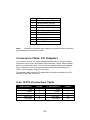
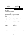
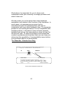
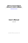
3DForce2 MX 3DForce2 MX - LCD nVIDIA TNT2 GeForce2 MX™/MX400™ User’s Manual Version 3.00 Copyright © 2000 Jaton Corporation, USA Contents INTRODUCTION ......................................................... 4 KEY FEATURES.......................................................... 5 SECOND GENERATION GPU ............................................ 5 PERFORMANCE ............................................................... 5 QUALITY ........................................................................ 6 HDTV/DVD PLAYBACK................................................... 6 SYSTEM REQUIREMENT ........................................... 7 CHECK LIST................................................................ 7 HARDWARE DESCRIPTION....................................... 8 HARDWARE INSTALLATION...................................... 9 INSTALLATION PROCEDURES............................................ 9 STEPS:........................................................................ 10 SOFTWARE INSTALLATION.................................... 11 ÿ MICROSOFT W INDOWS®9X.................................... 11 ÿ W INDOWS®ME DISPLAY DRIVER: ........................... 12 ÿ W INDOWS® 2000 DISPLAY DRIVER: ....................... 13 ÿ MICROSOFT NT™4.0 ............................................ 14 2 TECHNICAL ASSISTANCE ....................................... 15 FREQUENTLY ASKED QUESTIONS (FAQ)......................... 17 PINOUT AND SYNC FREQUENCIES........................ 19 ANALOG COLOR DISPLAY PINOUTS (DB 15) .................... 19 CONVERSION TABLE: PIN ADAPTERS .............................. 20 9-TO-15 PIN CONVERSION TABLE .................................. 20 TECHNICAL SUPPORT.................................................... 21 LIMITED WARRANTY. .............................................. 23 OTHER LIMITS. ............................................................. 23 EXCLUSIVE OBLIGATION. ............................................... 24 OTHER STATEMENTS. ................................................... 24 TERMS AND CONDITIONS. .............................................. 24 SERVICES AGREEMENT:................................................. 25 ENTIRE OBLIGATION. .................................................... 25 REDUCING WARRANTY CLAIM REJECTIONS........ 26 3 Introduction 3DForce2 MX / 3DForce2 MX-LCD(nVIDIA GeForce2 MX400™) is the first 3D graphics processor and multimedia controller that can drive dual digital displays. By incorporating GeForce2 MX’s break-through 3D architecture, in a 2-pipe form, GeForce2 MX delivers the full GeForce2 GTS 3D feature set at mainstream price points. GeForce2 MX’s integrated HDVP (High Definition Video Processor) can support 720p at the specified frame rates. When combined with a high performance, high-level software MPEG-2 decoder, and a Digital TV receiver, 3DForce2 MX / 3DForce2 MX-LCD delivers a cost-effective, high-quality HDTV solution. GeForce2 MX also enables ground-breaking new applications like HD timeshifting and digital VCR capabilities. 3DForce2 MX / 3DForce2 MX-LCD(GeForece2 MX400™) takes advantage of the latest advancements in PC computing to provide maximum performance in all graphics applications. It is the most complete Microsoft® DirectX® 7 hardware implementation and meets all the requirements specified by Microsoft PC 00, PC 99, and PC 99a initiatives. 3DForce2 MX / 3DForce2 MX-LCD(GeForce2 MX400™) delivers the industry’s fastest Direct3D® and OpenGL® acceleration in its class. GeForce2 MX ™ continues nVIDIA’s tradition of bringing leading edge technology to the mainstream with its costeffective, integrated VGA, 2D, 3D, and video in a single-chip solution. GeForce2 MX GPU delivers stunning visuals for a whole range of applications from crystal clear, high-resolution 2D/3D graphics on multiple displays to 3D games, to video applications such as HDTV, DVD and video conferencing. 4 Key Features Second Generation GPU • Twin View Architecture • Digital Vibrancy Control • Second generation transform and lighting (T&L) engine • Integrated Dual-Link TMDS transmitters • nVIDIA Shading Rasterizer (NSR) • High-Definition Video Processor (HDVP) • AGP 4x with fast writes • Double Data Rate (DDR) memory • 32-bit color, 32-bit Z/stencil buffer • 4 texels per clock • 256-bit graphics architecture • Cube environment mapping • DirectX and S3 texture compression performance • 700 million texel fill rate • 20 million triangles/sec through T&L and setup • 2.7 GB/sec memory bandwidth • 32 MB frame buffer size • Maximum 3D/2D resolution of 2048x1536@75Hz 5 • Complete DirectX® 7, DirectX® 6 and DirectX® 5 support Quality • nVIDIA Unified Driver Architecture • Industry’s first fully compliant professional OpenGL 1.2 support for all Linux™ and Windows® operating systems • WHQL-certified Windows 2000, Windows NT®4.0, Windows 98 and Windows NT®3.5 • Complete Linux drivers, including full OpenGL HDTV/DVD Playback • Optimized for multiple color depths including 32-bit: − High-Definition Video Processor (HDVP) for full-screen, full-frame video playback of 720p HDTV and DVD resolutions − Independent hardware color controls for video overlay − Hardware color space conversion (YUV 4:2:2 and 4:2:0) − 5-tap horizontal by 3-tap vertical filtering − 8:1 upscalling and downscalling − Per-pixel color keying − Multiple video windows with hardware color space conversion and filtering − DVD sub-picture alpha blended composting − Video acceleration for DirectShow, MPEG1, MPEG-2, and Indeo 6 System Requirement ± Intel Pentium® II or III, or compatible system with AGP Bus Extension Slot ± CD-ROM drive, Double speed or faster ± Hard Drive with at least 10MB Free space ± MS Windows® 9x / Me/NT™4.0/2000 operating system ± USB supplemental driver for mainboard’s core-logic chipset (Only for MS Windows® 95 OS) Check List R 3DForce2 MX, or 3DForce2 MX-LCD Multimedia Accelerator R Software & Documents CD R Quick Start Guide (Printed) 7 Hardware Description Plate PCB Layout & Specification 3DForce2 MX-LCD ONLY DVI Out n VIDIA GeForce2 MX400 Display Memory Y1 DB 15 VGA AGP BUS Product / PCB Reversion Chipset Memory Model / Size 3DForce2 MX 82118A nVIDIA GeForce2 MX/MX400 2M*32 SDRAMx4 32 MB 3DForce2 MX 82118D nVIDIA GeForce2 MX/MX400 2M*32 SDRAMx4 32 MB 3DForce2 MX-LCD 82118A nVIDIA GeForce2 MX/MX400 2M*32 SDRAMx4 32 MB RGB Monitor Connection 3DForce2 MX 15Pin RGB connector 32MB SDRAM/SGRAM AGP 4x RGB Out RGB Monitor 8 LCD Display Panel Connection 3DForce2 MX-LCD DVI Out Digital Video Interface 32MB Frame Buffer AGP 4x Hardware Installation Installation Procedures !! WARNING !! Discharge static electricity by touching the GROUND such as metal part of your case connected with good power ground before you handle the electronic circuit boards. 9 The manufacturer assumes no liability for any damage, caused directly or indirectly, by improper installation of any components by unauthorized service personnel. If you do not feel comfortable performing the installation, consult with a qualified computer technician. Steps: 1. Turn OFF all powers to your system, including any peripherals (printer, external drives, modem, etc.). 2. Disconnect the power cord and the monitor cable from the back of the computer. 3. Unfasten the cover mounting screws on your system and remove the system cover. Refer to your system user manual for instructions to determine the location of the mounting screws. 4. Remove the retaining screw that holds the slot cover in place. Slide the slot cover out and put the screw aside (you will need it to secure the adapter). 5. To install the adapter in AGP expansion slot, carefully line up the gold-fingered edge connector on the adapter directly above the expansion slot connector on the motherboard. Then press the adapter into place, completely. Use the (remaining) screw you removed to secure the adapter-retaining bracket in place. 6. Replace the computer cover. Secure the cover with the mounting screws you removed in Step 3. You have now completed the installation of your new graphics adapter on your system. < Very Important Note: For Windows®95 users, before you install the video display driver, you have to install USB supplemental driver for the mainboard’s PCI bridge functions. Otherwise, video driver installation won’t go through properly. Most mainboards’ CD that contained the USB supplemental driver, or logon their WEBsite for download. 10 Software Installation ÿ Microsoft Windows®9x New system installation: When the Microsoft Windows® PnP(Plug-and-Play) detected on the new hardware, click on [Cancel] button to allow the operating system starting with the VGA or SVGA driver. Do Not placed the 3DForce2 MX’CD into the CD ROM drive. After Windows®9x desktop loaded completely, following the video driver installation procedure below. 1. 2. 3. 4. 5. 6. 7. Insert the software’ CD into your CD-ROM drive (e.g. D: or E:). Autorun file pops up “Welcome” screen from software’ CD. Click on the “Display Driver” selection bar. Switch to “Settings” tab, then click on “ Advance” button. Tab on “Adapter” screen, if there is any. Click on “Change”, then “Have Disk”. Browse to “X:\MX\Win9x\Jatonagp.INF” (X is the letter of your CD-ROM drive; typically, D: or E:, etc.), and click OK. 8. The display device selected “3DForce2 MX series, nVIDIA GeForce2 MX”, then press on OK button. 9. Close and apply to finish AGP’s display driver installation. 10. Restart Windows to complete installation. 11 ÿ Windows®Me Display Driver: As with previous versions of Windows® 9x, the Windows®Me it also performs PnP when you added a new hardware, the <Add New Hardware Wizard> will pop-up for driver installation process. Click [Cancel] allow the system start with SVGA (Default from Microsoft Windows®) display driver. After the desktop loaded completely, placed the software CD into the CD ROM driver and proceed the display driver installation. 1. Autorun brings “Welcome Screen”, and select display driver to starting driver install. 2. On “Display property”, tab on “Settings” then click on <Advanced> button. 3. Tab on “ Adapter” screen, click on <Change>. 4. Check on “Specify the location of the driver (Advanced)”, and click <Next> button. 5. You have to specify a location such as “D:\MX\Win9x\” , or browser on the CD directories, then unfold on MX, unfold on Win9x. Click <Next> button to continue. 6. Wizard prompt a confirmation for device and a location of the driver file. Click <Next> button that will start copy file & updating hardware database in your operating system. 7. Then, press on <Finish> to complete. Upgrade system installation: Add or change your video adapter to an existing system, you may proceed a few steps before you install the new hardware and software(video display driver). The followings are some of the considers: 1. To change a new adapter, please remove the existing video driver, or replace it to SVGA driver 12 from Windows®9x/Windows®Me system before you remove the existing hardware. 2. To added a new adapter, make sure the mainboard that has available IRQ for new devices, and there is no conflict between the others. 3. If you try add this video adapter to ALL-IN-ONE mainboards (which video port built-in already), then you have to disable that port first. Otherwise, that will be a problem for the new video adapter setup. 4. The driver installation for upgrade system as same as above, if error occur when you proceed step 1,2 or 3, please consult with your system dealer or the existing hardware manufacturer support. ÿ Windows® 2000 Display Driver: Microsoft Windows®2000 detects this device and placed appropriate display driver from its operating system automatically, it doesn’t matter you have add a new or change the existing one. To maximum the video board acceleration and breadth its performance, you may install the manufacturer display driver as the followings: 1. 2. 3. 4. 5. 6. 7. Insert the software’ CD into your CD-ROM drive (e.g. X:). Autorun file pops up “Welcome screen” from software’ CD. Click on the “Display Driver” selection bar. Switch to “Settings” tab, then click on “ Advance” button. Tab on “Adapter” screen, if there is any. Click on “Change”, then “Have Disk”. Browse to “X:\MX\Win2k\Jatonagp.INF (X is the letter of your CD-ROM drive; typically, D: or E:, etc.), and click OK. 13 8. 9. The display device selected “3DForce2 MX series, nVIDIA GeForce2 MX”, then press on OK button. Close and apply to finish AGP’s display driver installation. ÿ Microsoft NT™4.0 To proceeding the video display driver installation, you may process the setup of service pack3 or above versions (Microsoft® Windows NT™4.0) first. 1. SELECT the “Display” icon in control panel and then SELECT the “Settings” page. 2. SELECT “Display Type...” button in the “Settings” page. 3. SELECT “Change...” button from the Adapter type section. 4. SELECT “Have Disk...” button from the Change Display page. 5. Microsoft Windows NT 4.0 will prompt you for the correct path where the video drivers are located. ENTER the path “X:\MX\Winnt4\” where X: is the CD ROM drive where the Software & Documents CD has been inserted. 6. If the driver “3DForce2 MX series, nVIDIA GeForce2 MX” is listed under the Display list, SELECT the “OK” button to continue. 7. Once the driver files are copied, RESTART Microsoft Windows NT 4.0 for the changes to take effect. 8. SELECT the desired color palette (the number of colors), desktop area (resolution), and refresh frequency in the settings page of Display Properties and then SELECT the “Test” button in the same page to determine whether your selection works properly. SELECT “Apply” to active the selected mode. 9. Re-start Windows if necessary. 14 Technical Assistance Q: Why is the display shifted or changed sizes when I switch display modes? Explain and Suggestion: Some monitors lack auto-sizing features or just do not synchronize properly to the video board output. In some cases, horizontal and vertical display adjustments may be necessary. Use the monitor control panel functions to adjust screen. In other cases, mode type and refresh rate adjustments may be necessary. Use the utility program, which provided by video card manufacturer or production developer. To centering the display with normal type (mode 3), and to reduce (decrease) the refresh rate with the monitor's specification. Q: What kind monitors can display 800x600 mode or higher resolution mode? Explain and Suggestion: To display 800x600 resolution at 60Hz refresh rate, the monitor must be capable of synchronizing a 31.5KHz horizontal scan rate (e.g., NEC 2A, 3D). At 72Hz refresh rate, the monitor must be capable of synchronizing a 48.0KHz scan rate (e.g., Sony HG 1304, NEC 4D, 5D, Seiko 1450). To display 1024x768 interlaced mode; the monitor must be capable of synchronizing a 35.5KHz horizontal scan rate (e.g., NEC 3D, Seiko 1430 or 1440). To display 1024x768 non-interlaced mode at 60Hz, the monitor must be capable of synchronizing a 48.7KHz scan rate (e.g., Sony HG 1304, NEC 4D, 5D, Seiko 1450). To display 1024x768 non-interlaced mode at 70Hz, the monitor must be capable of synchronizing a 56.4KHz scan rate (e.g., NEC 4D). Q: Windows screen won't come up, it kicks back to 15 DOS prompt. Why? Explain and Suggestion: Windows® 95 Inadvertently, certain configuration files (e.g., msdos.sys, and command.com) have been changed in the system. Proceed to correct that, is re-boot the system with a system (Windows® 95) formatted floppy diskette. There are many reasons to causing the system booting-up with unappropriated steps. Base on Microsoft support wizard on their WEBsite, there are many technical articles to help users with this subject, such as troubleshooting with VXD errors, virus, Fatal exceptions, etc., more details cover on each issue are descriptive and familiar with, and exclusively further to our support. Q: System hangs-up after installing video driver. Explain and Suggestion: Today, most video drivers are developed for 32-bit processing and may require a channel to Code/Decode. Conflict between device drivers and TSR (terminate-and-stay-resident) programs will inverted the display, and are particularly effectual at crashing computer. The most effective way to check for conflicts is to replace with the original video driver, or delete and re-install the current video driver to the system. Accomplishing IRQs (Interrupt Request Query) settings or troubleshooting the conflicts on hardware source may necessary. Most AGP video cards designed for Plug-n-Play, that means video card IRQ's setup which controls by main board’s (motherboard) circuitry and BIOS. Physically pulling out other devices from system, and re-starts the computer. Confirm and modify your IRQ addresses with qualified computer technician. Q: Multiple images or unreadable screen after loading video driver. Explain and Suggestion: There are a variety of reasons why the display might be distorted. One common reason is a monitor mis-match. Some older multifrequency monitors are unable to switch video modes without being turned off, then turned on again. If the problem occurring in windows, make sure that you have loaded that proper video driver, and that the driver is compatible with the monitor 16 being used. Try re-configuring your application software to use a compatible video mode. If problem persist in windows, load the standard generic VGA driver. The generic VGA driver should function properly with virtually every video board and VGA (or SVGA) monitor available. If that is an unsatisfactory solution, you may have to upgrade to a monitor that supports the desired video mode. Some new monitors are also synchronizing this problem because built-in DDC (Data-Digital-Channel) feature. Sometime that DDC automatically setup the display frequency without loading video driver. Try to turn it off, or change settings of monitor type in your system. Q: Selection of color, resolution and refresh rate combination that always backs to default after restart the system. Explain and Suggestion: Accordingly, there must be a bug (defected source-code) in video driver, or in the system. Debug the source-code or fix the error in video driver that should be done by the driver developer. Likewise, upgrade the video driver from the manufacturer or from the original software developer is necessary. Frequently Asked Questions (FAQ) Q1 Why do we need 3D graphics capability in our PC? Answer 3D technology is becoming increasingly important (and common) not only in games, but also in other applications such as VRML, which allows 3D scene descriptions in Web applications. 3D technology is used for image editing, modeling, and an increasing number of in home and business applications. In games, as well as other applications, 3D acceleration not only allows better visual qualities and more realistic scenery attributes than software alone, but it also allows a higher frame rate, which translates into a more interactive experience for the end user. Q2 What does “Rendering Engine” mean? Answer “Rendering Engine” generically applies to the part of the graphics engine that draws 3D primitives, usually triangles. In most implementations, the rendering engine is responsible for interpolation of edges and "filling in" the triangle. 17 Q3 What does the set-up engine do in a graphics controller? Answer A set-up engine allows drivers to pass triangles in the form of raw vertex information; whereas, most common designs force triangles to be preprocessed for the rendering engine in terms of delta values for edges, color, and texture. Q4 Why does a 3D graphics chip need to have both a rendering engine and a setup engine? Answer Any “3D application”, a game, VRML, or modeling package, can benefit from 3D rendering. This is especially true of an application that uses texturing extensively, because texturing and texture filtering are very intensive operations at the pixel level in terms of CPU operations and demands for memory bandwidth. Without a set-up engine in a graphics controller, the CPU has to calculate the delta values for edges, color, and textures; the drivers need to handle ten (10) times more extensive data. This results in slower 3D pipeline operations between the CPU and the graphics controller. Q5 If we use powerful CPUs, such as a Pentium™ 200, can a standard 2D graphics card achieve 3D performance? Answer Yes and no. Software rendering can take advantage of "tricks" learned by force of necessity through years of trial and error. With such stratagems, the speed of software rendering for simple scenes can approach that of low-level hardware 3D rendering. On the other hand, as scenes become more complex (or frame sizes become larger), there are conflicts between using the CPU for high-level game logic, geometry, lighting, and rendering, all of which increase their demands. No current CPU or system can perform advanced quality-enhancements (bilinear filtering and alpha blending) in real time. Even general case texture mapping with RGB lighting is too much for the current CPU generation. Q6 What does "software 3D" mean? Answer 18 Software 3D is generally used to mean using non-specific (2D) hardware in conjunction with the CPU to render for 3D applications. Some of these techniques allow usable 3D applications when high-powered and/or MMX™-equipped CPU's are employed along with special-case software optimization techniques. As stated above, SW 3D can achieve credible results with today's (software optimized) applications, but the rising popularity of good 3D hardware at the consumer price level is inexorably compelling the public to expect hardware level scene enhancements and frame rates. Q7 What is “SGRAM”? Answer Synchronous Graphics Random Access Memory (SGRAM) is a new and improved type of memory, custom-designed for graphics use. Q8 What is the advantage of as compared to ordinary DRAM? Answer is now capable of running at much higher speeds than Fast Page Mode or EDO DRAM. Also, is able to execute a small number of frequently executed operations, such as buffer clears, specific to graphics applications, independently of the controller. Pinout and Sync Frequencies Analog Color Display Pinouts (DB 15) PIN FUNCTION 1 Red Video1 2 Green Video1 3 Blue Video1 4 Not Used 19 5 Ground 6 Red Return (ground) 7 Green Return (ground) 8 Blue Return (ground) 9 Vcc (+5v DDC Power) 10 Sync Return (ground) 11 Monitor ID (not used) 12 SDA (DDC support) 13 Horizontal Sync 14 Vertical Sync 15 SCL (DDC support) Note: Analog monochrome type monitors use green video for all video input and ignore red and blue video. Conversion Table: Pin Adapters If you will be using a 9-to-15-pin adapter cable to link your 9-pin monitor connector to the 15-pin accelerator card connector, check Table carefully before you install the cable. The 9-to-15 pin adapter cables are available from a variety of sources, but they need to match the specifications in Table to work properly with your new card. The adapter cable requires a D-shaped 9 pin female connector and a Dshaped 15 pin male connector. 9-to-15 Pin Conversion Table 9 PIN SIGNALS PIN NO. 15 PIN SIGNALS PIN NO. Red 1 Red 1 Green 2 Green 2 Blue 3 Blue 3 Horz Sync 4 Horz Sync 13 Vert Sync 5 Vert Sync 14 20 Red Ground 6 Return Red 6 Green Ground 7 Return Green 7 Blue Ground 8 Return Blue 8 Sync Ground 9 Digital Ground 10 Ground 5 Analog Video Signals Black Level = 0 V Full Intensity (White) Level = +0.7 V Technical Support In the event you have a technical problem with this product, please read the README files in the software CD_ROM. Updated drivers are available through Jaton Web site. Have following information handy when you contact technical support: þ þ þ þ Name of the product. Software Driver and Version. System Information, such as CPU speed, BIOS version, Monitor Specification, etc. Description of the problems including any error messages. Telephone: (408) 934-9369 9-5 PST Mon. - Fri. FAX: (408) 942-6699 email: [email protected] Website: www.jaton.com NOTICE The information in this document is subject to change in order to improve reliability, design, or function without prior notice and does not represent a commitment on the 21 part of the company. In no event will the company be liable for direct, indirect, special, incidental, or consequential damages arising out of the use or the inability to use the product or documentation, even if advised of the possibility of such damages. No part of this manual may be reproduced or transmitted in any form or by any means without the prior written permission of the company. July 2000, Rev. A FCC SHIELDED CABLE WARNING: This equipment has been tested and found to comply with the limits for a Class B digital device, pursuant to Part 15 of the FCC Rules. Operation is subject to the following conditions: (1) this device may not cause harmful interference, and (2) this device must accept any interference received, including interference that may cause undesired operation, “SHIELD INTERFERENCE CABLE (S) MUST BE USED ACCORDING TO FCC 15.27©.” CAUTION: Changes or modifications not expressly approved by the Manufacturer could void your authority to operate this equipment in accordance with FCC rules and regulations. SOFTWARE LICENSE AGREEMENT: The Company grants the customer a non-exclusive, non-transferable license to use the software in this package for internal use on a single computer system. No other license of any kind is granted to any part of the product or any of the intellectual property therein. TRADEMARK AND COPYRIGHT: All Trademarks and Registered Trademarks belong to respective owners. 2000 Jaton Corporation. All rights reserved. 22 Limited Warranty. Manufacturer warrants that the products sold hereunder are free from defects in material and workmanship for a period of two (2) years from manufacturing date. This limited warranty applies only to the original purchaser of Jaton Product and is not transferable. This limited warranty does not apply if failure to the Product Registration, or over thirty (30) days from purchase (original invoice date). This Limited Warranty does not cover any incompatibilities due to the user’s computer, hardware, software or any related system configuration in which the Jaton Products interfaces. Proof of purchase will be requiring before any consideration by Manufacturer occurs. Other Limits. The forgoing is in lieu of all other warranties, expressed or implied. Including but not limited to the implied warranties of merchantability and fitness for a particular purpose. Manufacturer does not warrant against damages or defects arising out of improper or abnormal use of handling of the products; against defects or damages arising from improper installation (where installation is by persons other than Manufacturer), against defects in products or components not manufactured or installed by Manufacturer, or against damages result from nonmanufacturer made products or components. This warranty does not apply if the Product has been damaged by accident, abuse, nor misuse. This warranty also does not apply to products upon which repairs have been affected or attempted by persons other than pursuant to written authorization by Manufacturer. 23 Exclusive Obligation. This warranty is exclusive. The sole and exclusive obligation of Manufacturer shall repair or replace the defective products in the manner and for the period provided above. Manufacturer shall not have any other obligation with respect to the Products or any part thereof, whether based on contract, tort, and strict liability or otherwise. Under no circumstances, whether based on this Limited Warranty or otherwise, Manufacturer shall not be liable for incidental, special, or consequential damage. Other Statements. Manufacturer’s employees or representatives’ ORAL OR OTHER WRITTEN STATEMENTS DO NOT CONSTITUE WARRANTIES, shall not be relied upon by Buyer, and are not a part of the contract for sale or this Limited Warranty. Terms and Conditions. Direct Jaton Customer: This warranty applies only for a period of two (2) years from purchase date of Jaton original invoice. Reseller/ Vendor: This warranty applies only for a period of two (2) years from manufacturing date. Registered User: This warranty applies only for a period of two (2) years from purchase date and register within 30 days of purchase date from legal reseller. 24 Others: If the products do not conform to this Limited Warranty (as herein above described), Manufacturer should charge services such as repair, replacement whether based on its costs. Shipping and installation of the replacement Products or replacement parts shall be at User’s expanse. Services agreement: (1) All applicants shall completed service request form from Manufacturer. (2) All returned checks will be charged a $20.00 fee by Manufacturer. (3) All repair and replacement services allow 4-6 weeks from the date of receiving by Manufacturer. (4) All products without warranties require service processing fee $20 (payment in advance), which is not refundable. Entire Obligation. This Limited Warranty states the entire obligation of Manufacturer with respect to the Products. If any part of this Limited Warranty is determined to be void or illegal, the remainder shall remain in force and effect. Some 25 states do not allow limitation of implied warranties, or exclusive or limitation on product incidental or consequential damages, so above limitation may not apply to you. This warranty gives you specific legal rights. You may have other rights, which may vary from state to state. This warranty applies only to this product, and is governed by the law of the State of California. Reducing Warranty Claim Rejections. To reduce the potential of incurring damages not covered by Manufacturers warranties, we strongly recommend the following: • Read your manuals before installing peripherals and/or before making changes to the machine’s configuration; • Ask your dealer if there are any known problems with the system requirements or installation procedures for any add-on products that your are purchasing; • Buy industry standard products where compatibility issue are more likely to surface; • If you are unsure about installation for a new product, contact your dealer’s service department. 26 We believe it is important for you to know and understand what your warranty coverage provides and what it does not. We also want you to be aware that most hardware warranties only relate to the function of the hardware. In most cases, no assurances are given by the manufacturer that the hardware item will work in conjunction with any other hardware item. If a computer product is not working because it is not compatible with another product, or because it has not been properly installed and set-up, the manufacturer does not pay for the service time. To help avoid these inconveniences, contact a professional consultant that one can help you determine the possibility of incompatibility issue before you purchase add-on or accessories. For Reseller / Vendor Use Only Serial Number - ten or eleven digit code, the serial number consists of the following parts: Packaging Type Manufactured Date Code A 99 5 Production Numerical Code 000015 Year Month XXXXX-XXXXX S/N: A995000015 123456789123456789123456789123456789abcdefghijklmnop XXXXX 00.0 XXXX XX XXXXXXXX Product Label and Manufactured Date Code 27