1
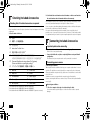
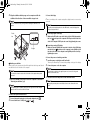
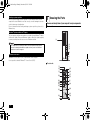
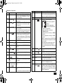
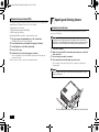
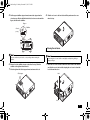
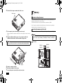
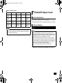
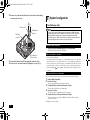
NEC_Mate.fm Page 1 Monday, November 12, 2012 3:39 PM User's Guide MB Model This User's Guide has been written mainly with the information specific to this computer, assuming that the user is able to perform basic Windows operation and understands how to use help in its installed applications to resolve problems. In this user's manual, unless specified, "Windows 7" refers to Windows® 7 Professional 32 bit with Service Pack 1 (SP1) installed. System configuration and software installation should be conducted by a user who has administrator privileges. If a [User Account Control] screen comes up, please be sure to confirm the contents before continuing. The information contained within this manual applies to the following models: • MB Model: MC32M/B-F, MC33L/B-F, MG32M/B-F, MG33L/B-F 1 Checking Included Accessories .............................................2 8 Memory ............................................................................... 12 2 Connecting Included Accessories ..........................................2 9 PCI board/PCI Express x1 board ........................................ 13 3 Windows Setup ......................................................................4 10 System Configuration .......................................................... 14 4 Knowing the Parts ..................................................................6 11 Security Chip Function ........................................................ 15 1 5 Mouse.....................................................................................8 12 Applications ......................................................................... 16 6 LAN Function..........................................................................9 13 Recovery ............................................................................. 17 7 Opening and Closing Covers ...............................................10 Appendix ............................................................................. 19 Note: The illustrations, screenshots, icons, and on-screen text shown in this document may differ from the ones you actually encounter. NEC_Mate.fm Page 2 Monday, November 12, 2012 3:39 PM 1 Checking Included Accessories Checking that all included accessories are present Please open up the box and check that all included items and accessories are there. Please immediately contact the place of purchase if any items happen to be missing or damaged. 1. Check contents of the box. 保修书 修理サ−ビス保証規定書 *3 安全使用说明 Instructions For Safe Use *2 安全にお使いいただくために *3 NEC软件的使用条件 【即EULA】(对顾客的特别提示) (请务必先仔细阅读如下内容后,决定是否打开本个人电脑的包装)*1 Terms and Conditions for using software (For Customer) (Please read this before opening the package) *2 2 Important points when connecting ソフトウェアのご使用条件(お客様へのお願い) *3 Base unit Power cord Keyboard Mouse Two stabilizers Cable stopper Screw (×1) Application Disc User's Guide Recovery Disc Connecting Included Accessories *1 *2*3 *1 : Included with model MC32M/B-F and model MC33L/B-F *2 : Included with model MG32M/B-F and model MG33L/B-F *3 : Included with model MG32M/B-F and model MG33L/B-F (Japanese versions) 2 If they happen to differ, please contact the place of purchase immediately. Please also keep your written warranty in a safe place for future reference. If your encounter a breakdown during the warranty period, we shall provide repairs based on the conditions specified in the warranty. For repairs after the warranty period has expired, please consult the place of purchase or one of our specified customer service locations. If it is deemed possible to regain functionality, we are able to perform paid repairs at the customer's request. *1 2. Confirm that the model number and serial number on the base unit matches the model number and serial number written on the warranty. • Do not touch connector terminals when connecting any items. Failure to do so may cause damage. • Connect the LAN cable, only after completing Windows setup and firewall configuration. This ensures that your computer can be safely connected to a network. Connecting power sources 1. Attaching the stabilizers This computer includes stabilizers that keep your computer stable when it is stood vertically. The stabilizers are not attached to the computer at the time of shipment. When you stand the computer vertically, attach one or two stabilizers to ensure that it will not fall over. Stabilizers are not necessary when the computer is placed horizontally. If you are not using the stabilizers, continue to step 2 "Connect the keyboard and the mouse" (p.3). Attaching two stabilizers 1 Place the computer at the edge of a desk and keep it stable. It is recommended to put thick paper or cloth on the desk or table to prevent damage. NEC_Mate.fm Page 3 Monday, November 12, 2012 3:39 PM 2 Align the stabilizers with the prongs on the computer and slide the stabilizers in the direction of the arrow until the stopper locks. 3. Connect the display Connect your display to the computer using either a digital connector or an analog connector. Please be careful not to hurt your fingers when attaching the stabilizers to the computer. If you will use the dual display function on the MB model, connect the display after Windows Setup has finished. Connecting a digital LCD display 1 Make sure the DVI cable connected to the back of the LCD display matches the icon ( ) and shape of the computer's DVI-D port, and then attach the cable to the computer's DVI-D port and secure it by tightening the screws. Overhead view Plastic feet Connecting an analog LCD display 1 Make sure the analog RGB cable connected to the back of the LCD display matches the icon ( ) and shape of the computer's analog RGB port, and then attach the cable to the computer's analog RGB port and secure it by tightening the screws. Stopper 4. Connect the power cord and the ground wire Prong Attaching one stabilizer When you place the computer vertically with the right front side facing a wall, attach one stabilizer to the left front side of the computer. 1 Insert the power cord plug into an AC wall outlet. There may be different ways of connection depending on the type of the display. 2 Connect the power cord to the computer. If a ground wire is attached to the supplied power cord, connect it to the ground terminal of the AC wall outlet. Do not block the air vent located on the left front side of the computer when placed near a wall. 3 1 Attach one stabilizer to the left front side of the computer as described in "Attaching two stabilizers" (p.2) Insert the other end of the power cord into an AC wall outlet. Although the power may turn on and off after a few seconds, the machine is not broken. When attaching only one stabilizer, please place the opposite side of the computer against the wall to ensure that it will not fall down. 2. Connect the keyboard and the mouse 1 2 Connect the purple keyboard port to the purple keyboard port ( Connect the mouse to a USB port ( or ). ). 3 NEC_Mate.fm Page 4 Monday, November 12, 2012 3:39 PM 3 Windows Setup When you first power up your new computer, it is necessary to perform Windows setup. Turning on the power 1 2 Important points during setup • Always follow the procedure written in the manual. Setup may not be able to be successfully completed if you omit any steps, press any keys other than the ones indicated on the screen, or operate any switches. • Do not connect any external peripherals. Never connect any peripherals (printers, memory, etc.) other than the items outlined in " 2 Connecting Included Accessories" (p.2). Please connect or install such peripherals after " 3 Windows Setup" had been completed. • Do not connect a LAN cable. To ensure safe network connection, only connect a LAN cable after Windows setup and firewall configuration has been completed. • Do not turn off the power during setup. The setup program is running normally even if the screen appears to stop. Please keep following the steps in the manual. • Do not leave the computer alone during setup. Do not leave the computer unattended until Windows setup has completed including passing all the screens which require your key operations, and power OFF. ). Setup Procedure Start Windows 7 setup. • It will take some time for the [Windows 7 Professional] screen to appear. Please wait for a while. • During setup, some parts of the screen may turn black. However, this does not necessarily mean that there is a problem. • Please contact your system administrator for the appropriate settings in steps 1 to 3, 6 and 7. 1 Once the [Windows 7 Professional] screen appears, set [Country or region], [Time and currency] and [Keyboard layout], and then click [Next]. 2 Enter your user name and computer name when prompted and click [Next] to continue. During Windows setup, you are required to enter the name of the person who will be using the computer (user name), as well as the computer name. Please choose these names in advance. 4 Press the power switch ( Never turn off the power during Windows setup. Turning off the power switch or pulling out the power cord in the middle of this process may lead to damage. If there is some sort of problem or you accidentally press the power switch, please see "If you encounter problems during setup" (p.5). Preparation for setup For the user name and computer name, use single-byte alphanumeric characters only (20 or less). If the following symbols or if certain strings are used for any part of the user name or computer name, Windows setup may not be completed and some applications may not run correctly. • Double-byte characters, single-byte Kana characters, non-standard characters, all symbols, spaces • Restricted strings CON, PRN, AUX, CLOCK$, NUL, COM1-COM9, LPT1-LPT9, NONE Turn on the display. Setup cannot progress to the next step unless you enter a valid user name and computer name. 3 4 Enter a user account password when prompted and click [Next] to continue. 5 After checking the contents, check [I accept the license terms] and click [Next] to continue. Please check the contents when the [Please read the license terms] page is displayed. If you do not accept the license terms, setup cannot continue. NEC_Mate.fm Page 5 Monday, November 12, 2012 3:39 PM 6 When the [Help protect your computer and improve Windows automatically] page is displayed, please select either [Use recommended settings], [Install important updates only], or [Ask me later]. 7 When the [Review your time and date settings] message appears, set [Time zone], [Date], and [Time], and then click [Next]. The screen should change several times during this process, and it may take some time before the desktop is displayed. 8 9 10 When the [Shut down your computer] dialog is displayed, click [OK]. 11 Turn off the display Click [Start]. Click [Shut down]. The computer power will then turn off. After Windows setup has completed, Windows Experience Index measurements are performed once your computer continues to be in an idle state for around 15 minutes. While these measurements are in progress, the power plan will change to [High performance]. At this time, you may notice the power to the display cutting out. If you encounter problems during setup If you accidentally turn off the power during setup The setup process will not be successfully completed and Windows system files or the registry may be corrupted. In this case, either perform Windows recovery or consult your place of purchase. The computer is unresponsive or shows an error message during setup Make a note of the error message and hold down the power switch for at least four seconds to perform a forced shutdown. Please wait for at least five seconds before turning the power switch back on. After that, please see the above "If you accidentally turn off the power during setup". Using and configuring your computer after setup is complete Creating multiple hard disk partitions As a default setting, the first internal hard disk has only one useable partition (volume), designated as the C: drive. However, it is possible to divide the C: drive into multiple partitions. Please refer to the following steps if you would like to change the factory default settings and reduce the size of the C: drive in order to create a new partition from the resulting unassigned space. 1 2 3 4 Go to [Start] and then open [Control Panel]. 5 6 7 Select the volume marked as (C:) and right click it. Click [System and Security] and then [Administrative Tools]. Double click [Computer Management]. On the tree displayed on the left side of the window, click [Storage] [Disk Management]. Click [Shrink Volume]. Enter the desired size into the [Enter the amount of space to shrink in MB:] box. The size entered here will become the maximum size of the newly created partition. Click [Shrink]. 8 9 After shrinking is complete, select the unassigned space that has been reserved, and right click it. 10 11 12 Click [New Simple Volume]. 13 14 Confirm that [Assign the following drive letter:] is selected and click [Next]. 15 Click [Finish]. Click [Next]. Enter the desired volume size into the [Simple volume size in MB:] box and click [Next]. Confirm that [Format this volume with the following settings:] is selected and click [Next]. • Do not select [Mark Partition as Active] for the newly created partition. • It is not possible to shrink the [Recovery Partition]. • It is possible to change the drive letter if necessary. • Depending on the system environment, there may be some cases where [Shrink Volume] is not possible. For more information about [Shrink Volume], please refer to [Shrink a Basic Volume] in the [Computer Management] help file. Disk management usage instructions [Disk Management] help. 5 NEC_Mate.fm Page 6 Monday, November 12, 2012 3:39 PM Creating a system repair disc We recommend creating a system repair disc for times when problems such as corrupted files cause Windows to not load correctly, even after running in safe mode or the last known good configuration. For more information about creating and using a system repair disc, please refer to Windows help. 4 Knowing the Parts Names and descriptions of your computer's major components The front side Windows® Update and Microsoft® Update The latest updates and important updates are available through Windows® Update or Microsoft® Update. Please run Windows® Update or Microsoft® Update regularly to ensure you always have the latest version of Windows installed. (1) (2) (3) (4) Your computer has been delivered to with the all current updates already installed. Please do not attempt to uninstall these updates as it may cause issues that have already been resolved to reappear. (5) Windows Service Pack (6) "Windows® 7 Service Pack 1 (SP1)" is pre-installed on this computer. It is not possible to uninstall "Windows® 7 Service Pack 1(SP1)". The back side (7) (8) (5) (19) (15) (16) (17) (23) (10) (11) (12) (13) (9) (18) (20) (21) (22) (14) 6 (16) NEC_Mate.fm Page 7 Monday, November 12, 2012 3:39 PM Explanation of Components Number Name (1) Optical drive (2) Power switch ( (3) Power LED ( ) ) (4) Drive activity LED ( ) (5) USB port ( (6) (7) Stabilizer (8) PS/2 mouse port ( ) PS/2 keyboard port ( (9) (10) (11) ) ) Explanation This computer features either a built-in DVD Super Multi drive or a built-in DVD-ROM drive. The type of drive varies by model. This is used to turn the computer on/off or change the power state. It indicates the power status. This indicator lights up when the power is on and when the computer is in Sleep mode. This indicator lights when accessing the hard disk and the optical drive. Do not press the power switch when the Drive activity LED is lit. It may cause damage to the hard disk. This port can be used to connect to USB devices. This USB port supports both USB 2.0 and USB 1.1. In order to take advantage of USB 2.0 transfer speeds, it is necessary to be connected to a USB 2.0 enabled device. This keeps the computer stable. A port used to connect a PS/2 (MiniDIN 6-Pin) mouse. A port used to connect a PS/2 (MiniDIN 6-Pin) keyboard. This is used to connect to devices that have a serial port. Analog RGB port ( ) A port used to connect an analog interface display. Line input terminal (mini A terminal used to input audio signals from audio devices. jack) ( ) Serial port ( ) Number Name (15) Cable stopper (16) (17) Explanation Prevents the keyboard cable from pulling out or protects devices connected using cables against theft. The cable stopper can be found in the included accessory case. Fixes the roof cover firmly. A port used to connect a LAN cable. Slide stopper LAN port ( ) Communication speed LED LAN port (18) Chassis lock ( (19) (20) DVI-D port ( ) PCI Express x1 slot ) (21) PCI slot (12) Mic terminal (mini jack) A terminal used to connect microphones and input audio signals. ( ) (22) AC power input jack (13) Headphone/line out shared output terminal (23) USB port (supports USB 3.0) ( ) (14) (mini jack) ( Air vent A terminal used to output audio signals to audio devices. ) These holes are designed to allow internal heat to escape. Please be careful not to leave the air vent blocked. Network communication/ Connection LED (ACT/LINK) • Communication speed LED - Lights orange when connecting to a 1000 Mbps network. - Lights green when connecting to a 100 Mbps network. - Does not light when connecting to a 10 Mbps network. • Network communication/Connection LED (ACT/LINK) Flashes when data is being read from or written to the network. Also lights when receiving link pulses from a hub or switch. However, the data may not necessarily be being read from or written to this computer. A security cable (sold separately) can be attached to this slot. A port used to connect a DVI-D interface display. A slot used to attach a PCI Express x1 board. Helps to enhance and extend the machine's functions. A slot used to attach a PCI board. Helps to enhance and extend the machine's functions. A jack used to supply power to the machine. Connects to the supplied power cord. This port can be used to connect to USB devices. This USB port supports USB 3.0, USB 2.0, and USB 1.1. In order to take advantage of USB 3.0 transfer speeds, it is necessary to be connected to a USB 3.0 enabled device. 7 NEC_Mate.fm Page 8 Monday, November 12, 2012 3:39 PM Status LEDs 5 Base unit A USB mouse is included. Power LED LED state On (Green) On (Orange) Off Computer State Computer power on Sleep Computer power off, or hibernating Drive activity LED LED state On (Green) Off Mouse Computer State The hard disk or optical drive is currently accessing data. The hard disk or optical drive is not currently accessing data. A sensor detects the movement of the mouse with the assistance of the light source at the bottom of the mouse. In the following cases the mouse may not move properly (the mouse pointer may respond as you expect). • Reflective surfaces (mirrors or glass) • Surfaces with continuous patterns like halftone printings (such as magazines and images in newspapers) • Striped surfaces or patterns with strong shading • Shiny surfaces including transparent and translucent materials Using the scroll wheel Keyboard Caps lock indicator LED LED state On (Green) Off Computer State <Caps Lock> is on (all letters are entered as capital letters) <Caps Lock> is off (all letters are entered as lowercase letters) Scroll Lock indicator LED LED state On (Green) Off Computer State <Scr Lock> is on <Scr Lock> is off Num Lock indicator LED LED state On (Green) Off 8 Computer State <Num Lock> is on <Num Lock> is off Scroll wheel features are only available when using the applications that support them. • Vertical scrolling You can scroll up and down by rotating the wheel back and forth. • Auto scrolling A scroll icon is displayed when you click or hold down the wheel. When the icon is displayed, you can scroll up and down by moving the mouse in the direction of the arrows. By clicking the wheel again or realizing your finger, the scroll icon disappears. NEC_Mate.fm Page 9 Monday, November 19, 2012 3:24 PM 6 LAN Function • In order to enable WoL, it is necessary to install special software on the administrator's PC to allow sending of Magic Packets. • It is not possible to use WoL in cases where the previous system shutdown (power off, sleep, or hibernate) was not correctly completed. If this is the case, please turn the power back on, restart Windows, and once again perform a system shutdown using the correct procedure. • WoL cannot be used with a hub that only supports a speed of 1000 Mbps. Please use a hub that supports 10M/100M/1000M Auto-negotiation. This section covers important points and the correct procedure for setting up the LAN (Local Area Network) function. LAN settings The following provides a simple explanation about how to perform network setup in order to connect to a LAN. Setting up a network connection Network connection settings can be changed by going to the [Control Panel] and clicking [Network and Internet] [View network status and tasks] [Change adapter settings]. For more detailed information, please refer to Windows help. How to configure your computer to allow WoL from when the power is turned off The following steps can be used to configure your computer to allow WoL from when the power is turned off. 1 Turn on the power and immediately press <F2> several times. The BIOS setup utility will then be displayed. 2 In the [Advanced] menu, select [Power Management Setup] and press <Enter>. 3 4 5 Set [Resume On LAN] to [Enabled]. The following step allows you to change settings such as the computer name. Setting the computer name and network to connect to You can change settings related to the connected network and change the name of your computer as it is displayed on the network by opening the [Control Panel] and clicking [System and Security] [System], and then selecting [Change settings] under [Computer name, domain, and workgroup settings]. For more detailed information, please refer to Windows help. This is all you need to do to correctly setup your LAN. Remote power on (WoL - Wake on LAN) Remote Power On (WoL - Wake on LAN) allows you to do the following. • Remotely turn your computer on after the power is off. • Remotely wake up your computer after sleep or hibernate. Press the <F10> key. Confirm that [Yes] is selected and then press <Enter>. These setting values are saved, the BIOS setup utility will finish, and your computer will restart. Configuration is now complete. How to configure your computer to allow WoL from sleep or hibernate mode These settings can be found in [Device Manager] [Network adapters]. For more detailed information, please refer to Windows help. If you configure your computer to allow WoL, the LAN adapter stays active, even when the computer power is off. A special packet (Magic Packet) that instructs your computer to turn on can be transmitted from a remote administrator's PC. When this packet is received by the computer's dedicated controller, it triggers the power to be turned on. This allows you to be able to remotely turn your computer's power on or wake it up from sleep or hibernate from an administrator's PC when your computer has a LAN connection. 9 NEC_Mate.fm Page 10 Monday, November 12, 2012 3:39 PM Network booting function (PXE) 7 This enables booting via a network, and remote connection to your computer from an administrator's PC which allows you to do the following. • Operating system installation • BIOS flashing (Rewriting the BIOS ROM) • BIOS configuration changes Opening and Closing Covers Removing the roof cover The roof cover needs to be removed when installing internal devices such as memory or a PCI board. Configuring the BIOS setup utility to enable network booting. 1 Turn on the power and immediately press <F2> several times. The BIOS setup utility will then be displayed. 2 3 4 5 In the [Advanced] menu, set [Network Boot Agent] to [Enabled]. In the [Boot] menu, set [1st Boot] to [Network]. Press the <F10> key. Confirm that [Yes] is selected and then press <Enter>. These setting values are saved, the BIOS setup utility will finish, and your computer will restart. This is all you need to do to correctly setup network booting. The plate turns very hot right after the use of the machine. Please do not touch to prevent burns. It is recommended to wait 30 minutes after the computer is turned off and the power cord is disconnected before installing or removing internal devices. 1 2 Turn off the computer. 3 4 If you are using a security lock, remove it. Make sure the power LED is off and then remove the power cord and all cables and cords. If the computer is placed horizontally, proceed to step 7. If the computer is placed vertically, place the computer as shown in the following figure. Place the computer at the edge of a desk when removing the stabilizers to prevent damage to the machine. Stabilizer Place the computer at the edge of the stabilizer desk and keep it stable 10 NEC_Mate.fm Page 11 Monday, November 12, 2012 3:39 PM 5 Pull the upper stabilizer stopper forward, remove the stopper from the chassis prong, slide the stabilizer in the direction of arrow as shown in the figure, and remove the stabilizer. 8 Slide the roof cover to the front side and lift up and remove the cover where it stops. Stopper Chassis prong Stabilizer Closing the roof cover Refer to the following procedure when closing the roof cover. Please be careful not to pinch, strike, or cut your fingers when removing the stabilizers. 6 Release the other stabilizer stopper as described in step 5, slide the stabilizer to the right and then remove it. 7 Slide the right and left slide stoppers inward and remove the lock. Slide stopper When closing the roof cover, hold the cover tightly to avoid pinching, striking, or cutting your fingers. 1 Attach the roof cover at about 40 mm above the back side of the machine and slide the cover to the back side, keeping the roof cover hook and the hole of the machine close. Hook Hole 11 NEC_Mate.fm Page 12 Monday, November 12, 2012 3:39 PM 2 Slide the slider stoppers outward and lock the cover. Slide stopper 8 Memory Before installing the board Before installing memory in this computer, check the memory compatibility, the installation order and the location of the slot. This machine has four memory slots and allows a maximum of 8 GB. Up to four memory cards can be installed one at a time (two memory cards are installed at the time of shipment from the factory). Inserting the memory into the slot 3 If the computer is placed horizontally, proceed to step 6. Insert the memory in the order of DIMM_A2, DIMM_B2, DIMM_A1 and DIMM_B1. When you stand the computer vertically, place at the edge of the desk to keep it stable. 4 Align the stabilizers with the prongs on the computer and slide the stabilizers in the direction of the arrow until the stopper locks. To use dual-channel memory access with two pairs of memory cards, install the two pairs of the same capacity in DIMM_A2 and DIMM_B2 or DIMM_A1 and DIMM_B1. Slot location Please be careful not to pinch, strike, or cut your fingers when attaching stabilizers. Prong Stopper 5 6 7 Stand the computer vertically. Attach the security lock, if necessary. Connect the power cord and all other cables and cords. 12 DIMM_A2 DIMM_B1 DIMM_A1 DIMM_B2 NEC_Mate.fm Page 13 Monday, November 12, 2012 3:39 PM Memory combination examples Total size 2 GB (2,048 MB) 4 GB (4,096 MB) 8 GB (8,192 MB) 8 GB (8,192 MB) DIMM_A1 — — 2 GB (2,048 MB) — DIMM_A2 2 GB (2,048 MB) 2 GB (2,048 MB) 2 GB (2,048 MB) 4 GB (4,096 MB) DIMM_B1 — — 2 GB (2,048 MB) 2 GB (2,048 MB) 4 GB (4,096 MB) 2 GB (2,048 MB) — 9 DIMM_B2 — PCI board/PCI Express x1 board Before installing the board The following are the available board sizes for this computer. • PCI board: half height (Low Profile), no larger than 64.5 (W) mm × 167.7 (D) mm • PCI Express x1 board: Low Profile, no larger than 68.9 (W) mm × 167.7 (D) mm Installing and Removing Installing The maximum size of the memory is 8 GB, but not all sectors can be used as there needs to be some available space for PCI devices. Windows 7 Professional 32 bit allows a maximum of 4 GB of memory. • The PCI board/PCI Express x1 board (PCI board) is very vulnerable to static electricity. Touching the PCI board when static electricity is generated in your body may damage the board. Before touching the board, eliminate static electricity by touching a metal object such as an aluminum sash or door knob. • Do not touch the PCI board port. This may cause poor connections or damage. • Please be careful not to touch the parts on the board or the solder-mounted areas. • Forcefully inserting the PCI board in the wrong direction may cause damage to the connector port of the computer and the PCI slot/PCI Express slot x1 (PCI slot). • Make sure your PCI board is compatible with this computer. • Do not touch any other internal parts or switches inside the machine. 1 Open the roof cover as described in "Removing the roof cover" (p.10). 13 NEC_Mate.fm Page 14 Monday, November 12, 2012 3:39 PM 2 Remove one screw from the PCI board slot cover that you are installing, and remove the slot cover. 10 System Configuration The BIOS setup utility PCI slot cover PCI Express x1 Slot cover Do not turn your computer off with the power switch while in the BIOS setup utility. When turning the power off after configuration is complete, be sure to either exit the BIOS setup utility and shutdown your computer from the Windows menu after Windows has loaded, or turn the power off after selecting [Save Changes and Power Off] from the [Exit] menu when you wish to save the new settings. PCI board connector Entering the BIOS setup utility 1 PCI Express x1 Slot connector 3 4 Secure the PCI board to the PCI slot using the screw from step 2. Close the roof cover as described in "Closing the roof cover" (p.11). Turn on the power and immediately press <F2> several times. The BIOS setup utility will then be displayed. BIOS setup utility basic operation • You can use the keyboard. • Select the menu bar cursor using <> <> and settings using <> <>. Open the pop menu using <+> <-> or <Enter> and use <> <> to change the setting values. • You can move the cursor in the settings (e.g., Hour/Minute/Second of the system time) using <Tab> or <Enter>. Use the numeric keys to enter the date and time. • For the settings with , press <Enter> to display the sub-menu and press <Esc> to return. Restoring default factory setting values Please follow these steps to restore your system to the default factory settings. 1 2 3 4 5 Enter the BIOS setup utility. Press the <F9> key. The message [Load Optimized Defaults?] appears. Confirm that [Yes] is selected and then press <Enter>. This will load the default factory setting values. Press the <F10> key. The message [Save configuration and reset?] appears. Confirm that [Yes] is selected and then press <Enter>. These setting values are saved, the BIOS setup utility will finish, and your computer will restart. Configuration is now complete. 14 NEC_Mate.fm Page 15 Monday, November 12, 2012 3:39 PM 11 Security Chip Function The security chip is now initialized. To use the security chip again, enable it by following the procedure in "Enable the security chip". Enable the security chip Outline After initializing the security chip, carry out the following procedure to enable it for use again. • The security chip function is only enabled for models MG32M/B-F and MG33L/B-F. • The security chip does not guarantee complete protection of data or hardware. Always exercise appropriate caution when managing and handling important data. • In addition to the security chip function, we recommend configuring supervisor and user passwords to the BIOS setup utility. • When performing computer recovery, reinstalling the operating system, or using a separately sold operating system, initialize the security chip before enabling it. Refer to "Before sending your computer for repair" for the procedure to initialize the security chip. Before sending your computer for repair When you send your computer for repair, please be sure to cancel supervisor and user password settings for the BIOS setup utility and initialize the security chip to prevent the divulging of information. Please refer to the following procedures for security chip initialization. 1 Turn the power on and immediately press <F2> several times. The BIOS setup utility will then be displayed. 2 In the [Security] menu, select [Security Chip Configuration] and press <Enter>. 3 Confirm that [Current TPM State] is set to [Enabled&Activated]. If [Current TPM State] is not set to [Enabled&Activated], please enable the security chip referring to "Enable the security chip" on , and then initialize the security chip. 4 5 Set [Change TPM State] to [Clear]. 6 Select [Yes] and then press <Enter>. The settings are saved and the BIOS setup utility exits. 7 If a confirmation screen is displayed after the computer restarts, press <Shift> + <F10>. The settings are saved and the computer restarts. 1 Turn the power on and immediately press <F2> several times. The BIOS setup utility will then be displayed. 2 In the [Security] menu, select [Security Chip Configuration] and press <Enter>. 3 Confirm that [TPM Support] is set to [Enabled]. If it is set to [Disabled], please change it to [Enabled]. 4 5 Set [Change TPM State] to [Enable&Activate]. 6 Select [Yes] and then press <Enter>. The settings are saved and the BIOS setup utility exits. Press the <F10> key. A confirmation message is displayed. 7 If a confirmation screen is displayed after the computer restarts, press <F10>. The settings are saved and the computer restarts. The features of the security chip are now enabled. You can reset security chip feature settings by setting [Change TPM State] to [Clear]. Therefore, we recommend you set up a supervisor password/user password before you use security chip features so that a higher level of security can prevent a third party from resetting security chip feature settings. Press the <F10> key. A confirmation message is displayed. 15 NEC_Mate.fm Page 16 Monday, November 12, 2012 3:39 PM 12 Applications Microsoft® Office trial Deleting Data from the Hard Disk The Recovery Disc is not included with model MC32M/B-F and model MC33L/B-F. About Deleting Data from the Hard Disk Microsoft® Office trial is not pre-installed in the Japanese version of model MG32M/B-F and model MG33L/B-F. "Microsoft® Office trial" is installed on this computer. To use Microsoft® Office, you need to purchase a product key separately. "Microsoft® Office trial" is installed only at the time of shipment from the factory. If you perform a recovery, it will no longer be installed. If you wish to use Microsoft® Office, purchase it from the Microsoft® website. Data can be deleted from the computer's hard disk. Data written to the hard disk can be removed using the [Recycle Bin] or by formatting the computer to the original state. Selecting this menu will remove hard disk data that cannot be removed by hard disk formatting of operation system standard, and the removed data will not be easily recovered with recovery tools. Format the hard disk before transferring or disposing of the computer. Before deleting the hard disk data, return the BIOS Setup Utility setting to the factory setting values. Data can be deleted from the computer in the following 3 ways. • Simple mode (1 time erasure) Overwrites "00" data entirely from the hard disk once. • NSA-introduced mode (3 times erasure) Deletes data from the hard disk in a method compliant to the U.S. Department of Defense NSA Standard. The data is deleted effectively by writing random data 1, then random data 2, then "00" data 3 times in order and then deleting it 3 times. However, since the data is written 3 times, it takes 3 times longer than simple mode for deletion to be completed. • DoD-introduced mode (3 times erasure + Verify) Deletes data from the hard disk in a method compliant to the U.S. Department of Defense Standard. "00", "FF", and "random value" is written in order 3 times, and verifies that the final random data is written correctly. Effective deletion is performed by deleting 3 times. By using this method it is not guaranteed that the data cannot be completely recovered. 16 NEC_Mate.fm Page 17 Monday, November 12, 2012 3:39 PM How to Delete Data from the Hard Disk Remove peripheral devices and return it to the state it was in at the time of purchase. 1 2 Turn on the computer. 3 When [Press any key to boot from CD or DVD...] is displayed, press <Enter>. 4 When the [Windows Recovery] screen is displayed, select [Erase data on the hard disk], and press <Enter>. 5 When [Data on the hard disk will be erased. Are you sure?] is displayed, select [Yes] and then press <Enter>. 6 7 8 Select the hard disk for data deletion and click [Next]. If the power lamp lights, quickly insert the "Recovery Disc" into the optical drive. Select the deletion method that the data should be deleted and click [OK]. When [Starting to erase HDD data. Is it OK?], click [Yes]. If it stops deleting data, turn on the power with the "Recovery Disc" inserted in the optical drive. It will automatically resume from where it stopped. 9 10 When [Completed] is displayed, click [OK]. Remove the "Recovery Disc" from the optical drive and press <Enter>. Following the above steps will complete data deletion on the hard disk. 13 Recovery Recovery Basics Here we will explain the basics before recovery. Please read this before performing recovery. Required Materials When recovering from a DVD, the following materials are required. Prepare all of the materials before starting the process. • Recovery Disc The Recovery Disc is not included with models MC32M/B-F and MC33L/B-F. Backup Data from the Hard Disk Before recovery, if there is data that you would like to maintain, make a backup of the data and then perform recovery. For multi-user computers, each user should logon and make personal backups. Maintain System Settings Once recovery is performed, all the settings including system configuration will be reset to the factory default settings. If you would like to use the current settings again after recovery, such as BIOS setup utility settings and network settings, make a note of the current settings. Returning the BIOS Utility Settings to the Original Values Before recovery, please be sure to load the factory default settings for the BIOS setup utility. 17 NEC_Mate.fm Page 18 Monday, November 12, 2012 3:39 PM Computer recovery Precautions during Recovery Follow the following precautions during recovery. Follow the steps in the manual and on the recovery screen Computer recovery is performed. There are two recovery options: "Recovery from hard disk" and "Recovery from DVD". During recovery, be sure to follow the steps in this manual and on the recovery screen. Missing a step, pressing a key other than the indicated key, or changing the procedure may result in improper recovery. Be sure to start operations with the computer's power turned OFF. Hard Disk Recovery One of the [advanced recovery methods] under the [Recovery] in the [Control Panel], [Reinstall Windows] can not be used. For computer recovery, please follow the procedure described in this manual. 1 2 Disconnect peripheral devices Disconnect peripheral devices to return to the state at time of purchase (excluding the optical drive used for recovery). 3 When [Windows 7(32bit) Recovery] is displayed, read the precautions and then press <Enter>. 4 When the [Windows Recovery] screen is displayed, select [Start to restore your computer], and press <Enter>. Follow the steps on the screen for the procedure. Turn on the power Do not interrupt recovery Do not interrupt the recovery process once it has started. The setup program is running normally even if the screen appears to stop, so please wait without interrupting the recovery. If you interrupt, the recovery may not be performed correctly, so you have to start over from the beginning. Next, continue to "Windows Setup". DVD Recovery 1 2 Turn on the computer. 3 When [Press any key to boot from CD or DVD...] is displayed, press <Enter>. 4 When the [Windows Recovery] screen is displayed, select [Start to restore your computer with Recovery Disc] and press <Enter>. 5 When [We will start Windows 7(32bit) Recovery with Recovery Disc.] is displayed, read the precautions and then press <Enter>. Follow the steps on the screen for the procedure. When recovery cannot be performed If [The computer can not be restored.] is displayed, it is possible that the model information is not written correctly. Please contact our repair facilities. Do not leave the computer alone during recovery Do not leave the computer unattended until the recovery has completed including passing all the screens which require your key operations, and power OFF. 18 When the [NEC] logo screen is displayed, repeatedly press <F11> until the [NEC] logo screen disappears and [Windows is loading files...] is displayed. If you do not press the <F11> key at the right time, recovery will not start. If the normal Windows Desktop screen is shown instead of the recovery screen, turn the power OFF, start from step 1 and press <F11> in a different timing. If the computer's LAN cable is connected, disconnect it before recovery. Please wait at least five seconds before turning the power on again. If the power shutdown resulted from removing the power cord or a tripped circuit breaker, please wait for at least 90 seconds with the power cord disconnected, reconnect the power cord, and then turn the power on again. Turn on the computer. If the power lamp lights, quickly insert the [Recovery Disc] into the optical drive. Next, continue to "Windows Setup". NEC_Mate.fm Page 19 Monday, November 12, 2012 3:39 PM Windows Setup Appendix Perform Windows setup. Windows Setup Read " 3 Specifications Windows Setup" (p.4) and perform Windows Setup. Model name When Windows setup has completed, turn the power OFF and then do settings to your needs. Next, continue to "Do again the settings which you did after your purchase". MC32M/B-F MG32M/B-F MC33L/B-F MG33L/B-F CPU Intel® CoreTM i5-3470 processor*8 Intel® CoreTM i3-3220 processor*8*10 Maximum memory (RAM) 8 GB [DIMM (4 slots)]*28 Compatible with AC 100 V-240 V ± 10%, 50/60 Hz (supported input waveform: sine wave only) or your region's specifications [the included power cord is adapted to suit your region's specifications. For use outside your region, another power cord will be required.] Maximum approximately 149 W Maximum approximately 135 W Power Do again the settings which you did after your purchase The settings which you did after purchasing your computer is lost once recovery has started. Do the settings again. If you want to use some peripherals, connect them and do the settings again. Do also network settings again. Next, continue to "After Recovery". After Recovery The applications which you installed after your purchase cannot be recovered. Reinstall them if needed. Power consumption (Maximum configuration *22 ) Windows 7 Professional 32 bit External dimensions (body)*16 Weight (body)*15 98 (W) × 385 (D) × 343 (H) mm (stabilizers not included), 220 (W) × 385 (D) × 343 (H) mm (stabilizers included) Approx. 8.2kg For comments, please refer to the followings. Depending on your usage environment, the drive letter or the path assigned before recovery might be different. In that case, change the allocation. That is all for Windows 7 recovery. Comments * * * 8 10 15 * 16 * 22 * 28 : Equipped with an enhanced version of Intel SpeedStep® Technology. : Supports Hyper-Threading technology. : 2 GB memory, 500 GB HDD, DVD SuperMulti drive settings (keyboard and mouse not included). : Not including any other prongs except for the rubber feet when the machine is stood vertically. : The maximum values are calculated with expansion ports and slots fully occupied, in addition to the full settings (display not included) available in the selection menu. : The 32-bit version of the OS cannot utilize the entire capacity even with 4 GB or more of RAM. The usable capacity is approx. 3 GB. Furthermore, depending on the configuration the usable RAM volume may vary. 19 NEC_Mate.fm Page 20 Monday, November 12, 2012 3:39 PM Precautions (1) (2) (3) Unauthorized copying of all or part of the contents of this manual is prohibited. The contents of this manual may change without notice. The contents of this manual have been created with full efforts, if there are any errors, queries, or omissions please contact the vendor or our 121 Contact Center. Manuals with missing pages or with pages out-of-order will be replaced. (4) We shall bear no liability for claims of damages or lost profits resulting from using this machine, regardless of the terms outlined in article (3). (5) This equipment is not intended for use with medical equipment, nuclear facilities and/or equipment, aerospace equipment, transportation facilities and/or equipment, etc. or with life monitoring facilities and/or equipment, or for any other use that requires high reliability in built-in or control facilities and/or equipment. In the event that the product is used for the above facilities and/or equipment or in control systems, etc. where personal injury and/or property damage is caused, NEC assumes no responsibility. (6) The Windows operating system installed on this computer's internal hard disk is for use with this product only. The included DVD-ROM and CD-ROM are for use with this product only. (7) Distribution and copying all or part of the software without permission of the copyright owner is copyright infringement. (8) Hardware maintenance information is saved. (9) This product contains the software that does not pass the test of the Designed for Windows® program. (10) The content in this manual was created at the time of product creation. Contact information such as: Customer Support, address, telephone numbers, and homepage content may change. Please be advised. Microsoft and Windows are either registered trademarks or trademarks of Microsoft Corporation in the United States and/or other countries. The official name of Windows is Microsoft Windows Operating System. Intel, Intel SpeedStep, and Intel Core are either registered trademarks or trademarks of Intel Corporation or its affiliated companies in the U.S. and/or other countries. PS/2 is a trademark of IBM. All other company names and brand names used on this manual are trademarks or registered trademarks of their respective holders. User's Guide MB Model First edition December 2012 ©NEC Personal Computers, Ltd. 2012 Reproduction without the expressed consent of NEC Personal Computers, Ltd. is prohibited. 853-810602-440-A Printed in Japan