1
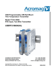
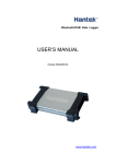
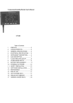
DIGITAL MULTIMETER
AX-101
OPERATION MANUAL
GENERAL
The instrument is a pocket digital multimeter, which be used to measurement
DCV, ACV, DCA, resistance, diode and continuity test. The instrument is an excellent ideal tool for
labs; household and wireless enthusiast.
SAFETY NOTES
1. Do not input a limited value when measuring ranges.
2. Voltage less than 36V DC and 25V AC is a safety voltage. When measuring voltage higher
than DC 36V, AC 25V, check the connection and insulation of test leads to avoid electric shock.
3. Be sure to keep the test leads off the testing point when converting function and range.
4. Don’t input the voltage value when measuring resistance.
SPECIFICATION
1.GENERAL
Displaying:
Max. indication:
Sampling rate:
Over range indication:
22mm data height LCD display
1999 (31/2), auto polarity indication
approx. 3 times/sec
MSD display “1”
” symbol displays
Low battery indication:
“
Operation environment:
0 ~4 0℃, relative humidity < 80%
Store environment :
Power:
Measurement:
Weight:
Accessories:
-10 ~ 50 ℃, relative humidity < 80%
one 9V battery (NEDA1604/6F22 or equivalent)
140x65x40 mm (lengthxwidthxheight)
approx. 180g (including a 9V battery)
operation manual, gift box, test lead and a 9V battery
2. TECHNICAL DATA
Accuracy:
±(a% × reading + d)
Surrounding:
( 23 ± 5),℃, relative humidity<75%. Guaranteed for one year
since production data
DCV
RANGE
200mV
2V
20V
200V
600V
ACCURACY
±(0.5%+4)
±(1.0%+5)
RESOLUTION
100uV
1mV
10mV
100mV
1V
Input resistance:1M Ω for all range
ACV
RANGE
200v
600v
ACCURACY
±(1.2%+10)
RESOLUTION
100mV
1V
Input resistance:1MΩ
Frequency response:40~400Hz
2
DCA
RANGE
2mA
200mA
10A
ACCURACY
±(1.5%+3)
±(2.0%+5)
RESOLUTION
1uA
100uA
10mA
Max. input current: 10A (within 10 seconds)
Overload protection: 0.2A / 250V self-resume fuse, 10A/250V fast melt fuse.
RESISTANCE (Ω)
RANGE
200 Ω
2k Ω
20k Ω
200k Ω
20M Ω
200M Ω
ACCURACY
±(0.8%+5)
±(0.8%+3)
RESOLUTION
0.1 Ω
1Ω
10 Ω
100 Ω
±(1.0%+15)
±[5.0%(1.0%+15)]
10k Ω
Note: For the range of 200Ω short-circuit test probes together to measure the resistance of the test
leads and then subtract it from the real measurement result.
Diode and continuity testing
RANGE
DISPLAYING
Forward voltage drop of diode
Buzzer makes a long sound
while resistance is less than
(70±20)Ω
TESTING CONDITION
Forward DCA is approx. 1mA,
the backward voltage is approx
3V
Open voltage is approx. 3V
Overload protection:DC 250V or AC peak value.
Bartery test:
At 1.5V range, overload inside is 15Ω, working current is 100mA
At 9V range, overload inside is 900Ω, working current is 10mA
3
PANEL DESCRIPTION
1.
2.
3.
4.
5.
LCD displaying:display the value and unit,
knob switch: change the test function and range,
10A current test jack,
Voltage, resistance, current jack: less than 200mA current test jack,
GND
DC Voltage Measurement
1. Apply the black test lead to “COM” terminal and the red one to V/Ω terminal;
2. Set the knob to a proper DCV range, and connect the leads crossly to the electric circuit under
test; LCD displays polarity and voltage under test connected by the red test lead.
Note:
1. Firstly users should set the knob to the highest range, if users had no idea about the range of
voltage under test, then select the proper range based on displaying value.
2. When LCD displays icon “1”, meter is over range thus should set the knob to a higher range.
3. Max. input voltage is 600V, over it might damage the circuit.
4. Please avoid touching high voltage circuit when measuring it.
AC Voltage Measurement
1. Apply the black test lead to “COM” terminal and the red one to“V/Ω“terminal;
2. Set the knob to a proper ACV range, and connect the leads crossly to the electric circuit.
Note:
1. Firstly users should set the knob to the highest range, in the case of no idea about the range of
voltage under test, and then select the proper range based on displaying value.
2. When LCD displays icon “1”, meter is over the max. Value of range thus should set the knob to
a higher range.
3. Max. input voltage is 600Vrms, over it might damage the circuit.
4. Please avoid touching high voltage circuit when measuring it.
DC Current Measurement
4
1. Apply the black test lead to “COM” jack and the red one to “V/Ω/mA” jack (Max. 200mA), or the
red one to “10A” jack(Max.10A);
2. Set the knob to a proper DCA range, and connect the leads in series to the electric circuit
under test, LCD displays polarity and current value under test connected by the red test lead
Note :
1. First, set the knob switch to the top range if you do not know the approximate value of the
measured current, and then select the appropriate range based on the displayed value.
2. If the LCD shows only "1", it means that the measuring range has been exceeded. Select a higher
range using the knob switch.
3. Max. input current is 200mA or 10A (depends on the insert position of the red test lead), over
large current will melt the fuse. When measuring, if the meter is no reading display, please check
the relevant fuse.
Resistance measurement
1. Apply the black test lead to “COM” jack and the red one to “V/Ω” jack;
2. Set the knob to a proper resistance range, and connect the leads crossly to the resistance under test.
Note :
1. The LCD displays “1”, while the resistance is over the selected range. The knob should be
adjusted to a higher range. When resistance under test is over 1MΩ, reading shall be stable in a few
seconds, which is a normal status when measuring high resistance.
2. When input terminal is in open circuit, overload displays.
3. When measuring in line resistor, be sure that the power is off and all capacitors are released
completely.
4. Do not input voltage at the range of resistance, it is forbidden absolutely.
Diode and Continuity test
1. Apply the black test lead to “COM” terminal and the red one to V/Ω terminal (the polarity of red
lead is “+”) ;
”range, connect test leads to the diode under test, the red test lead
2. Set the knob to“
connect to diode positive polarity, the reading is the approx. value of diode forward volt drop.
3. Apply test leads to two points of tested circuit, if the inner buzzer sounds, the resistance is less
than (70 ± 20) Ω.
Battery test
Set the range to :1.5V” or “9V”, it can test if the “1.5V” or “9V” battery has enough
working current, thus can judge the quality of battery.
MAINTENANCE
Do not try to modify the circuit.
NOTE:
1. Do not input voltage over than DC 600V or AC 600Vrms;
2. Do not measure a voltage on range Ω;
3. Be sure to fit on the battery correctly and close the cabin before taking measurement;
4. Remove the test leads off testing points and turns off the meter before replacing battery or fuse.
BATTERY REPLACEMENT
5
NOTE: Pay attention to the battery status. Please replace the battery as following steps when
the icon “
”displays:
1. Open the back cover.
2. Replace a new battery with 9V. An alkaline battery is recommended because of its good
capacity.;
3. Fix back cover.
FUSE REPLACEMENT
Please use the same size fuse as replacement.
• The specifications are subject to change without notice.
• The content of this manual is regarded as correct, error or omits Pls. contact with factory.
• We hereby will not be responsible for the accident and damage caused by improper operation.
• The function stated for this User Manual cannot be the reason of special usage.
MB-0203-01
6