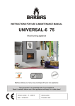
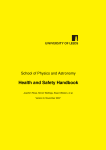
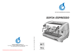
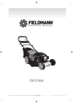
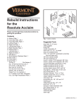
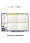
1
USER MANUAL FOR
23kW SUPER VULCANO PELLET STOVE
Table of Contents
1.Warnings ...........................................................................................1
2.Safety Instructions .............................................................................1
3.Safety Distances ............................................................................... 2
4.Stove Connection to the Chimney ......................................................3
5.Pellet specifications .......................................................................... 5
6.Display .............................................................................................. 6
7.User Menu ........................................................................................ 8
8. Technical Characteristics ................................................................14
9.The First Ignition of the Pellet Stove ..................................................14
10. Pellet Power Settings ....................................................................17
11. Set Temperature Settins.............. ................................................. 17
12. Pellet Loading Correction ............................................................. 18
13. Cleaning and Maintenance ...........................................................18
14. Appendix ...................................................................................... 22
ABC PROIZVOD D.O.O.
Miloša Obrenovića 2
31000 Užice
telefoni: +381 (0)31 514 501. 514 502
e-mail: offi[email protected]
1. WARNINGS
The User Manual constitutes an integral of the product. Should the
User Manual be damaged or lost, ask your installer or dealer to
provide you with the full set of undamaged instructions. The product
must be installed by a qualified installer, what implies full responsibility
and the first ignition. The installer must comply with all national,
regional and local regulations and standards in the country in which
the product is to be installed.
2. SAFETY INSTRUCTIONS
§ The stove must not be operated by persons (including children)
§
§
§
§
§
§
§
§
§
with physical disabilities and mental disorders.
Children must not play with the product.
Take care that the power cable is not in contact with hot parts of
the stove.
Do not use flammable liquids to fire up the stove.
The stove must be installed on the floor that may support its
weight.
Do not fire up the stove before connecting it to the central heating
system.
Do not insert pellets by hands into the burner
The stove shall be installed so as to allow undisturbed access for
thorough cleaning of the stove and chimney.
For safety reasons, do not open the stove doors when operating.
When adding pellets take care that the pellet does not fall into the
stove parts under high temperatures. Otherwise, pellet will start to
burn and smoke will appear in the room.
Load the stove when it is cooled.
§ When operating the stove must be always connected to the mains
voltage (230V). Should unexpected power failures occur, install the
UPS that will provide voltage for undisturbed stove shutdown and
prevent smoke from entering the room.
Danger to health and life of people in the room if no UPS is
provided.
1
2.1 List of Safety Devices
§
§
§
§
§
§
§
§
Safety valve
Thermostatically controlled pump
Water temperature indicator (display)
Water pressure indicator (display)
Minimum and maximum pressure indicator
Safety thermostat (water thermostat)
Expansion vessel
Safety pressure switch
The product is designed for the installation on the closed central
heating system
3. SAFETY DISTANCES
Designations
Flammable objects
Non-flammable objects
A
200 mm
100 mm
B
1500 mm
750 mm
C
200 mm
100 mm
Flue pipe
Fresh air intake
Opening for cleaning
S=floor protection
( Figure 1. )
( Figure 2. )
2
4. STOVE CONNECTION TO THE CHIMNEY
RIGHT
Indoor chimney
Outdoor chimney
Insulated part with
the hole for cleaning
(Figure 3.)
WRONG
Ash accumulation
Ash accumulation
(Figure 4.)
3
WARNING:
§ The horizontal line of flue pipes must have a slope of minimum 3%.
§ The horizontal line length of flue pipes must be minimum and no
longer than 3m.
§ The number of flue pipe elbows and T-fittings must not exceed 4.
4.1 Combustion air
Every combustion process requires oxygen or air. The air taken
from the room must be compensated. The loss of oxygen may occur
in modern houses with high insulation efficiency and perfectly sealed
windows and doors. Unless the stove is connected to fresh air intake,
the room in which the stove is installed shall be more frequently
ventilated.
4.2 Supply of fresh air for combustion
§ The stove structure has a connection on the back side.
§ The fresh air supply pipes may be steel or aluminium. The
minimum diameter amounts to 50 mm.
§ The maximum pipe length shall not exceed 4 m in order to ensure
adequate supply of fresh air. The pipes shall not have too many
elbows.
§ A failure to provide some of the specified conditions may result in
poor combustion and vacuum generation in a room.
4
5. PELLET SPECIFICATIONS
What is pellet?
The wooden pellet is standardized fuel. Every manufacturer must
comply with certain rules in order to provide highly energy efficient
heating.
Please check with your local dealer for the list of manufacturers of
attested pellets. The use of poor quality pellets may have a
negative impact on the stove operation. The recommended
standards for pellet quality are: ÖNORM, DIN Plus or ENplus-A1.
Specification of wooden pellets in accordance with En plus - A1
Parameter
Unit of Measurement
Enplus-A1
Diameter
mm
6
Length
mm
3,15 do 40
Bulk density
3
kg/m
600
Calorific value
MJ/kg
16,5
Water content
Max %
10
Ash residue
Max %
0,7
Chlorine content
Max %
0,02
Sulphur content
Max %
0,03
Nitrogen content
Max %
0,3
Copper content
mg/kg
10
Chromium content
mg/kg
10
Arsenic content
mg/kg
1
Cadmium content
mg/kg
0,5
Mercury content
mg/kg
0,1
Lead content
mg/kg
10
Nickel content
mg/kg
10
Zinc content
mg/kg
100
5
5.1 Storage of Pellets
It is very important that the pellets are stored at the dry place. It is not
advisable to store pellets in bags exposed to atmospheric conditions.
Too wet pellets may block the auger or stove operation.
6. DISPLAY
Figure 5 shows the Touch Screen Display with all designations and
the meaning of each element.
Time and Date
Current Water Temperature
Time settings
Operating Mode
Alarm number
Combustion Power
Set
temperature
Stove Condition
Led zone
Start – Stop
Settings
(Figure 5.)
6
Main Menu
Info
Meaning
Designations
Firing up the stove if the button is pressed
for 3 seconds
Stove shutdown and alarm reset if the button is
pressed for 3 seconds
Access to the Settings Menu
Access to the Main Menu
Access to the Info Menu
Designations
Meaning
Return to the Home Screen
Return to the previous level
Moving through the Menu
Value increase
Moving through the Menu
Value decrease
Exit the Menu and save values
Exit the Menu without saving values
Move to the left
Move to the right
The LED zone is not always visible on the main screen. By pressing
the central display zone, the led designations become visible. The led
designations shall disappear from the screen by pressing the display
again.
7
Meaning
Designations
Heater ON
Motor-reducer ON
Circulating pump ON
Solenoid valve open
Output V2 ON
Output Aux 2 ON
Output Aux 3 ON
Visualization:
By pressing the info button
the visualisation settings are accessed.
Exhaust T:
Temperature of exhaust gases (C°)
Water T:
Water temperature in the boiler (C°)
Pressure:
Water pressure in the boiler (mbar)
Fan speed:
Fan speed (rpm)
Auger:
Motor-reducer (s)
Recipe:
Mode (r.b.)
Product Code 480–00.00
Product code
7. USER MENU
The Settings Menu is accessed by pressing the button P
The menu configuration is as follows:
8
.
Description
Menu contents
Functioning
Combustion
Management
Heating
Management
Pellet Power
Combustion power setup menu
Wood Power
Not in function
Pellet Recipe
Not in function
Auger Calibration
Setup menu for the motor-reducer uptime
Fan Calibration
Fan speed setup menu
Boiler Thermostat
Setup menu for the maximum and minimum
temperature in the boiler
Buffer Thermostat
Setup menu for Buffer temperature. Available only if
P26=2,3,4,8 and P79=9
Summer-Winter
Summer – Winter Switch Menu
Heating Power
Not in function
Climatic Function
Climatic Function Setup Men. Available only if P74>7
Mixer Valve
Mixer Valve Setup Menu. Available only if P26=7.8
Menu for setting up the time interval for stove switching
on and off
Chrono
Remote
Keyboard
Menu for changing combustion modes
Room Thermostat
Room thermostat setup menu. Available only if A52=0
Enable
Enable and disable the room thermostat
Manual Load
Activation of the manual load option during the first
start-up or after no pellets are left in the hoper.
Reset Service
Not in function
By pressing the button
following configuration:
you will enter the main menu with the
Description
Menu Contents
Keyboard
Setting
Display/
Keyboard Menu
System Menu
Date and time
Time and date settings
Language
Selection of the preferred language
Display Light
Screen brightness adjustment
Keyboard Address
RS 485 Setup Menu
Node List
Menu for the communication of addresses on the board,
board type and software version
Technical Menu. Password protected. The access only
allowed to the authorised service centre.
9
7.1 Chrono Menu – Time setting
The menu is designed to set the timing of stove start-up and
shutdown.
§ To set the time settings press the "Chrono" button in the upper
right corner of the screen.
Time
settings
Time
settings
enabled
Select
the
desired
program
§ In order to enable/disable the time settings, press "Enable
CHRONO".
§ If the chrono function is disabled the light is off
this function is enabled, the light is red
. However if
.
§ To select the desired program press one of the following options:
§ "Enable daily mode", "Enable weekly", "Enable week-end".
§ If the programming is disabled the light is turned off
programming is enabled the light is green
.
§ To set time press "Edit timetable".
§ To exit the Chrono menu press the button
10
.
If the
7.2 Time Settings
§ By pressing "Edit timetable" you will access the cards for time
settings for each of the offered modes.
§ By pressing the left
§
§
§
§
§
§
§
§
or right
arrow in the first row, we
choose between the three offered modes: “daily mode”,”weekly",
and ”week-end".
By pressing the left
or right
arrow in the second row we
select the day or group of days in the week based on the
previously selected the program mode.
You may choose any day of the week within the daily mode:
Monday, Tuesday, Wednesday, Thursday, Friday), Saturday and
Sunday.
Only one group of days may be selected for the weekly mode:
Monday-Sunday.
The two groups of days may be selected for the week-end mode:
Monday-Friday and Saturday-Sunday
To exit the "Edit timetable” menu press
To enable/disable the selected time press the lamp indicating the
desired time
If the time settings option is disabled the lamp is turned off
and
if the time settings option is enabled the light is red.
11
Stove On Time
Stove Off Time
§ The card shows the day or group of days of the week as well as
§
§
§
§
time settings. The time on the left side shows the stove on time,
while the time on the right side shows the stove off time.
To increase the time value press and to decrease the time value
press
To save the set time value and exit the menu press
If you want to exit the menu without saving data press
The saved time settings for all three program modes are
separately memorized. Therefore, should the data related to the
daily mode be changed, the weekly and weekend modes will not
be changed.
7.3 Time and Date Settings
§ To display time and date press the “Time and date” zone on the
main screen.
§ To increase the value press
in the upper
row
§ To decrease the value press
in the
bottom row
§ To save the set values and exit the menu
press
§ To exit the menu without saving values
press
12
7.4 Alarms
Alarm
Description
Er 01
Safety Thermostat HV 1
Er 02
Safety Pressure Switch HV 2
Er 03
Shutting down due to the low temperature of exhaust gases / high
temperature in the hoper
Er 04
Shutting down due to too high water temperature
Er 05
Shutting down due to too high temperature of exhaust gases
Er 07
Encoder error
Er 08
Encoder error. This error may occur due to the setting of round numbers.
Er 09
High water pressure
Er 10
Low water pressure
Er 11
Clock error in the real time
Er 12
Shutting down due to the failed ignition
Er 15
Lack of electricity
Er 16
Communication error RS485
Er 17
Error in the air flow regulator
Er 18
Lack of pellets
Er 23
Active probe of the boiler, buffer or return line
Er 25
Faulty motor for burner cleaning
Er 26
Faulty motor for cleaning
Er 27
Faulty motor for cleaning 2
Er 34
Vacum is below the minimum
Er 35
Vacum is above the maximum
Er 39
Faulty sensor of the air flow regulator
Er 41
The minimum air flow in the Check-up phase has not been reached
Er 42
The maximum air flow has been reached (F40)
Other messages:
Sond
Service
Clean
Ignition Block
Er 20
Visualisation of the condition of temperature probes
Notification that the defined period for product servicing has expired
Notification that it is time to clean the product
This message will appear if the system has been shut down in the ignition
period by en external device: the system stops when enters operation phase
Grid sensor open
Door
Open door
Er 06
Pellet thermostat active
Link Error
Error in communication between the motherboard and display
13
8. TECHNICAL CHARACTERISTICS
Characteristics
Value
Efficiency ratio (%)
90,1
Height (mm)
1254
Width (mm)
589
Depth (mm)
763
Weight (kg)
244
Min-max stove power (kW)
8-23
Water volume (l)
25
Hoper capacity (kg)
50
Operation autonomy (Max/h - Min/h)
31 - 13
Flue pipe diameter (mm)
120
Necessary draught (Pa)
5
Pellet consumption (Min - Max)
1,6kg/h - 4kg/h
Connection lines (Col)
1"
Electricity consumption
Ignition phase (W)
450
Operation phase (W)
50
Power supply (Vol - Hz)
230 Vol - 50 Hz
9. THE FIRST IGNITION OF THE STOVE
§ Super Volcano pellet stove is factory equipped with the circulating
pump, expansion vessel, safety valve and automatic air vent. The
stove is to be connected to the central heating system by
discharge and return line pipes as shown in Figure 6.
14
(Figure 6.)
A
Safety valve
B
Outlet line
Hot water
C
Connection for the flue pipe
Ø 120mm
D
Return line
Cold water
E
Connection for the fresh air supply
3bar
1
Safety valve discharge drain
2
Thermometer
3
Pressure gauge
4
Balance valve
5
Thermostatic mixing valve 55°C
6,8,9
7
10
Ø 60mm
Valve
Installation refilling system
Drain to the sewer
Prior to the stove first ignition make sure that:
§ All tools are removed from the stove (user manual, power cable)
§ The stove is connected to the pipeline and filled with water
§ The air vent cover under the stove cover is open
§ The flue outlet is connected to the chimney
§ The door is closed and the ash trap is place
§ The hopper is loaded with pellets
15
§ The power cable is connected to the mains (220V) and the stove
is turned on via the main switch on back side of the stove
§ The auger is filled with pellets in the following manner (the hoper
must be loaded with pellets):
1. Press
on the main screen
2. Press “Manual Load”
3. Press “ON”
4. This function is active for 30 seconds. Monitor the section where
pellets enter the burner through the firebox doors and when the
first pellet grains occur turn this function into “Off’. If necessary,
repeat this action until the pellets start to enter the burner.
NOTE:
This function is to be used when the stove started up for the first time
or when there are no pellets in the hoper (there are no pellets in the
auger)
5. A long press on the field
ignition process
(3 - 4 seconds) activates the stove
9.1 Safety Function of the Door
For safety reasons the upper door cannot be open during the stove
operation. As shown in Figure 7 it is required to close the upper
door first and then the bottom door.
NOTE:
For the purpose of ensuring
reliable operation, the upper
and bottom doors must be
locked
Upper door latch
(Figure 7)
16
10. PELLET POWER SETTINGS
Press
on the main screen.
Press the field “Combustion Management” and then “Pellet Power “
Select the desired power by pressing the card (from 1 to 5) or select
the automatic mode on the next page (press ). The automatic mode
is reflected in the following:
- The pellet power is automatically selected based on the set
temperature and current water temperature in the boiler:
Example:
Set T
Water T C°
≤70
71
72
73
74
≥75
Pellet power
5
4
3
2
1
Modulation
To return to the home screen press
11. SET TEMPERATURE SETTINGS
Press
on the main screen.
Press “Heating Management” and then “Boiler Thermostat”.
or
increase or decrease the value .The limit values range from
50°C to 80°C.
To return to the home screen press
17
12. PELLET LOADING CORRECTION
This function shall be used to fine tune the pellet power. If the power 5
is too high and power 4 insufficient, the power shall be corrected from
5 to - 1,2,3 so as to obtain the power between 4 and 5.
Press
on the main screen.
Press “Combustion Management” and then “Auger Calibration”
or
increase or decrease the value from 0 to 5. To return to the
Home screen press
NOTE:
If the pellet loading correction is to be made it is also necessary to
correct the fan speed “Fan Calibration”. Should the pellet
correction be + the fan correction must also be + for the same value.
The stove is factory set for flawless operation. Should the high
quality pellets be used, there will be no need to make corrections.
13. CLEANING AND MAINTENANCE
Basic Information
The stove must be off and completely cooled before starting any
cleaning and maintenance activity.
The stove cleaning and maintenance intervals primarily depend on the
pellet quality. The wet pellets contain a high percentage of ash, dust
and unburned residues, which double the cleaning and maintenance
intervals. Therefore, we would like to emphasize once again that only
attested and certified pellets shall be used. The stove is equipped with
a removable handle for opening the firebox door. Having closed the
door, the handle shall be laid next to the stove in order to prevent the
possibility of door opening during the operation as well as handle
overheating. Cleaning is divided into three categories: Daily, Weekly
and Monthly.
18
Daily Cleaning
Super Volcano pellet stove is equipped with the automatic system that
controls the periodic mechanical cleaning of the burner. However, it is
recommended to remove ash residue from the burner by a vacuum
cleaner every 2-3 days.
( Figure 8)
To clean the heat exchanger, the crank may be pulled only when the
stove is cold. In order to ensure the undisturbed energy transmission
to water, the cleaning operations shall be performed on a daily basis.
The crank is to be pulled a removable handle (Figure 8) which is also
used for (pulling) cleaning the heat exchanger turbulator. It is
necessary to pull the turbulator cranks several times (3-4) up and
down.
( Figure 9)
19
Weekly Cleaning
Clean the firebox and ash trap from ash:
§ empty the ash trap on a weekly basis or more frequently as needed
§ pull the flame deflector up and outward (Figure 9)
§ it is recommended to vacuum clean dust and ash in the firebox
section minimum once a week by using the adequate vacuum
cleaner
(Figure 10)
Flame deflector
Monthly Cleaning
The deflector of flue gases positioned atop the firebox must be
removed and cleaned at least once a month. The deflector dismantling
is very simple. The deflector shall be pulled onward and downwards
as shown in Figure 10. It shall be returned to its place in a reverse
order.
NOTE: The stove is to be cleaned only when it is completely cooled
Flue gas deflector
(Figure 11)
20
The flue gas duct shall be cleaned once every two months or at the
end of the heating season depending on the stove mode and pellet
quality.
The cleaning opening is to be assessed by pulling the bottom part of
the cover onward, removing the couplings and then by pulling it down
(Figure 12)
Cover of the opening for cleaning
(Figure 12)
§ Clean the ash layers from the left and right chamber by a vacuum
cleaner
§ Return the cover of the cleaning opening into its place and tighten
all four screws
In order to guarantee safety and reliable operation of the stove the
operations specified below must be performed at the end of every
season or more frequently, if needed:
§ Seals allow proper stove operation only when they are
undamaged and adequately set
§ Seals must be periodically inspected. Should seals be worn of
damaged, they must be immediately replaced.
§ Flue pipes must be cleaned and vacuum cleaned once during the
season or more frequently, if needed. If there are horizontal lines,
ash shall be cleaned before it blocks the passage of flue gases
and causes stove downtime.
Hoper Cleaning
Do not load pellets unless you vacuum cleaned the residues of the
previously used pellet quantities (dust, fine pellet waste, etc.)
21
14. APPENDIX
CE Declaration of Conformity:
Manufacturer
„ABC PROIZVOD“ doo
Miloša Obrenovića 2
31000 Užice/ Srbija
Hereby declares that the pellet stove: Super Volcano, conforms to the
CE requirements and provisions (Construction Products Directive) 89/
106/ EEC as well as the following harmonized standard:
EN 14785
In 2007, ABC PROIZVOD doo, Užice implemented the quality
management system
SRPS ISO 9001/ 2008, which is maintained and improved.
Another 2 standards have been implemented since 2013:
SRPS OHSAS 18001/ 2008 and
SRPS ISO 14001/ 2005, therefore, the company has an
INTEGRATED QUALITY MANAGEMENT SYSTEM certified by the
accredited body.
14.1 Certificates
22