1
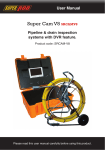
Specifications
PIPELINE & DRAIN INSPECTION
SYSTEMS WITH DVR FEATURE
ASSEMBLY AND OPERATING INSTRUCTION
Item
Description
Battery Case
LI-ON BATTERY
Maximum Camera Depth
60□120□M Cable
Camera Light Source
Built-in White LED(30PCS)
Camera Angle-of-View
120°
Camera Depth-of-View
400 mm (approximate)
Camera Image
Color
Monitor Image
Color
Monitor Picture Resolution
420 (TV Lines)
Monitor Input Voltage
12 Volts DC
System Operating Temperature
-20°to 120°F
Meter Counter
Metric & Imperial
Save this Manual
Attention
1. Read the user manual carefully before using this system.
2. Avoid using the device in extremely cold, heat, or humidity environment, it may damage
the device.
3. Do not drop or press hard on the device.
4. Warranty avoid if the device is opened by users or has physical damage.
5. Always back up your date before connecting your SD device to this system. The
manufacturer is not responsible for any date damage on your SD device for any reason.
6. Do not disconnect the unit while recording or playing. It may damage the unit or the SD
device
Read these instructions completely before operating this system
1
Attention
Camera
WITH AUTO BALANCE CAMERA FOR PIPELINE & DRAIN INSPECTION .
1. WATER SUPPLY
2. WASTE WATER
3. ELECTRICAL AIR-CONDITION
4. CABLE DUCTING
5. DUCTED VACUM SYSTEMS
6. IN BUILDING
1. WHITE LEDS
2. LENS
3. SPRING
4. SKID
1
2
3
4
Know Your Tool
Cable wheel
1. COUNTER BOX
2. METRIC & IMPERIAL BUTTON
3. RESET BUTTON
4. CABLE TRAY
5. FEMALE PLUG
6. BRACKET
7. CABLE WHEEL
8
9
1
1.
2.
3.
4.
5.
6.
7.
2
3
4 5 6
RECEIVER
AV BUTTON
LIGHTS CONTROL
MENU SELECTOR
VV+
POWER SWITCH
7
6
8. DC IN
9. DC OUT
10. VIDEO IN AV2
11. VIDEO OUT
12. CAMERA AV1
13. SD DEVICE
14. DVR DEVICE
15. SUNSHADE
16. RECHARGEABLE BATTERY
2
1
2 3
4
3
7
5
System Set-Up
SKID AND CAMERA MOUNT
1. IMPORTANT: When connecting the Camera to the Monitor the power must be off or both
units will be damaged.
2. Screw the Camera to the Wheel Cable (See Figure1- A) & Connect the Wheel to the
Monitor (See Figure 1-B) .
3. Plug the Power Adapter cord into the wall AC socket and other end into the DC 12V-Input
Jack ( Power Adapter Optional ) or plug the cord from the Battery Box into the DC 12V-Input
Jack (See Figure1- C).
4. Turn on the POWER Switch on the front of the Monitor.
5. Gently lower the Camera into a pipe duct, etc and reel out the Cable until it is at the
desired depth.
6. Record the pictures if you need (see DVR Operating).
7. Video Out: By a video cable you can transfer the picture to other larger Screen.
8. When finish, carefully remove the Camera from the pipe duct, etc, clean it with a clean,
soft and dry cloth then put the Camera into the previous position.
A
C
RESET/METRIC & IMPERIAL BUTTON
B
CABLE TRAY CONDITION
Figure 1
4
5
DVR operation
Fast forward and rewind
1. Set the Screen AV Button on Video 2.
2. Take off the isolation sheet from the Remote Control Battery.
3. Press the Remote Control Button 5
to Power On the Recording system, you can see
DVR power LED turn on & PLAY VIDEO manual on the screen.
4. Insert your SD flash or removable hard disc etc to the SD Port, you will see SD
CONNECTED on the screen & the SD LED light on.
5. Press Remote Control Button 3
to start the recording & the RECORDING LED light
turn on.
6. Press Remote Control Button 7
to stop the recording.
7. Press Remote Control Button 1
to review the recording.
8. If you need to manage your recording pictures, press Remote Control Button 4
,also
you can do this files management by electing the SETTING on PLAY VIDEO manual on the
screen.
User can use or button on the remote control to fast forwarding or rewinding (1x, 2x, 4x,
or 8x, speed).Always press button to go back normal playing.
Compatible video format:
Divx3.11/Divx4/Divx5/MPEG1/MPEG2/MPEG4 (MPEG4 video file format: .avi,
.m4v, .MPG, MPEG, .VOB)
Note: video does not support many downloaded video.!
STOP
SETUP
System setup
User can select different standard, recording and other features during the setup.
Also user can upgrade the unit firmware or restore to factory setting.
Schedule recording
User can schedule a recording in advance. Simply enable the schedule recording in the
SETUP. Then the unit will ask user to setup timing. See chapter 6 for more details.
Recording schedule can be used . User has to set up schedule again for next recording.
Recording to SD device
Recording setup
Video standard: PAL or NTSC (default NTSC)
Resolution: 640*480,480*360,720*480 and 320*240(default 640*480)
Compression rate: 1000, 1200, 1500, 1800, 2100, 2500KB/S (default 1000kb/s)
Sample frequency: 24.32khz(default 32khz)
Schedule recording: on/off (default off)
The unit is able to record video into SD devices such as SD hard disk .The recorded video
will be stored in the SD devices and played back on the TV screen.
Recording format
The default recording resolution is 640*480, which takes about 500MB/hour. User may
select 320*240 to save storage space.
Video play
User can use on-screen menu to enter “play video” mode. The unit will display the recorded
video and other compatible videos inside SD device.
It will not list the non-compatible videos.
Select the video file.
When user enters “play video” mode, the set will display all of the available video files on TV
screen.
User will use [ ] or [ ] button to select desired video and press button to play.
Press and hold [ ] or [ ] button to go to previous or next video.
Use
button to start or pause the playing .Use [STOP] button to stop or go back to
previous menu.
The screen will display “loading, please wait …” for few seconds before playing video.
6
7
Recharge
Assembly drawing and parts list
1) Plug the AC cord into wall AC socket & insert the other end into the Battery Box AC jack
(See Figure2- A)
2) Press down the charge switch (See Figure2-B)
3) Charge LED will be Red during charging & turn to be Green when finish charging
(normally charging time 5-6 hours).
Part No.
A
AC CORD
C
CHARGE LED
Description
1
AUTO BALANCE PICTURE CAMERA
2
MONITOR
3
60□120□M CABLE
4
AC CORD
5
BATTERY CASE
6
BIG CASE
7
SUNSHADE
8
SKIDS (3PCS)
9
CONNECT CABLE (1.5M/3M/5M)
10
REMOTE CONTROL
11
DC 12V POWER ADAPTER (OPTIONAL )
B
CHARGE SWITCH
Figure 2
REMARK:
3
2
8
1
7
9
1. TOTAL POWER
14 W
2. LITHIUM BATTERY 12 V DC MAX.≦ 4.5 AH
3. CHARGER
12.9 V
1A
4. CHARGE TIME
5
HOURS
5. WORK TIME
≥200
MINUTES
6. PROTECTIVE VOLTAGE 8.1 V
7. THE VOLTAGE BEFORE DISCHARGING 12.6 V
8. LOAD CURRENT 1100 MA(INPUT 12.2 V)
8
4
6
5
9