1
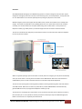
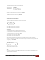
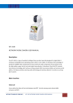
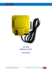
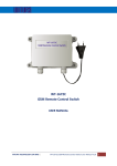
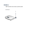
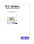
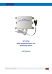
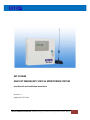
WT‐1010LM GSM LIFT EMERGENCY VOICE & MONITORING SYSTEM User Manual and Installation Instructions Version: 1.1 Updated: 27 OCT 2011 WITURA CORPORATION SDN BHD | GSM Lift Emergency Voice & Monitoring System Instruction Manual 1 Overview: WT‐1010LM GSM Lift Emergency Voice & Monitoring System is a wireless emergency communication system designed for emergency calls from a lift cabin to the monitoring centre, service department, security personnel etc. over GSM network. The unit works perfectly with any emergency lift phone in the market. GSM lift emergency voice system applies because GSM call cost is better than landline and no monthly fixed charges. This system also applicable in every building where there is no person who monitors lift’s condition constantly. It is the ideal solution for companies which have greater number of lifts – all they need is one telephone number (e.g. mobile phone’s) on which messages and voice connections will be transferred. The unit also suitable for offer temporary communication solutions at construction sites where the telephone line has not yet been installed. Lift Control Room When a trapped lift passenger presses the button on the lift phone for emergency, the lift phone automatically calls up an alarm centre or security personnel number via the GSM network. When voice communication is established the person can talk to the staff at the alarm centre where help will be dispatched. The unit also the reporting and monitoring system provides monitoring the working status of lift and escalator over GSM network. When there is a failure or power failure, the WT‐1010LM GSM unit will automatically generate SMS alert to the pre‐programmed telephone number (up to 8). The system has 2 low voltage alarm inputs which can be connected to the lift for alarms about Panic situation, lift functionality etc. It is also possible to remotely control the 2 30A output relay of the GSM Emergency Lift Dialler to reset the lift or to completely shut down the lift. WITURA CORPORATION SDN BHD | GSM Lift Emergency Voice & Monitoring System Instruction Manual 2 Features: Support Dual‐Band or Quad‐Band GSM Network Can connect to existing lift phone for emergency call LCD Display for indication of calling number Programmable by PC or SMS command SMS alert during lift power failure Remotely control of 2 output relays contacts for lift reset/switch off lift by SMS 2 low voltage inputs for sending SMS alerts when input changed state (High/Low) 1 independent output for activating the strobe light/siren when power failure Battery Backup for up to 6 hours in event of power failure Check signal strength via SMS Configurable SMS alert content WITURA CORPORATION SDN BHD | GSM Lift Emergency Voice & Monitoring System Instruction Manual 3 INTERNAL VIEW LCD Display SIM Card Holder RF Receiver GSM Module Main Switch Jumper DC Power Connector Phone Port Line Port Digital Inputs 2 Relay Outputs Antenna Connector WIRING DIAGRAM WITURA CORPORATION SDN BHD | GSM Lift Emergency Voice & Monitoring System Instruction Manual 4 PROGRAMMING THE UNIT To program the unit you just need any fixed line telephone and connect it to the TEL port on the GSM unit. Any fixed line telephone for programming GSM Emergency Lift Dialler ENTER PROGRAM MODE To enter program mode, pick up the telephone handset and dial **12345678# (default installer code) The display will show HAND FREE.... The GSM Unit is now in Programming Mode. To exit program mode simply hang up the handset. Program the Installer Code The installer code is used to access program mode via handset. To program a new 8 digit installer code simply press *0* in program mode. Enter the new installer code followed by # (eg. 87654321#) The display will show NEW PASSWORD: 87654321# To exit programming mode simply hang up the handset. NOTES: DO NOT LOSE THE INSTALLER CODE AS IT CANNOT BE RECOVERED IF LOST OR FORGOTTEN. YOU WILL NEED TO CONSULT WITH OUR TECHNICAL PERSONNEL FOR RESETTING THE SYSTEM TO DEFAULT STATE. Admin Phone Number 1 must be programmed to allow sending of SMS commands to the GSM Unit WITURA CORPORATION SDN BHD | GSM Lift Emergency Voice & Monitoring System Instruction Manual 5 ATTENTION: PROGRAMMING METHODS – HANDSET AND SMS COMMANDS Please note that some options are programmed using a telephone handset connected to the GSM unit and other options are programmed by SMS message sent from a mobile phone. SMS COMMAND options are programmed by sending an SMS message from a mobile phone to the GSM Unit. The mobile phone used to send SMS Commands must be programmed as Admin Phone Number 1. Program the Admin Phone Numbers Up to 8 Admin phone numbers can be programmed. These are mobile phone numbers to which the GSM Unit can send SMS messages, such as alarms from inputs or system messages. Here you should program the technical or security personnel numbers etc. You can program the unit to send SMS alarms to one or all Admin numbers. HANDSET In Program Mode Press *1* to program the Admin Phone Number 1. Enter the phone number followed by # (eg. 0124694739#) TEL: 0124694739 1# To program Admin Phone Number 2 to 8, repeat the sequence above using *2*, *3*, *4*, *5*, *6*, *7*, *8* To DELETE a Phone Number enter # with no phone number. eg. To delete Admin Number 1. HANDSET In Program Mode Press *1*# To program the Admin Phone Number by SMS send: SMS Command: *TEL[N]#[phone number] N = Admin position 1 – 8 [phone number] = Admin phone numbers WITURA CORPORATION SDN BHD | GSM Lift Emergency Voice & Monitoring System Instruction Manual 6 Example, to program phone number 0163934857 as “Admin 1” send: *TEL1#0163934857 The GSM unit will send this reply message: TEL1=0163934857 Enquire all Admin Phone Numbers To display all the Admin Phone Numbers locally using a handset. HANDSET In Program Mode Press *30* Each Admin Phone Number will be displayed in sequence: ADMIN: 1: 0124694739 To display all the Admin Phone Numbers by SMS. SMS Command: *ADM?# The GSM unit will send this reply message: Example: 1: 0124694739 2: 3: 4: 5: 6: 7: 8: WITURA CORPORATION SDN BHD | GSM Lift Emergency Voice & Monitoring System Instruction Manual 7 Area Code / Phone Number Prefix To program prefix digits which will be automatically dialled before any phone number. HANDSET In Program Mode Press *24* Enter the prefix (max. 4 digits) followed by # (eg. 04#) AREA CODE: 04 OK Note: Once programmed, the Phone Number Prefix cannot be deleted it can only be replaced by a new prefix. Use *25* option to enable and disable dialling of the prefix. Enable / Disable Phone Number Prefix Use this option to enable the dialling of the Phone Number Prefix. HANDSET In Program Mode Press *25* To enable the Phone Number prefix press 1# To disable the Phone Number prefix press 0# ENABLE AREA? Setting the Delay Time for Sending the Destination Number This setting enables the dialled destination number to be sent out automatically after a preset time. HANDSET In Program Mode Press *9* Enter the Delay time (Max. 2 digits) followed by # (e.g. 05#) WITURA CORPORATION SDN BHD | GSM Lift Emergency Voice & Monitoring System Instruction Manual 8 Dttransmit: 05 OK Program the Alert Recipients This option sets which of the 8 Admin Phone Numbers will receive SMS alerts. HANDSET In Program Mode Press *22* to select the option Enter either the digit 0 (No alert) or 1 (Send alert) for each of the 8 Admin Phone Numbers, followed by #. Example 1, to enable all Admin Numbers for alerts, press 11111111# SECH: 11111111 OK Example 2, to enable only Admin Numbers 1, 2 & 3 for alerts, press 11100000# SECH: 11100000 OK To program the alert recipients by SMS, send: SMS Command: *SECH#XXXXXXXX XXXXXXXX = stands for position of each of the 8 Admin Phone Numbers, Enter either the digit 0 (No Alert) or 1 (Send Alert) Example: to enable all Admin Numbers for alerts, send: *SECH#11111111 The GSM unit will send this reply message: SECH‐11111111 WITURA CORPORATION SDN BHD | GSM Lift Emergency Voice & Monitoring System Instruction Manual 9 Enquire the Setting of Alert Recipients Check the setting of alert recipients using a handset. HANDSET In Program Mode Press *35* The Alert Recipients will be displayed in sequence: SECH: 11110000 Setting the Calling Group of Administrator This setting will enable the system to call the certain group of administrator numbers when Input triggered or AC power failure. HANDSET In Program Mode Press *23* Enter the number 1 – 8 (Max. 1 digit) followed by # Example: to enable the system to call the first 3 administrator numbers, press 3# CALL: 3 OK Setting the Waiting Time for Engaged Call In the event the administrator has not answered the call or engaged, it could take a while for the WT‐1010C2 to call the next number. This setting allows you to shorten the waiting time when it is busy or engaged. HANDSET In Program Mode Press *31* WITURA CORPORATION SDN BHD | GSM Lift Emergency Voice & Monitoring System Instruction Manual 10 Enter the Waiting Time (Max. 2 digits in seconds) followed by # (e.g. 25#) Example: to program the waiting time as 25 seconds, press 25# Wait Time: 25 OK Note: The Waiting time range from 20 – 59 seconds (Default: 30 seconds) Program the AC Power Failure Options This function enables the possible alarm action for AC power failure. HANDSET In Program Mode Press *28* to program AC Power Failure alarm options AC Power Failure Options ME: Send SMS alert when power failure AL: Activate the strobe light when power failure CA1: Call Admin number when power failure CA2: Call Admin number when power restored Enter either the digit 0 (Disable) or 1 (Enable) for the 4 possible actions for the AC power failure alarm, followed by #. Example: To enable the system to send SMS alert and activate the strobe light when AC power failure, press 1100# ADC: ME:1 AL:1 CA1: 0 CA2: 0 OK Note: If the system calls you when the power failures simply answer the call and press # to acknowledge the alarm and the system will stop calling you. WITURA CORPORATION SDN BHD | GSM Lift Emergency Voice & Monitoring System Instruction Manual 11 AC Power Failure Message This option sets the SMS text content which is sent when AC power failure. *ACPF# [message content] SMS Command: [message content] = Up to 50 alphanumeric characters. Letters and numbers only, no special characters Example: To program the system to send SMS message “Lift Power Down”, send: *ACPF#Lift Power Down The GSM unit will send this reply message: ALOFF‐Lift Power Down AC Power Restored Message This option sets the SMS text content which is sent when AC power restored. *ACPR# [message content] SMS Command: [message content] = Up to 50 alphanumeric characters. Letters and numbers only, no special characters Example: To program the system to send SMS message “Lift Power Restored”, send: *ACPR#Lift Power Restored The GSM unit will send this reply message: ALON‐Lift Power Restored Enable/Disable the Alarm Input Function This option allows you to enable/disable the function of alarm input. HANDSET In Program Mode Press *16* to enable/disable the function of 2 alarm inputs To enable the function of 2 alarm inputs press 11# To disable the function of 2 alarm inputs press 00# CTR1: 1 CTR2: 1 OK WITURA CORPORATION SDN BHD | GSM Lift Emergency Voice & Monitoring System Instruction Manual 12 To Enable/Disable the Alarm Input Function by SMS, send: SMS Command: *CTR[N]#X [N] = Input number 1 or 2. X = 1 (Enable) or 0 (Disable) Example: To enable the alarm input 1 function, send: *CTR1#1 The GSM unit will send this reply message: CTR1‐ON Program the Alarm Input Options This option enables the possible actions of 2 alarm inputs of the unit. HANDSET In Program Mode Press *26* to program Input 1 alarm options Press *27* to program Input 2 alarm options Input Options OP: Send SMS Alert when Input Triggered (Alarm Input to +12V) CL: Send SMS Alert when Input Restored (Remove +12V from Input) AL: Activate Strobe Light / Siren when Input Triggered CA1: Call Admin number when Input Triggered CA2: Call Admin number when Input Restored Enter either the digit 0 (Disable) or 1 (Enable) for the five possible actions for the input, followed by #. Example: To enable Input 1 to send SMS Alarm and Restoral messages and activate the strobe light when input is triggered, press *26*11100# IN1: OP:1 CL:1 AL:1 CA1: CA2: OK Follow the same procedure for input 2. Note: If the system calls you when the input triggered simply answer the call and press # to acknowledge the alarm and the system will stop calling you. WITURA CORPORATION SDN BHD | GSM Lift Emergency Voice & Monitoring System Instruction Manual 13 Input Alarm Message This option sets the SMS text which is sent when an input is triggered. SMS Command: *USE[N]#[message] [N] = Input number 1 or 2. [message] = Up to 50 alphanumeric characters. Letters and numbers only, no special characters. Example: To program Input 1 to send the SMS message “Lift Function Open”, send: *USE1#Lift Function Open The GSM unit will send this reply message: USE1‐Lift Function Open Input Restoral Message This option sets the SMS text which is sent when an input is restored. SMS Command: *USC[N]#[message] [N] = Input number 1 or 2. [message] = Up to 50 alphanumeric characters. Letters and numbers only, no special characters. Example: To program Input 1 to send the SMS message “Lift Function Closed”, send: *USC1#Lift Function Closed The GSM unit will send this reply message: USC1‐Lift Function Closed Program the Strobe Light / Siren Output Duration To program the strobe light / siren output duration on PIN24 and PIN25. The alarm time can be set between 00001 to 99999 seconds. Note that programming duration of 00000 seconds has no effect. HANDSET In Program Mode Press *33* Example: To program the strobe light / siren output duration to 10 minutes, press *33*00600# WITURA CORPORATION SDN BHD | GSM Lift Emergency Voice & Monitoring System Instruction Manual 14 Alarm Time: 00600 OK To program the strobe light / siren output duration by SMS, send: SMS Command: *ALTM#[time] [time] = strobe light / siren output duration in seconds between 00000 and 99999 seconds. Example: To program the output duration to 10 minutes send: *ALTM#00600 The GSM unit will send this reply message: ALTM‐00600 Enable / Disable the Activation of Strobe Light / Siren Output when Input Triggered Use this option to enable or disable the activation of strobe light / siren output when input triggered. SMS Command: *ALM[N]#X [N] = Input number 1 or 2. X = 1 (Enable) or 0 (Disable) Example: To enable this function, send: *ALM1#1 The GSM unit will send this reply message: ALM1‐ON Set the Time Clock This setting allows you to program the internal clock of the device. The time is set in 24HR format. HANDSET In Program Mode Press *29* to program the internal clock Example: To program the internal clock as 12:00:00, press *29*120000# WITURA CORPORATION SDN BHD | GSM Lift Emergency Voice & Monitoring System Instruction Manual 15 TIME: 12:00:00 OK To program the internal time clock by SMS, send: SMS Command: *SETM#HH:MM:SS HH = Hour MM = Minutes SS = Seconds Example: To program the time to be 5:30PM, send: *SETM#17:30:00 The GSM unit will send this reply message: Set Time OK Set the Account Number for Event Reporting When Input triggered or AC failure, the WT‐1010LM will dial the programmable central station number and transmit the account number along with Contact‐ID to the central station. HANDSET In Program Mode Press *32* Enter the 4 digits account number followed by # (e.g. 1234#) Example: to program the account number as 1111, press 1111# ATACC: 1111 OK Check GSM Signal Strength Check the GSM signal strength by handset or SMS. HANDSET In Program Mode Press *34* WITURA CORPORATION SDN BHD | GSM Lift Emergency Voice & Monitoring System Instruction Manual 16 The display will show the signal strength. 0 = Poor signal, 31 = Best signal, 99 = unknown or not detectable CSQ <28> OK To check GSM signal strength by SMS, send: SMS Command: *CSQ?# The GSM unit will reply for example: CSQ=<28> Check Version To check the software and hardware version by handset. HANDSET In Program Mode Press *20* The display will show, for example: HW: 1.1ver SW: 1.0 Ver MW: 1.0ver Remote Control Outputs by SMS This allows you to turn outputs on by SMS. This can be used to reset lift or switch on lift function by a relay. Note: The mobile phone used to send SMS commands must be programmed as Admin Phone Number. SMS Command: *RLY[N]#[time] N = Output number 1 or 2 [time] = relay on time in seconds between 00000 and 99999 seconds. To toggle outputs, send the text ON or OFF instead of a time value. See the example below. WITURA CORPORATION SDN BHD | GSM Lift Emergency Voice & Monitoring System Instruction Manual 17 Example 1: To program Output 1 to stay on for 20 seconds, send: *RLY1#00020 The GSM unit will reply: RLY1‐00020 Example 2: To program Output 1 to stay on indefinitely, send: *RLY1#ON The GSM unit will reply: RLY1‐ON Control Outputs by handset This allows you to turn outputs on by handset. HANDSET In Program Mode Press *10* to switch on Output 1 Press *11* to switch on Output 2 Example: To activate Output 1 for 10 seconds and send an SMS message when the output has turned off, press *10*000101# RLY1: 00010 RE: 1 The options for RE: are 0 = Do not send SMS reply when the output turns off. 1 = Send SMS reply when the output turns off. Setting the SMS Reply for Output Relay Off This setting allows you to enable/disable the SMS reply when the output turns off by SMS. SMS Command: *RER[N]#X N = Output number 1 or 2 X = 1 (Enable) or 0 (Disable) Example: To enable the SMS reply function for output relay 1, send: *RER1#1 WITURA CORPORATION SDN BHD | GSM Lift Emergency Voice & Monitoring System Instruction Manual 18 The GSM unit will send this reply message: RER1‐ON Adjusting the Microphone and Speaker Volume This setting allows you to adjust the Microphone and Speaker volume of the WT‐1010LM unit by handset. HANDSET In Program Mode Press *15* Example: To set both the microphone and speaker volume to 4, press *15*44# SPK: 4 MIC: 4 OK Note: The speaker volume ranges from 1 – 9 (Default: 5) The microphone volume ranges from 1 – 9 (Default: 5) Setting PIN Code for the WT‐1010LM Device This setting allows the WT‐1010LM to recognize the SIM card with the programmed PIN code. HANDSET In Program Mode Press *12* Enter twice the 4 digits PIN code followed by # (e.g. 1234#) PIN: 1234 OK WITURA CORPORATION SDN BHD | GSM Lift Emergency Voice & Monitoring System Instruction Manual 19 Clear the PIN Code of the WT‐1010LM Device Clear the programmed PIN code. HANDSET In Program Mode Press *14* Enter either the digit 0 (Cancel) or 1 (Confirm) Clear PIN? 1 OK Check the PIN Code of the WT‐1010LM Device Check the programmed PIN code. HANDSET In Program Mode Press *13* The PIN code will be displayed as below PIN code is: 1234 Enable SIM PIN Protection This setting allows you enable SIM PIN protection. HANDSET In Program Mode Press *18* Enter the 4 digits PIN code followed by # (e.g. 1234#) WITURA CORPORATION SDN BHD | GSM Lift Emergency Voice & Monitoring System Instruction Manual 20 PIN Protected ON PIN: 1234 OK Disable SIM PIN Protection This setting allows you disable SIM PIN protection. HANDSET In Program Mode Press *19* Enter the 4 digits PIN code followed by # (e.g. 1234#) PIN Protected OFF PIN: 1234 OK Learning Mode for Remote Control This setting allows you program the remote controls. HANDSET In Program Mode Press *17* Press any button on the remote control to learn RF Learn OK WITURA CORPORATION SDN BHD | GSM Lift Emergency Voice & Monitoring System Instruction Manual 21 Reset the WT‐1010LM Unit This setting allows you reset the WT‐1010LM Unit. HANDSET In Program Mode Press *21* Enter either the digit 0 (Cancel) or 1 (Confirm) Reset The Machine? 1 OK WITURA CORPORATION SDN BHD | GSM Lift Emergency Voice & Monitoring System Instruction Manual 22