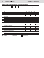
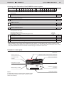
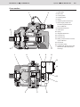
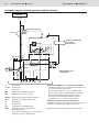
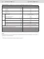
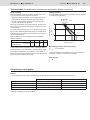
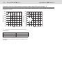
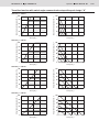
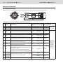
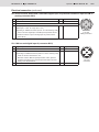
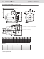
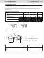
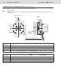
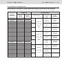
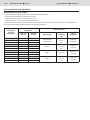
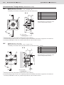
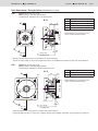
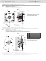
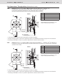
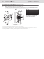
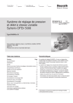
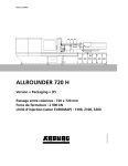
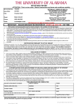
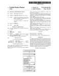
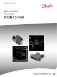
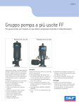
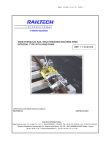
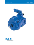
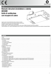
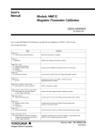
1
Variable-speed pressure and flow control system Sytronix DFEn 5000 1/26 RE 62242/12.11 Replaces: 30035, only Type SYHDFEn Type SYHDFEn-1X With axial piston variable displacement pump A4VSO Size 125 to 355 Component series 1X Maximum operating pressure 350 bar H7126/06 Table of contents Features ContentsPage An SYHDFEn-1X control system is used for the electro-hydraulic control of swivel angle, pressure and power/torque of an axial piston variable displacement pump. Features1 Ordering code 2 Cross section 5 Schematic diagram: Actuating system supplied internally 6 Technical data7 The control system consists of the following components: - A4VSO axial piston variable displacement pump optimized for the operation in the control system Transition function 10 - VT-DFPn-2X proportional valve as pilot valve with integrated electronics including inductive position transducer for valve position sensing Electrical connection 12 - Position transducer for sensing the swivel angle Closed-loop control quality9 Unit dimensions: SYHDFE.14 Through-drives: Torques 15 - Pressure transducer with suitable signal level and dynamics (separate order) Unit dimensions: Through-drive U9916 Accessories for through-drives 17 Unit dimensions: Through-drives19 Hubs for standard electric motor coupling 25 Project planning information 25 Installation information 25 More information about this control system 25 Information on available spare parts: www.boschrexroth.com/spc 2/26 Type SYHDFEn-1X RE 62242/12.11 Bosch Rexroth AG Hydraulics Ordering code: Pump of the Sytronix DFEn 5000 control system SYHDFEn-1X/ 125 R - V 1 1 2 3 4 5 6 7 8 9 2 3 4 Z 5 B 25 U99 - 0000 6 7 8 … 9 See following pages Series Control system with internal digital electronics, variable-speed, DFEn 5000 Size Displacement cm³ SYHDFEn-1X 125 125 180 180 250 250 355 355 Direction of rotation looking at the drive shaft Clockwise Counterclockwise ● ● ● ● ● ● ● ● R L Hydraulic fluid Mineral oil according to DIN 51524 (HL/HLP) HFC ● ● ● ● ● ● ● ● V F Drive shaft variant Cylindrical with key DIN 6885 Splined shaft profile DIN 5480 ● ● ● ● ● ● ● ● P Z Connection flange ISO 4-hole ● ● ● ● B ● ● ● ● 25 ● ● ● ● U99 ● ● ● ● ● ● ● ● 0000 0576 Connection for working lines Port B and S: SAE, laterally displaced by 90 °, metric mounting thread, 2nd pressure port B1 vis-à-vis B – upon delivery closed by means of flange plate Through-drive (see table page 17/18) Universal through-drive, convertible, without hub, without intermediate flange closed by means of cover Base pump variant Standard (internal pilot oil) External supply ● = available - = not available Preferred program RE 62242/12.11 Type SYHDFEn-1X Hydraulics Bosch Rexroth AG 3/26 Ordering code: Pilot valve of the SYHDFEn control system SYHDFEn-1X/ 125 R 1 10 11 12 13 2 3 - V 4 Z 5 B 25 U99 - 0000 - A 6 7 8 9 10 0 11 A 12 0 13 V - 14 * 15 Spool design Standard 4-groove spool (e.g. for HFC fluids) A C Valve installation orientation Integrated electronics parallel to the pump axis direction subplate 0 Additional functions Teach-in version for cyclic operation Real-time version (speed calculation without teach-in) A R Electronic assembly, options Standard 0 Actual pressure value input Parameter setting ex factory 14 15 Plug-in connector X1 X1 X1 X2 (description of the plug-in connectors on page 12/13) Current input 4...20 mA Voltage input 0...10 V Voltage input 1...10 V Voltage input 0.5...5 V 1) C V E F Further details in the plain text e.g. SO variant 1) With the SYDFEn control system with the additional function (feature 12 of the ordering code) "Teach-in version for cyclic operation" and with analog interfaces, the plug-in connector X2 cannot be used as actual pressure value input. Thus, a separate pressure transducer has to be used and connected to plug-in connector X1 in this case. Example of a name plate Word mark Material number, serial number underneath Material short text Date of manufacture Production order number Designation of origin Manufacturing number Plant Indication of direction of rotation Notice: For enquiries regarding the control system, material number, production order number, serial number, and date of manufacture are necessary. Production location 4/26 Bosch Rexroth AG Hydraulics Type SYHDFEn-1X RE 62242/12.11 Ordering code: Accessories Version 10/2011, enquire availability Accessories for Sytronix DFEn 5000 Mating connector 12-pin for central connection X1 without cable (assembly kit) Mating connector 12-pin for central connection X1 with cable set 2 x 5 m Mating connector 12-pin for central connection X1 with cable set 2 x 20 m Mating connector for interface X3, M12, straight, can be connected independently, 5-pin, shielded, A-coded, cable diameter 6...8 mm Pressure transducer HM 12-1X measurement range 315 bar (4...20 mA) Pressure transducer HM 13-1X measurement range 315 bar (0...10 V) Pressure transducer HM 17-1X measurement range 315 bar (4...20 mA) Pressure transducer HM 17-1X measurement range 315 bar (0.1...10 V) Test device VT-PDFE-1-1X/V0/0 Compact power supply unit VT-NE32-1X Converter USB/serial for laptops without serial interface VT-ZKO-USB/S-1-1X/V0/0 Cable for connecting a Win-PED PC (RS232) to the X2 interface length 3 m T connector for the simultaneous connection of a Win-PED PC (RS232) and a pressure transducer at plug-in connector X2 (only necessary with actual pressure value input 0.5...5 V (feature 14 = F) More accessories Hubs for through-drives Hubs for standard electric motor coupling Material number R900884671 R900032356 R900860399 Data sheet 08006 R901076910 R900199871 R900174374 R900773065 R900773124 R900757051 R900080049 R901066684 R901156928 R901117164 Page 18 25 29933 29933 30269 30269 29689-B 29929 RE 62242/12.11 Type SYHDFEn-1X Hydraulics Bosch Rexroth AG 5/26 Cross section 1 Swash plate 2 Pilot valve 3 Counter piston 4 Actuating piston 5 Spring 6 Inductive position transducer 7 Swivel angle position sensor with integrated electronics VT-SWA-LIN 8 Proportional solenoid 9 Valve spool 10 Spring 11 Integrated electronics 12 Connector X1 13 Connector X2 14 Mating connector X3 for connecting the CAN bus 15 Drive shaft 16 Connection flange 17 Subplate with through-drive U99, without hub, without intermediate flange 6/26 Type SYHDFEn-1X RE 62242/12.11 Bosch Rexroth AG Hydraulics Schematic diagram: Actuating system supplied internally Actuator Pressure transducer Optional Pilot valve VT-DFPn Signal exchange with the control (see page 12) Pump Swivel angle sensor VT-SWA-LIN... S Suction port K1, K2 Flushing port T Fluid drain MB Measuring port operating pressure MS Measuring port suction pressure M1, M2 Measuring port control chamber pressure R(L) Fluid filling + bleeding (leakage port) U Flushing port B Pressure port B1 2nd pressure port/additional port MB1 Measuring port operating pressure Size 250/355: G1/4 Size 125/180: Blind flange 1 ¼ ″ with pressure measuring port G1/4 attached to B1 When using the HM16-1X/...C13 pressure transducer: – Installation in MB (pump) in connection with electronic version "actual pressure value input F". – For attaching an HM16-1X/…C13, an adapter from M14x1.5 to G1/4 (Mat. no. R900695665) is necessary. – Due to the installation position, the HM16 cannot be used for all sizes without restrictions (replacement: HM17-1X/…-F… with extension cable). When using an external pressure transducer: Installation in the B line (preferably close to the actuator) and electrical connection via the central connector X1 Explanation in the operating instructions (see page 25) RE 62242/12.11 Type SYHDFEn-1X Hydraulics Bosch Rexroth AG 7/26 Technical data (For applications outside these parameters, please consult us!) mechanical and hydraulic Size / displacement Maximum speed Vg max [cm3] 1) n0 max Minimum speed [min-1] 125 180 1800 1800 qv0 max [l/min] 355 1800 1500 50 min-1 nmin Max. flow (displacement) 250 225 324 450 533 [l/min] 186 270 375 533 P0 max [kW] 131 189 263 311 [kW] 109 158 219 311 Tmax [Nm] 696 1002 1391 1976 TTotal [Nm] 1392 1400 2300 3557 TTotal [Nm] 1392 2004 2782 3952 TD [Nm] 696 1002 1391 1976 Fax max [N] 1000 1400 1800 2000 Fq [N] 1600 2000 2000 2200 Weight without filling quantity m [kg] 88 102 184 207 Moment of inertia around drive axis [kgm2] 0.03 0.055 0.0959 0.19 5 4 10 8 at max. speed with nE = 1500 min–1 Max. power (Δp = 350 bar) at max. speed with nE = 1500 min–1 Max. torque (Δp = 350 bar) Max. admissible drive torque Key Splined shaft Z overall torque Max. admissible through-drive torque Drive shaft load –Max. admissible axial force –Max. admissible radial force 2) Filling quantity, housing Maximum admissible operating pressure [l] 3) pmax Minimum operating pressure pmin Admissible inlet pressure p Hydraulic fluid temperature range ϑ Inlet pressure pabs [bar] → Maximum admissible degree of contamination of the hydraulic fluid according to ISO 4406 Speed n /n0max → 0.8…30 bar Mineral oil (HL, HLP) according to DIN 51524 HFC optional (see ordering code) Hydraulic fluid 350 bar ≥ 20 bar Displacement Vg /Vgmax → –20...+70 °C Class 18/16/13 (for particle size ≤ 4/6/14 μm) 1)The values are applicable at an absolute pressure of 1 bar in suction port S. With a reduction of the displacement or an increase in the inlet pressure, the speed can be increased according to the following characteristic curve. With a reduced inlet pressure, the speed is to be reduced. 2)In case of higher radial forces, please consult us. 3)When using HFC fluids, also see data sheet 92053. 8/26 Type SYHDFEn-1X RE 62242/12.11 Bosch Rexroth AG Hydraulics Technical data (For applications outside these parameters, please consult us!) electric Operating voltage UB Operating range (short-time operation) Upper limit Lower limit Current consumption (in static control operation) Rated current Maximum current Inputs 35 V UB(t)min 21 V IRated 0.6 A Imax U or I Analog current inputs, load RB Digital inputs ncommand / UOUT1 1) Outputs UB(t)max Actual pressure value input X1; pin 10 and 11 Analog voltage inputs αactual / UOUT2 2) Digital outputs RE 1.25 A Parameterizable: 0...20 mA; 4...20 mA; 0...10 V; 0…5 V; 0.5…5 V; 0.1...10 V; 1...10 V 100 Ω ≥ 100 kΩ Logic 0 ≤8V Logic 1 ≥ 14 V UA ±10 V 2 mA UA Imax ±10 V 2 mA Imax Logic 0 Logic 1 Ambient temperature range at the pump ϑ Storage temperature range (pump+electronics) ϑ Electronics design Ua < 1 V Ua ≥ UB – 5 V; 10 mA (short-circuit-proof) 0…50 °C 0…70 °C Integrated in the pilot valve (OBE) Electrical connection Protection class according to EN 60529 24 VDC +40 % –5 % See page 12 Pump incl. pilot valve Power limitation IP 65 with mounted and locked plug-in connectors Yes Notice: For information on the environment simulation testing for the areas of EMC (electromagnetic compatibility), climate and mechanical load, see data sheet 30030-U. 1, 2)The outputs are parameterizable, condition as supplied see page 12 RE 62242/12.11 Type SYHDFEn-1X Hydraulics Bosch Rexroth AG 9/26 Technical data (For applications outside these parameters, please consult us!) Bearing flushing Leakage pressure With the following operating conditions, flushing of the bearing is necessary for safe continuous operation: The admissible leakage pressure (housing pressure) depends on the speed (see diagram). – Applications with special fluids (not mineral fluids) due to limited lubricity and tight operating temperature range – Operation with boundary conditions of temperature and viscosity with mineral oil operation The bearing is flushed using port "U" in the area at the front flange of the variable displacement pump. The flushing fluid flows through the front bearing and exits with the pump leakage at the leakage port. For the individual sizes, the following flushing quantities are recommended: Size Recommended flushing quantity qSp [l/min] 125 180 250 355 5 7 10 15 The specified flushing quantities result in a pressure differential between port "U" (including fitting) and the leakage chamber of approx. 2 bar (series 1) and approx. 3 bar (series 3). When using the external bearing flushing, the throttle screw in port U has to be screwed-in to the stop. Leakage pressure pL abs [bar] → With vertical installation (drive shaft upwards), bearing flushing is recommended for lubricating the front bearing and the shaft seal ring. Size Speed n [min –1] → Max. leakage pressure (housing pressure) p L abs max = 4 bar absolute These specifications are guidelines; under special operating conditions, a limitation may become necessary. Flow direction S→B Closed-loop control quality Notices: – The specified values are only valid when using the system-related components specified in this data sheet. Swivel angle control Linearity tolerance ≤ 1.0 % Temperature error ≤ 0.5 % / 10 K Hysteresis Repeatability 1)Without considering the pump pulsation Pressure control 1) ≤ 1.5 % ≤ 0.5 % / 10 K Typically 0.3 % ≤ 0.2 % ≤ 0.2 % ≤ 0.2 % 10/26 Type SYHDFEn-1X RE 62242/12.11 Bosch Rexroth AG Hydraulics Transition function with pressure command value step with spool design "A" The specified curve shapes and control times refer to a drive speed of 1500 rpm and are only reached with an optimization of the pressure controller. Pressure p [bar] → Pressure p [bar] → pCommand pActual pActual pCommand Control time → T 95 % in ms with a connected hydraulic fluid volume (lines and actuators) Hydraulic fluid volume T95 % 5 – 10 l 200 ms 15 – 25 l 250 ms For pressures up to 40 bar, the values of the response times are larger. Control time → RE 62242/12.11 Type SYHDFEn-1X Hydraulics Bosch Rexroth AG Transition function with swivel angle command value step with spool design "A" Time [ms] → Actual swivel angle value [%] → Actual swivel angle value [%] → Size 125 p = 100 bar Time [ms] → Time [ms] → Time [ms] → Time [ms] → Time [ms] → Actual swivel angle value [%] → Actual swivel angle value [%] → Actual swivel angle value [%] → Actual swivel angle value [%] → Size 180 p = 100 bar Actual swivel angle value [%] → Size 250 p = 100 bar Actual swivel angle value [%] → Size 355 p = 100 bar Time [ms] → Time [ms] → 11/26 12/26 Type SYHDFEn-1X RE 62242/12.11 Bosch Rexroth AG Hydraulics Electrical connection X1:Central connection Mating connector according to EN 175201-804 (12-pin), ordering code see section Accessories on page 4 Assignment of connector or mating connector and cable set Pin Signal 1 2 +UB 0 V = L0 PE Earth Description Signal Assignment in the cable Type of signal direction set (accessories) Voltage supply IN Reference potential for the voltage supply - 2 Earthing connection for the electronics - Green/yellow 3 Fault Signals failures, e.g. cable break command / actual values, controller monitoring (logic 0 = error) OUT 4 M0 Reference potential for analog signals - 5 AI2 6 UOUT2 7 AI1 8 UOUT1 Analog input AI2 Standard: Swivel angle command value Analog output Standard: Actual swivel angle value normalized Analog input AI1 Standard: Pressure command value Analog output Standard: Speed command value 24 V DC Logic 24 V 1 DI1 Depending on additional function (feature 12 of the ordering code): – Teach-in version: Synchronization bit DI1 Yellow IN Analog ±10 V Green OUT Analog ±10 V Violet IN Analog 0...10 V Pink OUT Analog ±10 V Red IN Logic 24 V Brown Analog Black Analog Blue – Real-time version: Activate real-time operation Actual presIN sure value H Actual pressure value input: Signal level depends Actual pres- on feature 14 in the ordering code. 11 sure value L 10 n.c. 3 x 1.0 mm² White Digital input DI1 9 Supply line Gray Supply line 10 x 0.14 mm² shielded (one end of the shield must be connected to the control!) RE 62242/12.11 Type SYHDFEn-1X Hydraulics Bosch Rexroth AG 13/26 Electrical connection (continued) X2:Serial interface RS232 and a selectable digital input S1/pressure transducer input for HM 16 (mating connector M12) Pin Signal input 1 3 4 OUT, +UB Pin Signal RS232 2 RxD 5 TxD Reference L0 Analog input 0.5...5 V for HM 16 or digital input 0 V low, 10 V high (max. 12 V) Depending on additional function (feature 12 of the ordering code): Top view Mating connector – Teach-in version: Digital input "Variable-speed operation ON, S1" – Real-time version: Input as analog input for pressure transducer HM 16 X3:CAN bus and digital input 2 (connector M12) Pin Signal input Pin Signal CAN 1 n.c. 3 CAN GND 2 IN, digital IN2 (DI2) 4 CAN-HIGH Depending on additional function (feature 12 of the ordering code): – Teach-in version: Start teach-in, S2 – Real-time version: Manual speed provision active, speed is accepted according to the real-time operation status and the setting of the R parameters. Top view Connector 5 CAN-LOW 14/26 Type SYHDFEn-1X RE 62242/12.11 Bosch Rexroth AG Hydraulics Unit dimensions: SYHDFE. (dimensions in mm) The unit dimensions of the base pump (axial piston variable displacement pump A4VSO) are contained in data sheet 92050. Space required for removing the mating connector Connection X3 (CAN bus) Connection X2 (pressure transducer HM 16) Size A1 A2 A3 A4 A5 A6 A7 A8 A9 125 276 112.5 159 177 137 160 200 20 310 180 276 116 159 177 137 160 200 20 318 250 323 144 206 212 172 224 280 24 380 355 323 144 206 212 172 224 280 24 393 Shaft ends: Size Shaft Ø = P 1) = Z 2) 125 50 AS 14x9x80 W 50x2x30x24x9g 180 50 AS 14x9x80 W 50x2x30x24x9g 250 60 AS 18x11x100 W 60x2x30x28x9g 355 70 AS 20x12x100 W 70x3x30x22x9g 1)Cylindrical 2)Splined with key DIN 6885 shaft profile DIN 5480 RE 62242/12.11 Type SYHDFEn-1X Hydraulics Bosch Rexroth AG 15/26 Through-drives: Torques The control systems are supplied with universal through-drives U99. Their advantage is that the through-drive can be subsequently converted. By simply exchanging the intermediate flange and the hub, the through-drive can be adjusted to the on-site requirements. The assemblies as exchange kits can be ordered separately, see "Accessories for through-drives" on page 17 as well as data sheet 95581. Admissible drive and through-drive torques Size 125 180 250 355 TTotal max [Nm] 1392 2004 2782 3952 TD1 max [Nm] 696 1002 1391 1976 TD2 max [Nm] 696 1002 1391 1976 TD1 max [Nm] 696 1002 1391 1976 TD2 max [Nm] 696 1002 1391 1976 Splined shaft Maximally admissible total drive torque at the shaft of pump 1 (Pump 1 + Pump 2) A Admissible through-drive torque B Admissible through-drive torque Distribution of the torques Admissible inertial torque Related to connection flange of the main pump m1, m2 [kg] Weight of the pump l1, l2 [mm] Distance of the center of gravity Tm = m1 • l1 • 1 + m2 • l2 • 102 1 [Nm] 102 Size Admissible inertial torque Admissible inertial torque with dynamic mass acceleration of 10 g = 98.1 m/sec2 125 180 250 355 Tm adm. [Nm] 4200 4200 9300 9300 Tm adm. [Nm] 420 420 930 930 Weight (SYHDFE or A4VSO...DR) m [kg] 88 102 184 207 Distance of the center of gravity l1 [mm] 170 180 210 220 16/26 Type SYHDFEn-1X RE 62242/12.11 Bosch Rexroth AG Hydraulics Unit dimensions: Through-drive U99 (dimensions in mm) Before determining your construction, please request a binding installation drawing. U99 Size 125 to 355 with through-drive shaft, without hub, without intermediate flange, closed by means of a pressure-tight cover in a fluid-tight way Drawn without cover Only with size 250 and 355 Splined shaft profile DIN 5480 see table up to pump mounting face up to pump mounting face Size Main pump A1 A2 A4 A5 A6 49.7±1 M14; 15 deep 33.2+0.15 125 347 368 180 371 250 355 A9 A10 A12 A13 79.2+0.15 ø118H7 9 2.8+0.2 392 49.7±1 M14; 15 deep 33.2+0.15 M12; 18 deep – 79.2+0.15 ø118H7 9 2.8+0.2 431 455 61.4±1 M20; 22 deep 44.5+0.15 M10; 15 deep 58.15+0.15 86.2+0.15 ø160H7 9 2.8+0.2 460 487 61.4±1 9 2.8+0.2 M20; 22 deep A7 44.5+0.15 A8 M12; 18 deep – M10; 15 deep 58.15+0.15 86.2+0.15 Main pump A14 A15 A16 A17 A18 Splined shaft profile DIN 5480 125 ø121+0.1 ø70 46 22 – W35x1.25x26x9g 118 x 2 180 ø121+0.1 ø70 46 25 – W35x1.25x26x9g 118 x 2 250 ø163+0.1 30.5 86.2+0.15 W42x1.25x32x9g 160 x 2 355 ø163+0.1 34 86.2+0.15 W42x1.25x32x9g 160 x 2 Size ø87 ø87 64 64 1)O-ring ø160H7 for subsequent attachment (is also supplied) RE 62242/12.11 Type SYHDFEn-1X Hydraulics Bosch Rexroth AG 17/26 Accessories for through-drives Mounting kits for axial piston variable displacement pumps and SYHDFE control systems The order numbers for the combination of pumps are contained in the table shown below and in the data sheet 95581. Components Universal through-drive Main pump SYHDFE.-1X Size 125 Size 180 Size 250 Size 350 Mounting kit R902447035 R902447037 Flange kit R902446836 R902446850 Attachment pump Through-drive Size and type Centering Hub U52 82.55 mm Size 18 3/4 ″ Hub R902446823 R902446843 Mounting kit R902446996 R902446998 Flange kit R902446808 R902446809 Hub R902446824 R902446844 Mounting kit R902447001 R902447003 Flange kit R902446808 R902446809 Hub R902446825 R902446845 1″ Mounting kit R902447014 R902447016 UB8 Flange kit R902446816 R902446817 Hub R902446826 R902443227 Mounting kit R902447021 R902447022 Flange kit R902446818 R902446820 Hub R910943555 R910921237 Mounting kit R902447025 R902447026 Flange kit R902446818 R902446820 Hub R910904588 R902446849 Mounting kit R902447019 R902447020 Flange kit R902446816 R902446817 Hub R902446848 R902446830 Mounting kit R902447028 Flange kit R902446822 Hub R910902972 Mounting kit R902447029 Flange kit R902446822 Hub R910941327 SYDFE.-2X Size 28 A10VSO / BR31 Shaft S or R Size 45 7/8 ″ UB4 100 mm 160 mm Size 71 SYDFE.-3X Size 100 UB3 100 mm A10VSO / BR32 Shaft S or R Size 140 1¼″ UB9 180 mm 1½″ UB7 180 mm 1¾″ U34 Size 125 Size 180 Size 250 160 mm SYHDFE-1X A4VSO / BR30 Shaft Z Size 355 W 50x2x24x9g U35 224 mm W 60x2x28x9g U77 224 mm W 70x3x22x9g Flange designation SAE J744 82-1 (A-B) ISO 3019-2 100B2HW ISO 3019-2 100B2HW ISO 3019-2 160B4HW ISO 3019-2 180B4HW ISO 3019-2 180B4HW ISO 3019-2 160B4HW 18/26 Type SYHDFEn-1X RE 62242/12.11 Bosch Rexroth AG Hydraulics Accessories for through-drives Mounting kits for gear pumps To the attachment pumps listed in the table, the following conditions apply: – PGH with shaft R, flange U2, see data sheet 10223 – PGF3 with shaft J, flange U2, see data sheet 10213 – AZPF with shaft R, front cover R, see data sheet 10089 Also observe that the flange and the through-drive (see ordering code page 2 are identical. Check in the current data sheet of the gear pump whether the shaft ends have the specified dimensions. Components Universal through-drive Main pump SYHDFE.-1X Size 125 Size 180 Size 250 Size 350 Mounting kit R902447030 R902447032 Flange kit R902446836 R902446850 Hub R902446831 Mounting kit R902447040 R902447042 Flange kit R902446837 R902446851 Hub R902446824 R902446844 Mounting kit R902447045 R902447047 Flange kit R902446837 R902446851 Hub R902446825 R902446845 Mounting kit R902447052 R902447053 Flange kit R902446838 R902446852 Hub R910943555 R910921237 Attachment pump Through-drive Size and type Centering Hub PGF2, PGH2, PGH3, AZPF U01 82.55 5/8 ″ U 68 PGF 3 101.6 mm 7/8 ″ U04 PGH 4 101.6 mm 1″ U24 PGH 5 127 mm 1½″ Flange designation SAE J744 82-2(A-B) SAE J744 101-2(B) SAE J744 101-2(B) SAE J744 127-2(B) RE 62242/12.11 Type SYHDFEn-1X Hydraulics Bosch Rexroth AG 19/26 Unit dimensions: Through-drives (dimensions in mm) UB3 Flange ISO 3019-2 100, 2-hole Hub for splined shaft, 22-4 SAE B, 7/8 ″, 16/32 DP; 13T 3) for attaching an A10VSO 28/31 splined shaft S (see data sheet 92711) A1 A3 A4 A5 A6 2) 125 369 20.5 24.9 10 M12 180 393 20.5 24.9 10 M12 250 In preparation 355 In preparation Before determining your construction, please request a binding installation drawing. Size up to pump mounting face 1) 2 mounting screws and O-ring seal are included in the scope of delivery 2) Thread according to DIN 13, for the max. tightening torques, the installation information on page 25 is to be observed 3) According UB4 to ANSI B92.1a-1976, 30° pressure angle, flatt root, side fit, tolerance class 5 Flange ISO 3019-2 100, 2-hole Hub for splined shaft, 25-4 SAE B-B, 1 ″, 16/32 DP; 15T 3) for attaching an A10VSO 45/31 splined shaft S (see data sheet 92711) Size A1 A3 A4 A5 125 369 18.9 29.5 10 M12 180 393 18.9 29.5 10 M12 250 453 20.9 29.5 10 M12 355 482 20.9 29.5 10 M12 Before determining your construction, please request a binding installation drawing. 1)2 up to pump mounting face mounting screws and O-ring seal are included in the scope of delivery 2)Thread according to DIN 13, for the max. tightening torques, the installation information on page 25 is to be observed 3)According A6 2) to ANSI B92.1a-1976, 30° pressure angle, flatt root, side fit, tolerance class 5 20/26 Type SYHDFEn-1X RE 62242/12.11 Bosch Rexroth AG Hydraulics Unit dimensions: Through-drives (dimensions in mm) UB8 Flange ISO 3019-2 160, 4-hole Hub for splined shaft, 32-4 SAE C, 1 1/4 ″, 12/24 DP; 14T 3) for attaching an A10VSO 71/32 splined shaft S (see data sheet 92714) A1 A3 125 In preparation 180 In preparation 250 453 355 In preparation 20.9 A4 A5 A6 2) 38 9 M16 Before determining your construction, please request a binding installation drawing. Size up to pump mounting face 1)Mounting 2)Thread screws and O-ring seal are included in the scope of delivery according to DIN 13, for the max. tightening torques, the installation information on page 25 is to be observed 3)According UB7 to ANSI B92.1a-1976, 30° pressure angle, flatt root, side fit, tolerance class 5 Flange ISO 3019-2 180, 4-hole Hub for splined shaft, 44-4 SAE D, 1 3/4 ″, 8/16 DP; 13T 3) for attaching an A10VSO 140/31(32) splined shaft S (see data sheet 92711 (92714)) Size A1 A3 A4 A5 A6 2) 180 406 10.6 62 9 M16 250 453 10.6 64 9 M16 355 482 10.6 64 9 M16 Before determining your construction, please request a binding installation drawing. 1)Mounting 2) Thread up to pump mounting face screws and O-ring seal are included in the scope of delivery according to DIN 13, for the max. tightening torques, the installation information on page 25 is to be observed 3)According to ANSI B92.1a-1976, 30° pressure angle, flatt root, side fit, tolerance class 5 RE 62242/12.11 Type SYHDFEn-1X Hydraulics Bosch Rexroth AG 21/26 Unit dimensions: Through-drives (dimensions in mm) U34 Flange ISO 3019-2 160, 4-hole Hub according to DIN 5480 N50x2x24x8H for attaching an A4VSO/G 125 or 180 splined shaft Size A3 A4 A5 A6 2) 125 369 12.5 51.6 9 M16 180 393 12.5 51.6 9 M16 250 453 12.5 54 9 M16 355 482 12.5 54 9 M16 Before determining your construction, please request a binding installation drawing. A1 1) Mounting 2)Thread up to pump mounting face screws and O-ring seal are included in the scope of delivery according to DIN 13, for the max. tightening torques, the installation information on page 25 is to be observed U35 Flange ISO 3019-2 224, 4-hole Hub according to DIN 5480 N60x2x28x8H for attaching an A4VSO/G or A4CSG 250 splined shaft Size A1 A3 A4 A5 A6 2) 250 469 12.5 75 9 M20 355 498 12.5 75 9 M20 Before determining your construction, please request a binding installation drawing. 1)Mounting 2)Thread up to pump mounting face screws and O-ring seal are included in the scope of delivery according to DIN 13, for the max. tightening torques, the installation information on page 25 is to be observed 22/26 Type SYHDFEn-1X RE 62242/12.11 Bosch Rexroth AG Hydraulics Unit dimensions: Through-drives (dimensions in mm) U77 Flange ISO 3019-2 224, 4-hole Hub according to DIN 5480 N70x3x22x8H for attaching an A4VSO/G or A4CSG 355 splined shaft Size 355 Before determining your construction, please request a binding installation drawing. up to pump mounting face 1)Mounting 2)Thread U01 screws and O-ring seal are included in the scope of delivery according to DIN 13, for the max. tightening torques, the installation information on page 25 is to be observed Flange ISO 3019-1 82-2 (SAE A) Hub for splined shaft, 16-4 SAE A, 5/8 ″, 16/32 DP; 9T 3) for attaching an external gear pump AZ-PF-1X-004 ... 022 (see data sheet 10089) Rexroth recommends a special version of the gear pumps, please contact us Size A1 A3 A4 A5 A6 2) 125 369 16 19.4 13 M10 180 393 16 19.4 13 M10 250 453 16 19.4 13 M10 355 482 16 19.4 13 M10 Before determining your construction, please request a binding installation drawing. 1)2 up to pump mounting face mounting screws and O-ring seal are included in the scope of delivery 2)Thread according to DIN 13, for the max. tightening torques, the installation information on page 25 is to be observed 3)According to ANSI B92.1a-1976, 30° pressure angle, flatt root, side fit, tolerance class 5 RE 62242/12.11 Type SYHDFEn-1X Hydraulics Bosch Rexroth AG 23/26 Unit dimensions: Through-drives (dimensions in mm) U68 Flange ISO 3019-1 101-2 (SAE B), Hub for splined shaft 22-4 SAE B, 7/8 ″, 16/32 DP; 13T 3) for attaching an external gear pump AZ-PN-1X020...032 (see data sheet 10091 or an A10VO 28/31 and 52(53) splined shaft S (see data sheets 92701 and 92703) Rexroth recommends special versions of the gear pumps, please contact us A1 A3 A4 A5 A6 2) 125 369 28 25 13 M12 180 393 28 25 13 M12 250 453 19.5 23.1 13 M12 355 482 19.5 23.1 13 M12 Before determining your construction, please request a binding installation drawing. up to pump mounting face 1)2 Only with size 125 and 180 Size mounting screws and O-ring seal are included in the scope of delivery 2)Thread according to DIN 13, for the max. tightening torques, the installation information on page 25 is to be observed 3)According U04 to ANSI B92.1a-1976, 30° pressure angle, flatt root, side fit, tolerance class 5 Flange ISO 3019-1 101-2 (SAE B), hub for splined shaft 25-4 SAE B-B, 1 ″, 16/32 DP; 15T 3) for attaching an A10VO 45/31 and 52 (53) splined shaft S (see data sheets 92701 and 92703) or an internal gear pump PGH4 (see data sheet 10223) Size A3 A4 A5 1)2 Only with size 125 and 180 up to pump mounting face 125 369 18.9 29.4 13 M12 393 18.9 29.4 13 M12 250 453 18.9 29.4 13 M12 355 482 18.9 29.4 13 M12 Before determining your construction, please request a binding installation drawing. mounting screws and O-ring seal are included in the scope of delivery 2)Thread according to DIN 13, for the max. tightening torques, the installation information on page 25 is to be observed 3)According A6 2) 180 A1 to ANSI B92.1a-1976, 30° pressure angle, flatt root, side fit, tolerance class 5 24/26 Type SYHDFEn-1X RE 62242/12.11 Bosch Rexroth AG Hydraulics Unit dimensions: Through-drives (dimensions in mm) U24 Flange ISO 3019-1 127-2 (SAE C) Hub for splined shaft 38-4 SAE C-C, 1 1/2 ″, 12/24 DP; 17T 3) for attaching an A10VSO 100/31 splined shaft S (see data sheet 92701) or an A10VO 85/52(53) splined shaft S (see data sheet 92703) or an internal gear pump PGH5 (see data sheet 10223) A1 A3 A4 A5 A6 2) 125 369 10.4 50 13 M16 180 393 10.4 50 13 M16 250 453 12.4 55 13 M16 355 482 12.4 55 13 M16 Before determining your construction, please request a binding installation drawing. Size 1) 2 up to pump mounting face mounting screws and O-ring seal are included in the scope of delivery 2)Thread according to DIN 13, for the max. tightening torques, the installation information on page 25 is to be observed 3)According to ANSI B92.1a-1976, 30° pressure angle, flatt root, side fit, tolerance class 5 RE 62242/12.11 Type SYHDFEn-1X Hydraulics Bosch Rexroth AG 25/26 Hubs for standard electric motor coupling Motor SYHDFE.-1X Frame size/ Characteristic Shaft diameter 225/0 60 R900026055 250/0 65 R900026059 280/0 75 R900026063 R900714636 315/0 80 R901076760 R900088584 1) R9002109611) 315/1 80 R900026068 R900783295 R900210960 1)up Size 125/180 Size 100 Size 140 Shaft 50 mm Shaft 60 mm Shaft 70 mm to 40 °C Project planning information – Command values may only be switched via relays with gold contacts (low voltage, low currents). – Always shield command and actual value lines. Observe the notices in the instructions 30014-B, section 7.6. – The distance to aerial lines or radios must be at least 1 m. – Do not lay signal lines close to power cables. – Supplementary notices on the SYHDFEn control system can be found in the operating instructions (See section "More information about this control system" on this page). Installation information – Tightening torques: ∙The tightening torques specified in this data sheet are maximum values and must not be exceeded (maximum values for screw-in threads). Manufacturer‘s specifications on the max. admissible tightening torques of the fittings used are to be observed! ∙For mounting screws according to DIN 13, we recommend checking the tightening torque case by case according to VDI 2230 version 2003. More information about this control system Operating instructions for SY(H)DFEn 30014-B User manual CANopen interface for SY(H)DFEn 30014-02-Z Data sheet for universal through-drive for connecting two pumps into one combination 95581 Data sheet for axial piston variable displacement pump A4VSO 92050 Data sheet for axial piston variable displacement pump A4VSO for HFC 92053 Data sheet for pilot valve VT-DFP.-2X 29016 Data sheet for swivel angle sensor VT-SWA-LIN-1X 30263 Data sheet for pressure transducer HM 12-1X and HM 13-1X 29933 Data sheet for pressure transducer HM 16-1X 30266 Data sheet for pressure transducer HM 17-1X 30269 Operating instructions for test device VT-PDFE 29689-B Current information is also available on the Internet at the address http://www.boschrexroth.com/sydfe (English) or http://www.boschrexroth.de/sydfe (German). 26/26 Bosch Rexroth AG Hydraulics Type SYHDFEn-1X RE 62242/12.11 Notes Bosch Rexroth AG Hydraulics Zum Eisengießer 1 97816 Lohr am Main, Germany Phone +49 (0) 93 52 / 18-0 Fax +49 (0) 93 52 / 18-23 58 [email protected] www.boschrexroth.de © This document, as well as the data, specifications and other information set forth in it, are the exclusive property of Bosch Rexroth AG. It may not be reproduced or given to third parties without its consent. The data specified above only serve to describe the product. No statements concerning a certain condition or suitability for a certain application can be derived from our information. The information given does not release the user from the obligation of own judgment and verification. It must be remembered that our products are subject to a natural process of wear and aging. RE 62242/12.11 Type SYHDFEn-1X Hydraulics Bosch Rexroth AG 27/26 Notes Bosch Rexroth AG Hydraulics Zum Eisengießer 1 97816 Lohr am Main, Germany Phone +49 (0) 93 52 / 18-0 Fax +49 (0) 93 52 / 18-23 58 [email protected] www.boschrexroth.de © This document, as well as the data, specifications and other information set forth in it, are the exclusive property of Bosch Rexroth AG. It may not be reproduced or given to third parties without its consent. The data specified above only serve to describe the product. No statements concerning a certain condition or suitability for a certain application can be derived from our information. The information given does not release the user from the obligation of own judgment and verification. It must be remembered that our products are subject to a natural process of wear and aging. 28/26 Bosch Rexroth AG Hydraulics Type SYHDFEn-1X RE 62242/12.11 Notes Bosch Rexroth AG Hydraulics Zum Eisengießer 1 97816 Lohr am Main, Germany Phone +49 (0) 93 52 / 18-0 Fax +49 (0) 93 52 / 18-23 58 [email protected] www.boschrexroth.de © This document, as well as the data, specifications and other information set forth in it, are the exclusive property of Bosch Rexroth AG. It may not be reproduced or given to third parties without its consent. The data specified above only serve to describe the product. No statements concerning a certain condition or suitability for a certain application can be derived from our information. The information given does not release the user from the obligation of own judgment and verification. It must be remembered that our products are subject to a natural process of wear and aging.