1
Rexroth NYCe4000 Multi-axis motion control system Tools Manual 2009-09 Title Rexroth NYCe4000 Tools Manual Type of documentation Document Typecode Internal File Reference Purpose of Documentation Record of revisions List of trademarks User Manual 59.1.6 This document describes the functions of the software tools included in the Rexroth NYCe4000. Description Release date Notes Product release 1.4 04.2007 First issue Product release 2.0 09.2007 Second issue Product release 2.1 10.2008 NYCeInspector Product release 2.2 02.2009 IndraDrive support Product release 2.2.1 09.2009 IndraDrive motors without encoder flash memory, NY4111 support FireWire is a registered trademark of Apple® Computer Inc. Microsoft®, Windows XP® are either registered trademarks or trademarks of Microsoft ® Corporation in the United States and/or other countries. Products in this publication are referred to by their general trade names. In most, if not all cases, these designations are claimed as trademarks or registered trademarks of their respective companies. Copyright © Bosch Rexroth AG 2007 Copying this document, giving it to others and the use or communication of the contents thereof without express authority, are forbidden. Offenders are liable for the payment of damages. All rights are reserved in the event of the grant of a patent or the registration of a utility model or design (DIN 34-1). Validity Published by The specified data is for product description purposes only and may not be deemed to be guaranteed unless expressly confirmed in the contract. All rights are reserved with respect to the content of this documentation and the availability of the product. Bosch Rexroth AG Luchthavenweg 20 ● 5657 EB Eindhoven ● The Netherlands Telephone +31 (0)40 2578888 ● Fax +31 (0)40 2578800 http://www.boschrexroth.com/nyce NYCe4000 Tools Manual Bosch Rexroth AG 3/136 Introduction Contents 1 2 3 4 5 6 7 Introduction.................................................................................................... 5 1.1 General remark on XML formatted files.............................................. 5 1.2 Used abbreviations in this manual ..................................................... 5 Getting started ............................................................................................... 7 2.1 First time start-up of the NYCe4000 System ...................................... 7 2.2 Configuring versus tuning: parameter handling................................ 13 2.3 Define an axis .................................................................................. 14 2.4 Quick start ........................................................................................ 20 NYCeConfigurator ....................................................................................... 35 3.1 Parameter handling .......................................................................... 36 3.2 Save and restore settings................................................................. 36 3.3 Configuration at the node level......................................................... 38 3.4 Configuration at the MCU level ........................................................ 40 3.5 Configuration at the drive module level ............................................ 41 3.6 Configuration at the axis level .......................................................... 51 NYCeTuner ................................................................................................. 61 4.1 Introduction ...................................................................................... 61 4.2 Overview .......................................................................................... 61 4.3 Select and initialize an axis .............................................................. 62 4.4 Saving and shutting down ................................................................ 62 4.5 Expert mode..................................................................................... 63 4.6 Standard controller parameters........................................................ 66 4.7 Enhanced controller parameters ...................................................... 69 4.8 Control filter parameters................................................................... 75 4.9 Current control parameters (not for NY4130 / NY4170) ................... 80 4.10 Stepper control parameters.............................................................. 81 4.11 Alignment parameters (BLAC and IndraBLAC only) ........................ 83 4.12 Miscellaneous NYCeTuner parameters............................................ 89 4.13 Controller settling criteria.................................................................. 90 4.14 AutoTweak tool ................................................................................ 93 4.15 NYCeTuner motion options .............................................................. 94 4.16 Axis tuning in “expert” mode........................................................... 100 NYCeScope............................................................................................... 110 5.1 Trace channel selection ................................................................. 110 5.2 Trace setup .................................................................................... 112 5.3 Trace display manipulation............................................................. 114 5.4 Trace states ................................................................................... 118 NYCeInspector .......................................................................................... 120 6.1 Introduction .................................................................................... 120 6.2 Overview ........................................................................................ 120 6.3 Inspecting at node level.................................................................. 121 6.4 Inspecting at drive level.................................................................. 122 6.5 Inspecting at axis level ................................................................... 123 NYCeCommand ........................................................................................ 127 4/136 Bosch Rexroth AG NYCe4000 Tools Manual Introduction 8 NYCeLogger .............................................................................................. 131 9 NYCeWatch ............................................................................................... 133 10 NYCeNetMonitor........................................................................................ 135 NYCe4000 Tools Manual Bosch Rexroth AG 5/136 Introduction 1 Introduction The NYCe4000 Tools Manual provides information about the possibilities and functions of the software tools included with the NYCe4000 software. The following tools are described in this manual: NYCeConfigurator (chapter 3) NYCeTuner (chapter 4) NYCeScope (chapter 5) NYCeInspector (chapter 6) NYCeCommand (chapter 7) NYCeLogger (chapter 8) NYCeWatch (chapter 9) NYCeNetMonitor (chapter 10) The Sequencer and Simulation tools are described in separate manuals, NYCe4000 Sequencer User Manual and NYCe4000 Simulation User Manual. A Getting Started chapter has been included for first time users of the NYCe4000 system besides the functional descriptions of the tools. The dialog screens shown in this manual may slightly differ from the actual displayed windows on the screen. Attention: You must have “administrator” rights on the PC you run the NYCe4000 tools. If you are logged on with insufficient rights, the error NCS_ERR_SYSTEM_ERROR appears. 1.1 General remark on XML formatted files The NYCe4000 tools and software API functions can read and write XML formatted files on the host. You can also modify these XML (configuration) files with a suitable (XML) editor. If you do not use the NYCe4000 tools, but use an external editor to modify an XML formatted file, make sure that the file is saved ANSI encoded. If the file is saved with a byte order mask (for example a UTF-8 byte order mask), the NYCe4000 tools and API functions report the error SAC_ERR_OPEN_FILE_ERROR when such a file is opened. 1.2 Used abbreviations in this manual The following table gives a summary of abbreviations used in this manual. 6/136 Bosch Rexroth AG NYCe4000 Tools Manual Introduction Table 1 Summary of used abbreviations Abbreviation Description BLAC Brushless AC motor BLDC Brushless DC motor cout Controller out unit (user-defined dimension of controller out) FFT Fast Fourier Transformation FRF Frequency Response Function IEEE Institute of Electrical and Electronics Engineers MCU Motion Control Unit NHI Node Hardware Interface (subsystem) NY4110 Motion Control Unit (MCU) NY4111 MCU with Cat-5 interface NY4120 PWM Drive Module NY4130 DC Drive Module NY4140 High Voltage Drive Module NY4150 SERCOSIII Master Module NY4170 High Voltage Piezo Drive Module pu Position unit (user-defined dimension of position) PVL Position Velocity Loop PWM Pulse Width Modulation SAC Single Axis Control (subsystem) UDC User Definable Control NYCe4000 Tools Manual Bosch Rexroth AG 7/136 Getting started 2 Getting started This chapter describes how to get started with the NYCe4000 system, using a basic way to get an axis operational with the NYCe4000 tools. You can use this chapter as an introduction to the NYCe4000 tools. The axis will be configured with revolutions as the dimension unit for the position and amperes as the dimension unit for the controller out. The axis must be driven by the appropriate drive module in this “getting started” example. When you use this walkthrough, you must have a NYCe4000 system ready for use with a DC motor, a brushless DC (BLDC) or a brushless AC (BLAC) rotary motor, a piezo motor, a stepper motor, sensing stepper motor (stepper motor with a position encoder), or an IndraDrive-based motor connected to the first axis of the first drive. The motor must be equipped with an S0/S90 encoder, if applicable. Consult the NYCe4000 Hardware System Manual and NYCe4000 Standard Housings and Accessories Manual for more information about the hardware setup of the NYCe4000 system. The NYCe4000 software must be installed on the computer. Attention: For safety reasons, disconnect the motor from the system until you use the NYCeTuner in this walkthrough. The encoder can always be connected. 2.1 First time start-up of the NYCe4000 System When you start the NYCe4000 node for the first time, you must initialize the Motion Control Unit (MCU, NY4110 or NY4111) with the bootloader, the gateware for the installed drive modules and the firmware for the MCU. You can do the initialization with the NYCeConfigurator or the NYCeCommand tool of the NYCe4000 software package. NYCeConfigurator has a graphical user interface and is best suited for interactive use. NYCeCommand offers command-line style entry of NYCe4000 command and is best suited for command scripts. Initialization with NYCeConfigurator Switch on the 24V System power supply to the NYCe4000 system (only the MCU needs to be active) and start the NYCeConfigurator tool. Do the following steps in the described order. 1. Select a specific node icon in the tree shown in the pane at the left side to download the required files to that selected node only. 2. Click the “Save / Download” tab in the pane at the right side, see Fig. 1. 8/136 Bosch Rexroth AG NYCe4000 Tools Manual Getting started Fig. 1 Download the required files to a specific node 3. Click the “Bootloader” button on the “Save / Download” tab in the “Download” section. The “Download Bootloader to Node” dialog box appears. 4. Browse to the “upgrade” folder in the folder that you specified during the installation of the NYCe4000 software. The default path used during the NYCe4000 software installation is C:\Program Files\Rexroth\NYCe4000. Select the bootloader file “boot4110_4111.bin” and click the “Open” button, see Fig. 2. A progress message box is displayed during the download action. Fig. 2 Browse to the location of the bootloader file and select the bootloader file NYCe4000 Tools Manual Bosch Rexroth AG 9/136 Getting started 5. Select “Flash bank 0” in the “Gateware” section. You must start the download of gateware files into bank 0, and you must fill the banks consecutively, that is, you can not skip a bank. You can download up to 3 different gateware files, as described in the next two steps. 6. Click the “Gateware” button in the “Gateware” section. The “Download Gateware to Node” dialog box appears, see Fig. 3. 7. Select from the “upgrade” folder the appropriate gateware “.bit” file. You must download the gateware file of each drive module installed in the node. The names of the gateware files are self-explaining, that is, they include the drive module identification number (see Table 2). Click the “Open” button. A progress message box is displayed during the download action. Fig. 3 Select the appropriate gateware file(s) 8. Repeat the previous 2 steps for all drive module types installed in the node. Make sure to select the consecutive next flash bank in the “Gateware” section. 9. Click the “Firmware” button in the “Download” section. The “Download Firmware to Node” dialog box appears, see Fig. 4. Fig. 4 Select the firmware file 10/136 Bosch Rexroth AG NYCe4000 Tools Manual Getting started 10. Select the firmware file “firmware4110_4111.sys” from the “upgrade” folder and click the “Open” button. A progress message box is displayed during the download action. When the download of the firmware is finished, you are asked to restart the node. You must restart the node to start the (new) downloaded firmware. If the NYCe4000 system includes the NY4150 module, you must download the microware and the SERCON gateware, after the MCU is restarted. Note that you must have downloaded the gateware of the NY4150 in step 6 and 7 else the download tab will not be available. Do the following steps to configure the NY4150 SERCOSIII Master module. 1. Select the NY4150 module icon of the specific node in the tree shown in the pane at the left side, and click the “Download” tab in the pane at the right side. See Fig. 5. Fig. 5 Download tab specific for the NY4150 SERCOSIII Master module 2. Click the “Download SERCON Gateware” button in the “SERCON Gateware” section. The “Download SERCON Gateware to DRV 0.0: NY4150” dialog box appears. 3. Select the SERCON gateware file “sercon100m.sgw” from the “upgrade” folder and click the “Open” button. A progress message box is displayed during the download action. 4. Click the “Download Microware” button in the “Microware” section. The “Download Microware to DRV 0.0: NY4150” dialog box appears. The numbers in the title caption “DRV 0.0” depend on the node number and the I/O slot number (always 0) in which the NY4150 module is installed. 5. Select the microware file “microware4khz.mcr” from the “upgrade” folder and click the “Open” button. A progress message box is displayed during the download action. When the download of the microware is finished, you are asked to restart the node. You must restart the node to start the (new) downloaded microware. NYCe4000 Tools Manual Bosch Rexroth AG 11/136 Getting started You can also select the “NYCe4000 System” icon in the pane at the left side and right-click the icon to download the required files to all nodes in the system. A popup menu appears, see Fig. 6. Fig. 6 The menu options at the System level After the selection of an entry in the popup menu, the specific dialog box appears as described before, and you can select the file that must be downloaded. If the system contains an NY4150 SERCOSIII Master module, you must use the described steps 1 to 5 of the previous paragraph to download the SERCON gateware and microware. Initialization with NYCeCommand Switch on the 24V System power supply to the NYCe4000 system (only the MCU needs to be active) and start the NYCeCommand tool. Enter the following commands in this order: 1. DwnDownloadPrimaryBoot [NodeNr] [PATH]\boot4110_4111.bin Note: DwnDownloadPrimaryBoot must be used with care: when the download is interrupted or aborted, the MCU will become unusable. 2. DwnEraseGateware [NodeNr] After the gateware banks are erased, you can download the new gateware files. Which gateware files you download to the MCU depends on the installed drive modules. You must fill the gateware banks starting with bank 0, and you must fill the banks consecutively, that is, you can not skip a bank. Table 2 shows the names of the gateware files that must be downloaded when the specified drive module is installed. You can download up to 3 different gateware files. Table 2 Drive module and its gateware file name Drive module Gateware file name NY4120 drivefpga_4120_encoders.bit NY4130 drivefpga_4130.bit NY4140 drivefpga_4140_encoders.bit NY4150 drivefpga_4150.bit NY4170 drivefpga_4170.bit 12/136 Bosch Rexroth AG NYCe4000 Tools Manual Getting started For example, when the NYCe4000 system has NY4120, NY4130 and NY4140 drive modules installed you enter the following commands. 3. DwnDownloadGateware [NodeNr] 0 [PATH]\drivefpga_4120_encoders.bit 4. DwnDownloadGateware [NodeNr] 1 [PATH]\drivefpga_4130.bit 5. DwnDownloadGateware [NodeNr] 2 [PATH]\drivefpga_4140_encoders.bit The last download command downloads the firmware. 6. DwnDownloadFirmware [NodeNr] [PATH]\firmware4110_4111.sys Notes: - All commands are case sensitive. - [NodeNr] is the number of the node in the FireWire network. The first node, most close connected to the computer) usually has node number 0. - [PATH] is the location of the .bit, .bin and .sys files. If you installed the NYCe4000 software in the default installation folder, [PATH] is “C:\Program Files\Rexroth\NYCe4000\upgrade”. - If you use a new NYCe4000 software release, you may have to update the gateware, the bootloader and firmware. Always check the Release Bulletin that is included on the CD-ROM before you use the software tools. You can also use the initialization procedure described above to upgrade the NYCe4000 system. You must reset the MCU after you entered the commands described in steps 1 to 6. Do the following steps to reset the MCU. 7. Switch off the 24V System supply voltage. 8. Wait 5 seconds. 9. Switch on the 24V System supply voltage. If the NYCe4000 system includes the NY4150 module, you must download the microware and the SERCON gateware, after the NYCe4000 is restarted. Note that you must have downloaded the gateware of the NY4150 in step 3, 4 or 5, else you can not download the microware and the SERCON gateware. Do the following steps to configure the NY4150 SERCOSIII Master module. 10. DwnDownloadSerconGateware 0 [PATH]\sercon100m.sgw 11. DwnDownloadMicroware 0 [PATH]\microware4khz.mcr 12. Switch off the 24V System supply voltage. 13. Wait 5 seconds. 14. Switch on the 24V System supply voltage. The MCU is now ready for use. Note: Every factory new MCU has the same name (NY4110_node or NY4111_node). If you build a multi-node network with these new MCU modules, the duplicate node name error is reported. You can solve this problem with the NYCeConfigurator tool, or via the SysSetNodeName function after you downloaded the bootloader, gateware file(s) and firmware to all MCU's and reset the MCU's. Another option to solve the problem is the removal of the MCU's with the duplicate node names from the network. Note that the MCU will also revert to the factory default name when the flash memory is downgraded. NYCe4000 Tools Manual Bosch Rexroth AG 13/136 Getting started 2.2 Configuring versus tuning: parameter handling You can change parameters in the NYCe4000 system with the NYCeConfigurator and the NYCeTuner tool. The NYCeConfigurator is used for setting parameters that are fixed for a certain configuration. These parameters, for example motor and sensor type, only need to be set once. The NYCeTuner is used for setting parameters during optimizing the axis behavior, for example the gain of the position loop. These parameters are changed by the user during the process optimization. Parameter handling is different between the NYCeConfigurator and the NYCeTuner for this reason. Compare the two figures below. If you change a parameter in the NYCeConfigurator, the change is only applied in the NYCeConfigurator itself and not in the node. Only after you click the “Apply” or “OK” button, the new parameter value(s) are sent to the node. When you enter a value in the NYCeTuner, that value is directly sent to the node. PC NYCeConfigurator XML file set a value “Apply” or “OK” “Save to file” NODE flash “Save to flash” Fig. 7 PC Parameter handling using NYCeConfigurator NYCeTuner XML file set a value “Save to file” NODE flash “Save to flash” Fig. 8 Parameter handling using NYCeTuner To apply certain configuration settings, the NYCeConfigurator requests for an axis shutdown. To be able to use the applied settings after a (re-)initialize, you must first save the settings to a file or flash memory after the shutdown of the axis is done. 14/136 Bosch Rexroth AG NYCe4000 Tools Manual Getting started 2.3 Define an axis The procedure to get a motor operational with the NYCe4000 system basically consists of 3 steps: 1. Create an axis with the NYCeConfigurator tool. 2. Configure the axis with the NYCeConfigurator tool. The steps to configure a stepper motor axis or an IndraDrive controlled motor are different from the steps to configure a DC, BLAC, BLDC or piezo motor. For this reason the steps for the configuration of a stepper motor or sensing stepper motor and the steps for the configuration of an IndraDrive controlled motor are separately described. 3. Tune the axis with the NYCeTuner tool. In this chapter an axis is created and configured. The chapter “Quick start” helps you to get an axis initially operational. For optimal performance of an axis, the NYCe4000 software provides additional tools, like the NYCeTuner and NYCeScope tool, which offer much more functionality to tune an axis. Note: When you use the NYCeConfigurator, always click the “Apply” button before you select another tree item (node, drive, axis, IndraDrive) otherwise any change that you made is not applied. Create an axis Start the NYCeConfigurator to create a new axis. Do the following steps to create the new axis. 1. Click on the “DRV 0.0” element in the NYCe4000 system tree, displayed in the pane at the left side of the NYCeConfigurator, see Fig. 9. 2. Click the “New” button in the pane at the right side. A new axis named DEF_AXIS_1 is created and displayed in the NYCe4000 system tree as a child of “DRV 0.0”. Fig. 9 NYCeConfigurator window NYCe4000 Tools Manual Bosch Rexroth AG 15/136 Getting started Configure the axis for a DC, BLAC, BLDC or piezo motor Click on the “DEF_AXIS_1” axis in the pane at the left side of the NYCeConfigurator. You can change the name of the axis in the “General” tab, see Fig. 10. The axis is renamed to ‘MyAxis’ in this walkthrough. Fig. 10 New axis selected in the NYCeConfigurator Do the following steps in the “General” tab to setup a rotational axis with revolution as axis position unit. 1. Set the “Axis Type” to Servo, if this field shows another selection. 2. Select the “Motor Type”, the listed motor types depend on the chosen drive module. The types available are DC Brushed, AC Brushless, DC Brushless, Stepper, Sensing Stepper, or Piezo stack. The motor type IndraBLAC is only available with the NY4150 SERCOSIII Master module. 3. Set the “Axis Resolution” equal to the encoder resolution. Example: If the encoder connected to the motor shaft has a quadrature 512 cycles per revolution (CPR) output, then the resolution of the encoder must be set to 2048 increments per revolution. This is also known as the Pulses Per Revolution of an encoder (PPR). 4. Set axis unit “Increments” to “revolutions”. 5. Set the “Controller Output Resolution” equal to the maximum drive current or voltage that the drive module can generate. “Controller Output Resolution” is a scale factor of the controller output. Internally, the controller output uses a range of -1.0 … +1.0. With the “Controller Output Resolution” you can scale this range to any other range, see also chapter 3.6. For the NY4120 and NY4140 the value is 20.0, for the NY4130 the value is 24.0 and for the NY4170 the value is 135.0. For safety reasons a very high value is set as the default value. 6. Click the “Frequencies” tab. 16/136 Bosch Rexroth AG NYCe4000 Tools Manual Getting started 7. Set the frequencies as shown in see Fig. 11. For the NY4130 and NY4170 drive module only the “Setpoint (Node) Frequency” and “Position Velocity Loop Frequency” are available. Fig. 11 Axis frequency settings 8. If you selected a BLAC or BLDC motor in step 2, there is also a tab called “Commutation”. Click the “Commutation” tab. - For a BLAC motor, get the number of pole pairs from the motor manufacturer datasheet and set the “Pos units / Total nr. of Pole Pairs” to 1, as the position unit has been set to revolutions. - For a BLDC motor, select the Hall sensor input type (DIGIN or RS422), and get the commutation table from the manufacturer datasheet. If the commutation table is unknown, you can use the initial table shown by the NYCeConfigurator. 9. Click the “Motor” tab. 10. Set Saturation level of the axis equal to the peak current of the motor if you use an NY4120 drive module. If you use an NY4130 or NY4170 drive module, the saturation level is the maximum voltage for the controller output of the drive module. 11. Click the “Safety” tab. 12. Set quick stop acceleration (rev/s) equal to 10x the nominal speed. 13. Set smooth stop acceleration (rev/s2) equal to 10x the nominal speed. 14. Set smooth stop jerk (rev/s3) equal to 100x the nominal speed. 15. Set maximum servo bus voltage “High pos” to 120% of the nominal voltage. 16. Set minimum servo bus voltage “Low pos” to 80% of the nominal voltage. 17. Click the “Apply” button. 18. Click the “Save / Download” tab. 19. Save the motor settings to a file, for example “MyAxis.xml”. NYCe4000 Tools Manual Bosch Rexroth AG 17/136 Getting started Configure the axis for a stepper motor or sensing stepper motor Click on the “DEF_AXIS_1” axis in the pane at the left side of the NYCeConfigurator. You can change the name of the axis in the “General” tab. The axis is renamed to ‘MyAxis’ in this walkthrough. Note that the position encoder of a sensing stepper motor is not used by the control loop. It can only be used to read the actual axis position. Do the following steps in the “General” tab to setup a rotational axis with revolution as axis position unit. 1. Set the “Axis Type” to “Stepper” or “Sensing Stepper”. If you select “Sensing Stepper”, you must also define the used position interface. 2. Set the “Axis Resolution” equal to the number of (full) steps per revolution of the stepper motor (consult the motor manual). 3. Set axis unit “Increments” to “revolutions”. 4. Set the “Controller Output Resolution” equal to the maximum drive current that the NY4120 drive module can generate. The maximum drive current is 20A. The “Controller Output Resolution” is a scale factor of the controller output. Internally, the controller output uses a range of -1.0 … +1.0. With the “Controller Output Resolution” you can scale this range to any other range. For example, if “Controller Output Resolution” is set to 20.0, the controller output value can be seen as a value between -20.0 … +20.0 which matches the output current. For safety reasons a very high value is set as default. 5. Click the “Commutation” tab. 6. Set the number of micro-steps per step equal to 1. 7. Click the “Motor” tab. 8. Set the saturation level equal to the rated current of the stepper motor (consult the motor manual). 9. Click the “Safety” tab. 10. Set the following fields: - Quick stop acceleration equal to 20. Smooth stop acceleration equal to 20. Smooth stop jerk equal to -1 (disables the jerk for the smooth stop). Nominal servo bus voltage equal to the voltage applied to the drive. Maximum servo bus voltage “High pos” to 120% of the nominal voltage. Minimum servo bus voltage “Low pos” to 80% of the nominal voltage. 11. Click the “Apply” button. 12. Click the “Save / Download” tab. 13. Save the motor settings to a file, for example “MyAxis.xml”. Configure the axis for an IndraDrive controlled motor The NYCeConfigurator displays the configuration with the NY4150 in the pane at the left hand side. Click on the “IndraDrive 1” axis in the pane at the left side of the NYCeConfigurator. The number “1” is the unit number which is the same as the SERCOS address of the IndraDrive. The SERCOS address can be any number from 1 to 99 (inclusive). You can change the SERCOS address through the panel on the IndraDrive C. Changing the SERCOS address through the NYCe4000 software or NYCe4000 tools is not supported. Notes: 1. The SERCOS address must be unique in the SERCOS network. 2. If you change the SERCOS address on an IndraDrive, you must initialize the SERCOS network again to force an update of the administration in the node and the host. 3. If the SERCOS network was broken (for example by disconnecting and reconnecting a SERCOS network cable or resetting an IndraDrive in the 18/136 Bosch Rexroth AG NYCe4000 Tools Manual Getting started SERCOS network), the SERCOS network will not start if not all axes on all IndraDrives in this SERCOS network are shut down first, because of safety requirements. You can change the name of the axis in the “General” tab, see Fig. 12. The axis is renamed to ‘MyAxis’ in this walkthrough. Fig. 12 New IndraDrive “MyAxis” selected in the NYCeConfigurator The fields “Axis Type”, “Motor Type” and “Position interface” are predefined with an IndraDrive, and can not be changed. Do the following steps in the “General” tab to setup a rotational axis with revolution as axis position unit. See Fig. 12 for typical values. 1. Set the “Axis Resolution”. The resolution is 10-4 degrees for a rotary motor and 10-4 mm for a linear motor on an IndraDrive. 2. Set axis unit “Increments” to “revolutions”. 3. Set the “Controller Output Resolution” to the specified peak current of the type of IndraDrive connected to the NY4150. Note that IndraDrives specify the nominal current, not the peak current. The “Controller Output Resolution” is a scale factor of the controller output. Internally, the controller output uses a range of -1.0 … +1.0. With the “Controller Output Resolution” you can scale this range to any other range. 4. Click the “Motor” tab. 5. Set “Saturation Level [Cout]” of the axis equal to the peak current of the motor. This is the same value that you entered in the “General” tab in “Controller Output Resolution” field. 6. Click the “Safety” tab. NYCe4000 Tools Manual Bosch Rexroth AG 19/136 Getting started Fig. 13 Axis safety settings 7. Set the quick stop acceleration (rev/s2) equal to 10x the nominal speed. 8. Set the smooth stop acceleration (rev/s2) equal to 10x the nominal speed. 9. Set the smooth stop jerk (rev/s3) equal to 100x the nominal speed. 10. Click the “Apply” button. - The entered values may change. This is caused by the arithmetic used to convert the value to a parameter value sent to the IndraDrive. - NYCeConfigurator may display a warning message, because several parameters are set automatically to correct default values. Click the “OK” button. Fig. 14 NYCeConfigurator warning message 11. Click the “Save / Download” tab. 12. Save the motor settings to a file, for example “MyAxis.xml”. 20/136 Bosch Rexroth AG NYCe4000 Tools Manual Getting started 2.4 Quick start This chapter describes the steps to get an operational axis with a motor using the NYCeTuner. The NYCeTuner has a so-called “wizard” mode that guides you through the configuration of a servo based axis. The wizard shows, graphically supported, the procedure step by step by going through the tabs of the NYCeTuner from left to right. It is important that you follow the described sequence. The flow diagram in Fig. 15 shows the steps you must do to get an axis of each type of motor operational. The names of the steps in the flow diagram are identical to the tabs of the NYCeTuner. The “wizard” mode is not yet supported for the IndraDrive. See the end of this chapter for a short description to get an IndraDrive-based axis operational. Fig. 15 Sequence of steps to get an operational axis using NYCeTuner When you start the NYCeTuner the first time after the installation of the NYCe4000 software, the NYCeTuner always starts in the “wizard” mode. When the NYCeTuner is closed the mode of operation is remembered and is started NYCe4000 Tools Manual Bosch Rexroth AG 21/136 Getting started automatically the next time the NYCeTuner is started. The NYCeTuner also has a so-called “expert” mode which allows you to fine tune many parameters, see for detailed information chapter 4. After you start the NYCeTuner in “wizard” mode, the “Welcome” tab is opened. The information displayed in the right hand pane depends on the type of motor selected for the axis. In Fig. 16 the motor of the selected axis is a BLAC motor, and the “Welcome” tab shows 8 buttons which, from top to bottom, represent the configuration steps for a BLAC motor. The tabs next to the “Welcome” tab access the same tabs that you can open with the buttons on the “Welcome” tab. Fig. 16 NYCeTuner “Welcome” tab for a BLAC motor The available tabs depend on the motor type configured for the selected axis. See Fig. 17 for the tabs of the NYCeTuner for these motor types. 1 2 3 4 Fig. 17 NYCeTuner tabs for the BLAC motor (1), BLDC motor (2), stepper motor (3), and DC and piezo motor (4) The tabs are discussed in this chapter in the sequence of the quick start procedure. Only the “Save / Download” tab is not discussed in this chapter, see chapter 4.4. 22/136 Bosch Rexroth AG NYCe4000 Tools Manual Getting started Select and initialize an axis The NYCeTuner displays in the pane at the left side a tree with the nodes and the axes in the network. Click on an axis in the pane at the left side to do the configuration of that axis. You can also use the menu bar, click “Axis -> Select”. If needed, you can load the parameters from an axis parameter file on the host, click “Axis -> Initialize” in the menu bar. You have 2 possible locations from where you can load an axis parameter file. 1. “initialize from file”: load parameters from an axis parameter file on the host. 2. “initialize from flash”: load parameters from the flash memory of the node in real mode, or from the .FLS and .EEP files in simulation mode. Sliders Fig. 18 Example of two sliders Some values in the tabs can be edited through an edit box and a slider. The center value of the slider is determined by the value of the corresponding edit box. To change the center value of the slider, enter a new value in the edit box and press “Enter” on the keyboard. Motion settings In various tabs, you will set a motion profile. This is done in the “Motion settings” pane. In this tab, you initiate movements of the axis to check whether the entered values are good enough or need further adjustment. Fig. 19 “Motion settings” pane NYCe4000 Tools Manual Bosch Rexroth AG 23/136 Getting started Explanation of the objects in the “Motion settings” pane. Distance This field specifies the distance the motor will move. This is especially important for a linear motor, because you need to make sure it stays within its bounds. Velocity This field specifies the velocity the motor will try to reach during the movement. If the acceleration is not high enough, the speed may not be reached before the motor must decelerate again. Acceleration This field specifies the acceleration the motor will try to reach during the movement. If the acceleration is too low, the specified speed may not be reached. Also, if the specified jerk value is too low, the acceleration specified may not be reached. Jerk This field specifies the jerk the motor will have during the movement. Jerk is the acceleration of the acceleration, or the derivative of the acceleration. The jerk is always instantly the specified value. It is not uncommon to set the jerk to its maximum value to simulate infinite jerk. You can do this by putting or removing the check mark in the checkbox. Reverse If the “Reverse” checkbox has a check mark, the distance will be inverted at the end of a movement. Then you can move up and down between the boundaries. This option is useful if your motor cannot move beyond certain boundaries. Advanced If you click the “Advanced” button, a Point-to-point dialog is displayed with more extensive options for your motion (for example auto move and typed profile calculation). This dialog is the same as the dialog in the expert mode of the NYCeTuner using the ‘Edit’ button. See chapter 4.15 for a description of the Point to Point motion editor. When you click the “OK”, the settings from that window are copied onto the text fields in the “Motion settings” tab. Lock / Unlock This button puts the axis in the READY state, which is the correct state to start a motion. It is also used to take the motor out of the READY state again, back to the INACTIVE state where there is no power on your motor. The description text in the button changes to reflect the action. Start / Stop This button starts or stops a motion. The motor must be in the READY state before this button is enabled. Once a motion has been started, the description text in the button changes to “Stop”. The motion is stopped when you click the button, but the motion is finished first. For example, when you are auto-moving and you click this button, the current movement is finished first. Quick Stop This button stops the motor immediately. You can use this button for example in case of an emergency and the motor must be stopped for safety reasons. 24/136 Bosch Rexroth AG NYCe4000 Tools Manual Getting started Signal Verification (not for stepper motors) Fig. 20 NYCeTuner “Signal Verification” tab In the “Signal Verification” tab you can move the axis a number of position units and check how many positions the axis has actually moved. Do the following steps. 1. Enter a value in the “Encoder resolution” field. 2. Enter the number of units to move in the “No. position units to be moved” field. 3. Click the “Start Test” button. The text of the button changes to “Stop Test”. 4. Rotate the axis manually for approximately the number of position units that you specified in the “No. position units to be moved” field. 5. If you have collected enough measurement data, click the “Stop Test” button. The actual number of positions that the axis has moved is displayed in the “No. position units measured” field. If the difference between the positions to be moved and the positions measured is larger than 10%, the encoder resolution is probably set to a wrong value. The percentage of difference is displayed and you can use this information to adjust the encoder resolution to the correct value. The indicators in the “Testing results” pane at the right hand side show the status of the encoder and the encoder resolution. You can clear the indicators with the “Reset” button. The “Define Home” button enables you to set the current actual position of the axis as its home position. NYCe4000 Tools Manual Bosch Rexroth AG 25/136 Getting started Current Loop Fig. 21 NYCeTuner “Current Loop” tab In the “Current Loop” tab, you can tune the current loop. A test signal is injected in the loop. You can observe the response and make adjustments to improve the loop behavior. Do the following steps. 1. Enter an amplitude value for the test signal in the “Amplitude” edit box. 2. Enter a frequency for the test signal in the “Frequency” edit box. 3. Click the “Start Test Signal” button. The text of the button changes to “Stop Test”. 4. Tune Kp (proportional gain) by entering a value or using the slider. 5. Tune Ki (integral gain) by entering a value or using the slider. 6. When the drive current equals the test signal (see the scope pictures included in the “Current Loop” tab), click the “Stop Test” button. 7. To view the current characteristics of the axis, you can start the NYCeScope tool by clicking the “Start NYCeScope” button. See chapter 5 for more information about the NYCeScope tool. 26/136 Bosch Rexroth AG NYCe4000 Tools Manual Getting started Alignment (for BLAC motors only) Fig. 22 NYCeTuner “Alignment” tab In the “Alignment” tab you can perform the alignment procedure for the motor. This tab is only available when you selected an axis with a BLAC motor. 1. Enter a value in the “Max movement output” field. The value determines the maximum value of the current which will be applied to move one pole pair. 2. If desired, enter values in the “Number of pole pairs” field and the “Pu / NrOfPolePairs” field to start with. These values should be copied from the Commutation tab in NYCeConfigurator (see chapter 3). 3. Click the “Move one pole pair” button to move the motor one pole pair. 4. Based on the data displayed in the “Number of pole pair counted” and the “Number of position units counted” fields, you can verify the number of pole pairs of the motor. 5. You can also manually set the “Number of pole pairs” with the edit box. 6. After the button “Move one pole pair” is clicked, the change in servo position is measured and displayed as the difference in percentage. The difference should have the same sign (+/-) as the commutation direction. If this is not the case, click the “Invert” button in the “Commutation direction” section to invert the commutation direction. The test of commutation direction is reset every time the “Invert” or “Reset” button is clicked. The commutation direction must be correct before you continue to the alignment section in this tab. The light indicator must be green and the text next to the indicator says “Correct”. 7. Select the alignment mode that must be used to align the motor with the radio buttons in the “Alignment” section. 8. Enter the parameters specified for the selected alignment mode. 9. Click the “Align” button to align the motor in the selected mode. The light indicator and the text next to the indicator indicate whether the alignment was successful. NYCe4000 Tools Manual Bosch Rexroth AG 27/136 Getting started Commutation (for BLDC motors only) Fig. 23 NYCeTuner “Commutation” tab In the “Commutation” tab you can measure and configure the settings of Hall sensors for the BLDC motor. This tab is only available when you selected an axis with a BLDC motor. 1. Enter a value in the “Max current level” field. The value determines the maximum value of the current that will be applied to move one pole pair. 2. Click the “Align to: Step 1” button to measure the Hall sensors at Step 1. The measurement is represented by a rectangle box around the values at step 1. The Hall values of the step 1 are displayed bold to indicate that these values were measured and have not yet been saved. 3. Repeat the previous step for the other Hall sensors. 4. After the last measurement, click the “Finish” button. 5. Click the “Validate settings” button to collect all current Hall values in the table for a validation of the Hall sensors. The indicator next to the button indicates whether the measured Hall settings are valid or not. If the settings are valid, the table should resemble the table in the “Commutation” tab of the NYCeConfigurator tool (see to chapter 3). 6. Click the “Accept” button to save the Hall settings. You can click the “Reset measuring” button to start a new measurement. The current Hall table settings from the configuration will be loaded into the table which is displayed in the “Hall sensor settings” section. 28/136 Bosch Rexroth AG NYCe4000 Tools Manual Getting started Stepper Parameters (for stepper motors only) Fig. 24 NYCeTuner “Stepper Parameters” tab In the “Stepper Parameters” tab you can set the stepper motor settings. This tab is only available when you selected an axis with a stepper motor or sensing stepper motor. Note that the position encoder of a sensing stepper motor is not used by the control loop. It can only be used to read the actual axis position. 1. Enter or change stepper motor values. 2. If there is no motion profile, create a motion profile in the “Motion settings” section. Click the “Advanced” button to adjust additional settings of the profile. 3. If the axis is not running, click the “Lock” button and then the “Start” button. 4. Check whether the movement is correct. 5. If the movement is not correct, stop the motor, adjust the values and restart the motor. 6. Repeat the previous step until the movement is correct. 7. To view the movements of the axis, you can start the NYCeScope tool by clicking on the “Start NYCeScope” button. See chapter 5 for more information about the NYCeScope tool. NYCe4000 Tools Manual Bosch Rexroth AG 29/136 Getting started Polarity Fig. 25 NYCeTuner “Polarity” tab The “Polarity” tab enables you to set the polarity and the measurement direction. Do the following steps. 1. Set the safety settings in the “Open loop settings” section and click the “Accept” button. 2. Use the slider in the “Open loop control” section to set the open loop control. 3. If the axis moves in an unexpected direction while you move the slider, click the “Invert” buttons to invert polarity and measurement direction. If the polarity and measurement direction are correctly set, the “Not checked” indicator changes to green, and the text changes to “Checked”. 30/136 Bosch Rexroth AG NYCe4000 Tools Manual Getting started Position Loop Fig. 26 NYCeTuner “Position Loop” tab In the “Position Loop” tab you compare the position at which the axis currently is and the position at which the axis should be. Do the following steps. 1. If there is no motion profile, create a motion profile in the “Motion settings” section. Click the “Advanced” button to adjust additional settings of the profile. 2. If the axis is not running, click the “Lock” button and then the “Start” button. 3. Set the PID values (Kp, Ki and Kv) by entering a value or using the slider. 4. You can optimize Kp and Kv with the following steps. - Click the “Reduce Kp 10%” button to reduce the value of Kp by 10%. - Enter an oscillation frequency and click the “Derive Kv from Kp” button. This action will disable the Kv and Oscillation text field. Whenever you change Kp, Kv will automatically change accordingly. - Choose the velocity estimation method from the drop down box. - Enter a value for the number of samples. 5. Click the “Stop” button to stop the axis when the adjustments are ready. 6. To view the movements of the axis, you can start the NYCeScope tool by clicking the “Start NYCeScope” button. See chapter 5 for more information about the NYCeScope tool. NYCe4000 Tools Manual Bosch Rexroth AG 31/136 Getting started Feed Forwards Fig. 27 NYCeTuner “Feed Forwards” tab The feed forwards can compensate static forces (like gravity), coulomb frictions, viscous frictions and the acceleration forces (needed to accelerate the mass / inertia driven by the axis). Do the following steps in the “Feed Forwards” tab. 1. If there is no motion profile, create a motion profile in the “Motion settings” section. Click the “Advanced” button to adjust additional settings of the profile. 2. If the axis is not running, click the “Lock” button and then the “Start” button. 3. Adjust the various feed forward parameters by entering a value or by using the slider. Use the “Back” and “Next” buttons to step through the parameters. 4. If necessary, you can turn off Ki temporarily by putting a check mark in the “Turn off Ki” checkbox. 5. Click the “Stop” button to stop the axis when the adjustments are ready. 6. To view the movements of the axis, you can start the NYCeScope tool by clicking the “Start NYCeScope” button. See chapter 5 for more information about the NYCeScope tool. 32/136 Bosch Rexroth AG NYCe4000 Tools Manual Getting started Settling Criteria Fig. 28 NYCeTuner “Settlings” tab In the “Settings” tab you can set the settling criteria. Do the following steps. 1. Make sure that the motor is not running. 2. If there is no motion profile, create a motion profile in the “Motion settings” section. Click the “Advanced” button to adjust additional settings of the profile. 3. Click the “Lock” button and then the “Start” button to start the motor. 4. Enter the settling criteria in the “Criteria” section. 5. Click the “Stop” button to stop the axis when the adjustments are ready. 6. To view the movements of the axis, you can start the NYCeScope tool by clicking the “Start NYCeScope” button. See chapter 5 for more information about the NYCeScope tool. NYCe4000 Tools Manual Bosch Rexroth AG 33/136 Getting started Get an IndraDrive-based motor operational (NYCeTuner “Expert” mode) The NYCe4000 system supports IndraDrive-based motors with the introduction of the NY4150 SERCOSIII Master module. However, the current release of the NYCeTuner does not support the IndraDrive in the “Wizard” mode. This chapter describes the steps you must do after you configured the IndraDrive, see chapter 2.3. Do the following steps to get an IndraDrive-based motor operational. 1. Start the NYCeTuner tool. NYCeTuner initializes the axis and will display an error message, because some parameters are initialized for the IndraDrive. Click “OK”, you can ignore this error message. 2. Click “View Expert”, if the NYCeTuner tool starts in the “wizard” mode. Fig. 29 NYCeTuner “Expert” mode, setting parameters for the IndraDrive-based motor If the motor has motor encoder flash memory (Bosch Rexroth MSK motors), rightclick on the axis. Select “Load default parameters from encoder” from the pop-up menu. The current control and Position Velocity Loop parameters will be loaded. If the motor does not have motor encoder flash memory, the parameters must be determined by the customer or taken from the data sheets of the manufacturer of the motor and set using the NYCeConfigurator. 3. Set the PWM frequency to 4000 Hz. 4. Click “Axis Save to File…” to save the settings to a file. 5. Click the “Lock” button. 6. You can activate the motor, for example, select “Jogging Motion”, click the “Edit…” button to set the jog parameters and click the “Start Motion” button. 34/136 Bosch Rexroth AG NYCe4000 Tools Manual Getting started The following SAC parameters are scaled to IndraDrive parameters at start-up of a NYCe4000 node, if one or more IndraBLAC axes are present. Table 3 NYCe4000 node start-up, default scaled parameters Parameter NYCe4000 firmware IndraDrive rotary motor IndraDrive linear motor Torque / force cout [-1 … 1] 0.01 Nm N Position increment 0.0001 ° 0,0001 mm Velocity increment/s Acceleration increment/s Jerk Temperature 0.0001 rev/min 0.001 mm/min 0.001 rad/s 2 0.001 mm/s2 increment/s3 0.001 rad/s3 0.001 mm/s3 °C 0.1 °C 0.1 °C 2 NYCe4000 Tools Manual Bosch Rexroth AG 35/136 NYCeConfigurator 3 NYCeConfigurator The NYCeConfigurator is designed to perform the following configuration options: Saving and restoring the settings of the axis, the nodes and the complete NYCe4000 system Sample frequency, safety and emergency inputs settings (Node level) The configuration of virtual axes (MCU level) The configuration of the drives (Drive level) - Connected axes - Digital and analog I/O settings The configuration of real axes (Axis level) - Motor - Encoder - Feedback - Digital I/O assignment - Homing - Safety - Error handling Fig. 30 The NYCeConfigurator window Fig. 30 shows the NYCeConfigurator window. In the pane at the left side of the NYCeConfigurator you select the component, and in the pane at the right side you can make adjustments for the selected item. In the bottom part of the NYCeConfigurator window is a line which displays status information if the selection is an axis of a node. 36/136 Bosch Rexroth AG NYCe4000 Tools Manual NYCeConfigurator 3.1 Parameter handling As explained in the “Getting started” chapter, the parameter handling in the NYCeConfigurator is different compared to the parameter handling in the NYCeTuner. If a parameter setting has been changed in the NYCeConfigurator, this is only done in the NYCeConfigurator itself and not in the node. Only after you click the “Apply” or “OK” button, the new setting(s) will be sent to the node. If you made changes to settings, but want to revert to the current settings, press the “Esc” key. PC NYCeConfigurator XML file set a value “Apply” or “OK” “Save to file” NODE flash “Save to flash” Fig. 31 Parameter handling using NYCeConfigurator To apply certain configuration settings, the NYCeConfigurator requests for an axis shutdown. To be able to use the applied settings after a (re-)initialize, you must first save the settings to a file or flash memory after the shutdown of the axis is done. 3.2 Save and restore settings When you work with the NYCeConfigurator, the changes that you make to the settings of the nodes and / or the axes can be saved at different levels. A message box appears to show the progress of the requested action(s), see Fig. 32. Put a check mark in the filed “Close when finished (if successful)” to close the message box if the requested action(s) finish successfully. Fig. 32 NYCeConfigurator requested action progress message box Save and restore actions are possible at the following levels. At the system level. Right-click on the NYCe4000 System in the system tree. To store the settings of all nodes and axes that constitute the NYCe4000 NYCe4000 Tools Manual Bosch Rexroth AG 37/136 NYCeConfigurator system, these settings can be saved to an XML file (on the host), and / or to the flash memory of all the nodes, see Fig. 33. Fig. 33 The menu options at the System level At the node level. Click the node in the system tree, and then click the “Save / Download” tab. To store the settings of the selected node (see chapter 3.3), these settings can be saved to an XML file (on the host), and / or to the flash memory of the node. At the axis level. Click the axis in the system tree, and then click the “Save / Download” tab. To keep the settings of the selected axis (see chapter 3.6), these settings can be saved to an XML file (on the host), and / or to the flash memory of the node. The configuration that has been saved during previous sessions can be restored by the same method. At the system level. Right-click on the NYCe4000 system in the system tree. At the node level. Click the node in the system tree, and then click the “Save / Download” tab. At the axis level. Click the axis in the system tree, and the click the “Save / Download” tab. 38/136 Bosch Rexroth AG NYCe4000 Tools Manual NYCeConfigurator 3.3 Configuration at the node level When you select a node in the NYCe4000 system tree in the pane at the left hand side of the NYCeConfigurator, the pane at the right hand side shows 2 tabs, “General” and “Save / Download”. Fig. 34 NYCeConfigurator, node level, “General” tab The “General” tab enables the user to change the name and sample frequency of the node, and define the input levels of the safety input and emergency input. If the node contains an NY4150 SERCOSIII Master module, the sample frequency can only be set to 1 kHz. The other sample frequencies (2 kHz, 4 kHz, and 8 kHz) are not supported if the node contains an NY4150. Note that NYCe4000 has an error handler defined for the safety input. You must have a function defined for the safety input in your application software and it can not be configured with any NYCe4000 tool. A high active level means that when the emergency or safety input is connected with 24V, the emergency and safety states are activated (and thus when not connected or connected to a voltage of 0V, the safety and emergency inputs are inactive). With a low active level setting, the emergency and safety inputs are activated when their inputs are not connected (or connected to a voltage potential of 0V). The safety and emergency inputs are now inactive when their inputs are connected with 24V. The low active level is important when working with a situation in which cable break between the emergency or safety switches must always result into an emergency or safety response of the NYCe4000 system. The actual response of each axis, when the safety input is activated, is described in the axis error handling tab in chapter ‘Configuration at the axis level’ on page 51. The emergency input will always result in a full stop of the NYCe4000 system. NYCe4000 Tools Manual Bosch Rexroth AG 39/136 NYCeConfigurator Fig. 35 NYCeConfigurator, node level, “Save / Download“ tab The node settings can be saved or initialized from a file or from the flash memory of the node itself on the “Save / Download” tab in the “Configuration” section. In the “Download” section, buttons are available to download a new bootloader, firmware or gateware files into the node. Click the “Firmware” button to download a new firmware file to the node. The “Download Firmware to Node” dialog window appears. Select a Firmware File (*.sys) file, and click the “Open” button. A dialog box appears with the message “Busy downloading …”. NYCeConfigurator is not responsive during the download activity. Click the “Bootloader” button to download a new bootloader file to the node. The “Download Bootloader to Node” dialog window appears. Select a Bootloader File (*.bin) file, and click the “Open” button. In the “Gateware” section you can select a gateware file to download to the node. First select the bank into which the new gateware file must be downloaded. Note that you must fill the gateware banks starting with bank 0, and you must fill the banks consecutively, that is, you can not skip a bank. The “Download Gateware to Node” dialog window appears. Select a Gateware File (*.bit) file, and click the “Open” button. The firmware of all the nodes connected in the NYCe4000 system tree can also been replaced simultaneously. In the system tree, right-click on the NYCe4000 System icon and select “Download Firmware” from the pop-up menu. You can also download the bootloader (“Download Primary Bootloader”) and gateware files (“Download Gateware Flash Bank x“, where x = 0, 1, 2) from this menu. Note: Using this option with a NYCe4000 system where some or all nodes have no firmware installed, can result in a malfunction of the nodes. Use this option only to replace the firmware in all the nodes of the NYCe4000 system tree. 40/136 Bosch Rexroth AG NYCe4000 Tools Manual NYCeConfigurator 3.4 Configuration at the MCU level When you select the MCU in the system tree, you can create, remove and edit virtual axes. Virtual axes only contain the setpoint generator, so they do not contain a position sensor interface and / or controller output signal. Virtual axes are mainly used as master axis for camming and gearing purposes. Fig. 36 NYCeConfigurator, MCU level window If you click on the virtual axis (named DEF_AXIS_1 in Fig. 36) and hold the left mouse button down, you can drag the axis to a drive module in the tree. If the virtual axis is dragged to a drive, the axis type, motor type and position interface are changed. Further configuration of the axis is described in chapter 3.6. NYCe4000 Tools Manual Bosch Rexroth AG 41/136 NYCeConfigurator 3.5 Configuration at the drive module level When you select in the NYCe4000 system tree a drive module (NY4120, NY4130, NY4140, or NY4170) or an IndraDrive to which a motor with motor encoder flash memory is connected to the NY4150, the pane at the right hand side of the NYCeConfigurator window displays 3 tabs: 1. “General” tab. 2. “Inputs” tab. 3. “Outputs” tab. If the motor connected to the IndraDrive does not have motor encoder flash memory, a fourth tab called “IndraDrive Motor” appears. If no axes are defined on the IndraDrive, the “Inputs” and “Outputs” tab is not displayed. Note that the NY4150 is not a drive module, it is called “SERCOSIII Master module”. If you select the NY4150 module, the pane at the right hand side displays 2 tabs: 1. “General” tab. 2. “Download” tab. NY4150 SERCOSIII Master module In the “General” tab you can see the microware version in the “MW Version” field, and the SERCON gateware version in the “SGW Version” field. See the description of the “General” tab of the drive modules for the other fields. Fig. 37 NYCeConfigurator, module level window, „Download“ tab (NY4150 only) With the 2 buttons on the “Download” tab of the NY4150 module you can download an update of the microware or the SERCON gateware to the NY4150 module. 42/136 Bosch Rexroth AG NYCe4000 Tools Manual NYCeConfigurator NY4120, NY4130, NY4140, NY4170 drive module or IndraDrive (motor with motor encoder flash memory) In the “General” tab, in the “Settings” section, you can set the nominal drive voltage and the maximum temperature of the drive module. You can not set these values for an IndraDrive to which a motor with motor encoder flash memory is connected, because the IndraDrive itself takes care of these settings. The maximum drive temperature is a safeguard for the drive itself, preventing the drive module from overheating. Setting this parameter to 0 will turn off the overheat protection. In the “Axes” section you can create and delete an axis with the “New” and “Delete” buttons respectively. Fig. 38 NYCeConfigurator, drive level window, “General” tab Select the drive module or IndraDrive in the pane at the left hand side and click the “New” button in the “Axes” section to add a new axis to the drive. If you have created the maximum number of axes the selected drive module supports, the “New” button is disabled. To delete an axis, select the axis in the “Axes” section at the right hand side and click the “Delete” button. Note that you are not asked for confirmation of the delete operation. NYCe4000 Tools Manual Bosch Rexroth AG 43/136 NYCeConfigurator The “Inputs” tab shows the available digital and analog inputs on the drive. Fig. 39 NYCeConfigurator, drive level window, “Inputs” tab The displayed options in the “Settings” section in the pane at the right hand side depends on the selected digital input in the “Settings of Digital Inputs” section. The digital inputs can be configured as follows (if supported on the selected drive module). The active state level can be set to high or low. A high active state means that the input state is activated, when the input is connected to a high voltage (5V or 24V depending on the input). The input is state is inactive when the input is not connected, or connected to 0V. A low active state means that the input state is activated, when the input is not connected, or connected to 0V. The input state is inactive when the input is connected to a high voltage (5V or 24V depending on the input). An input can be configured as a counter input. The input counts the number of edges (falling edge, rising edge or any edge). An input can be configured as a latch input. If an edge (falling edge, rising edge or any edge) is detected, the axis position is stored. Latch functionality is supported on an IndraDrive, but must be configured via the axis. The debounce time defines the time that an input is insensitive for changes after the input is activated or deactivated. This option is only available for the digital inputs DIGINx. Note: Do not make changes on the “Inputs” tab to the configuration of the digital inputs that are used by an encoder, if that encoder is configured for the axis. The dimension of the analog inputs can be configured for a 10 V range or 4-20 mA range (if supported). Select the analog input in the “Setting of Analog Inputs” section, and make the dimension selection in the “Settings” section. 44/136 Bosch Rexroth AG NYCe4000 Tools Manual NYCeConfigurator The “Outputs” tab shows the available outputs on the drive. Fig. 40 NYCeConfigurator, drive level window, “Outputs” tab Each output can be configured as follows (if supported on the selected drive module). The active state level can be set high or low. A high active state means that when the output is activated the voltage of this output changes to 24V. The low active state changes the output voltage to 0V when being activated (typical voltage values). The type of an output can be set to State, Pulse or PWM. When choosing State, the output will remain in the chosen state (active or inactive). If Pulse is chosen, the “Pulse Time” entry box appears where you can specify the duration of the pulse. An activated output will remain activated for the defined pulse time, and return to the inactive state. If PWM is chosen, the “On Delay”, “Frequency” and “Duty Cycle” entry boxes appear where you can specify the properties of the PWM signal. The PWM choice sets a pulse width modulated signal on the selected output. Fig. 41 Parameters of the PWM output Note: An output type can only be set if the output is inactive. NYCe4000 Tools Manual Bosch Rexroth AG 45/136 NYCeConfigurator IndraDrive (motor without motor encoder flash memory) If a motor without motor encoder flash memory is connected to the IndraDrive, a fourth tab called “IndraDrive Motor” appears at the drive module level. On this tab are 5 tabs to define the parameters for the motor and its encoder, see Fig. 42. For detailed information of the mentioned P parameters and S parameters, see BRC documentation “Rexroth IndraDrive for Drive Controllers MPH-05, MPB-05, MPD-05”, order number R911320182. Fig. 42 IndraDrive with (rotary) motor without motor encoder flash memory “Motor” tab On the “Motor” tab you can enter a name in the “Motor description” field, to describe the connected motor. The name is stored in the S parameter S-0-0141. The radio button “Type” (parameter P-0-4014.9) defines the type of motor: rotary or linear. Other P parameters and S parameters must be assigned correct values on the “Motor” tab, see Fig. 42. Most parameters are self-explanatory and are not mentioned here. Parameters P-0-4016 “Direct-axis inductance” and P-0-4017 “Quadrature-axis inductance” need an explanation. For motors with reluctance property, different values are observed when the inductance is measured, depending on the position of the primary part of the motor with regard to the secondary part of the motor. The values fluctuate between a minimum and a maximum value. The minimum value is relevant for the direct-axis inductance and the maximum value is relevant for the quadrature-axis inductance. The parameter value for P-0-4016 is L(U-V)min 0,5 where L(U-V)min is the minimum value of one coil, taken from the motor manufacturer data sheet. The parameter value for P-0-4017 is L(U-V)max 0,5 where L(U-V)max is the maximum value of one coil, taken from the motor manufacturer data sheet. 46/136 Bosch Rexroth AG NYCe4000 Tools Manual NYCeConfigurator Fig. 42 lists the parameters with their dimensions when the motor type is set to rotary. If the motor type is set to linear, the parameters and their dimensions reflect that type of motor, see Fig. 43. Fig. 43 “Motor” tab for a (linear) motor without motor encoder flash memory Click the “Apply” button after you entered the correct values. The “CC proportional gain” (parameter S-0-0106) and “CC integral action time” (parameter S-0-0107) are calculated and displayed in the section “Calculated by IndraDrive”. The calculated values can be used as initial values for tuning the current control loop. This can only be done in NYCeTuner and for that reason the values can not be changed in NYCeConfigurator. “Encoder” tab On the “Encoder” tab you define the type of encoder connected to the motor, the connector on the IndraDrive used to connect the encoder, and the resolution of the encoder, see Fig. 44. From the drop-down box “Encoder type” (parameter P-0-0074) you can select the following encoders. 5V SinCos Hiperface 5V S0S90 EnDat2.1 Resolver 12V SinCos 12V S0S90 NYCe4000 Tools Manual Bosch Rexroth AG 47/136 NYCeConfigurator Fig. 44 “Encoder” tab for a motor without motor encoder flash memory The drop-down box “Slot” (parameter P-0-0077) defines the connector indicated on the IndraDrive which is used to connect the encoder. The following connector selections are available. None X4 (option1) X8 (option 2) X10 (option 3) Specify the encoder resolution in the field “Resolution” (parameter S-0-0116). If the selected motor type (on the “Motor” tab) is a rotary motor, the dimension is DP/Rev. “DP” stands for “Division Period” and equals one cycle of the signals of (for example) a SinCos encoder, see Fig. 45. If the selected motor type is a linear motor, the dimension is mm. Fig. 45 “Division Period“ 48/136 Bosch Rexroth AG NYCe4000 Tools Manual NYCeConfigurator “Brake” tab On the “Brake” tab you can specify if the motor has a brake (with a check mark in the field “Motor holding brake available”, parameter P-0-0525.2), see Fig. 46. The radio button “Holding” (parameter P-0-0525.0) specifies whether the brake is selfholding when no power is applied or self-releasing when power is applied. The entry fields “Drive on delay” (parameter S-0-0206, also called “connection time”) and “Drive off delay” (parameter S-0-0207, also called “disconnection time”) specify the reaction times of the brake. Fig. 46 “Brake” tab for a motor without motor encoder flash memory “Temperature” tab On the “Temperature” tab you can specify if a sensor is available to monitor the temperature of the motor. The following sensors are available from the “Sensor type” drop-down list (parameter P-0-0512). No sensor Thermik SNM150-DK for other motors (PTC) Siemens K227 (NTC) Siemens KTY84 (PTC) Thermik SNM150-DK for MKE motors (PTC) Sensor for Bosch SF motors (NTC) If a sensor is defined, you can set the temperature when a warning is generated (parameter S-0-0201) and a shut down is performed (parameter S-0-0204). See Fig. 47. NYCe4000 Tools Manual Bosch Rexroth AG 49/136 NYCeConfigurator Fig. 47 “Temperature” tab for a motor without motor encoder flash memory “Save / Download” tab On the “Save / Download” tab are 3 buttons available to save and download the motor parameters, see Fig. 48. Load from File If you have a motor XML file with the motor parameters, you can use the “Load from File” button to download the motor parameters to the IndraDrive. Save to File With the button “Save to File” you can save the motor parameters from the IndraDrive into a motor XML file. Save to Flash With the button “Save to Flash” you can save the motor parameters from the IndraDrive into the flash memory of the IndraDrive. 50/136 Bosch Rexroth AG NYCe4000 Tools Manual NYCeConfigurator Fig. 48 “Save / Download” tab for a motor without motor encoder flash memory NYCe4000 Tools Manual Bosch Rexroth AG 51/136 NYCeConfigurator 3.6 Configuration at the axis level When you select an axis in the NYCe4000 system tree, the pane at the right hand side of the NYCeConfigurator window shows several tabs. Fig. 49 NYCeConfigurator, axis level window, “General” tab The displayed tabs depend on properties of the axis. For example, if the “Motor Type” selection is “AC Brushless” or “DC Brushless” an additional tab “Commutation” is added. If the selected axis is on an IndraDrive, the “Axis Resolution” section on the “General” tab includes an additional setting, the “IndraDrive Position Resolution” drop-down selection box. The unit is degree for rotational encoders and millimeter for linear encoders, see Fig. 50. Fig. 50 IndraDrive Position Resolution drop-down box for IndraDrive-based axes 52/136 Bosch Rexroth AG NYCe4000 Tools Manual NYCeConfigurator “General” tab Table 4 shows the axis type setup options of the “General” tab. If an axis is selected which is defined on an IndraDrive, the axis type is set to “IndraDrive axis”, the motor type is set to “IndraDrive BLAC” and the position interface is set to “No sensor”, and these settings can not be changed. Table 4 Axis Type setup Axis type Motors Feedback Resolution definition Sensor None Analog IN (2 ^ ADC resolution) / pu Rexroth MSM incremental encoder Encoder incr. / pu Rexroth MSM absolute encoder Encoder incr. / pu S00/S90 with index Encoder incr. / pu S00/S90 without index Encoder incr. / pu SinCos Encoder incr. / pu EnDat2.1 Encoder incr. / pu EnDat2.2 Encoder incr. / pu Hiperface encoder Encoder incr. / pu Open loop DC External None None Stepper Stepper None Steps / unit Sensing Stepper Stepper Analog IN (2 ^ ADC resolution) / pu Rexroth MSM incremental encoder Encoder incr. / pu Rexroth MSM absolute encoder Encoder incr. / pu S00/S90 with index Encoder incr. / pu S00/S90 without index Encoder incr. / pu SinCos Encoder incr. / pu EnDat2.1 Encoder incr. / pu EnDat2.2 Encoder incr. / pu Hiperface encoder Encoder incr. / pu Analog IN (2 ^ ADC resolution) / pu Rexroth MSM incremental encoder Encoder incr. / pu Rexroth MSM absolute encoder Encoder incr. / pu S00/S90 with index Encoder incr. / pu S00/S90 without index Encoder incr. / pu SinCos Encoder incr. / pu EnDat2.1 Encoder incr. / pu EnDat2.2 Encoder incr. / pu Hiperface encoder Encoder incr. / pu No sensor - Servo DC BLDC BLAC Piezo External IndraDrive axis Notes. IndraDrive BLAC 1. pu = position unit. 2. The feedback on a sensing stepper is not used in the control loop. NYCe4000 Tools Manual Bosch Rexroth AG 53/136 NYCeConfigurator NYCe4000 defines the following axis types: Sensor The sensor axis consists of only a sensor, no motor. The sensor axis can be used to follow the position of an object, and based on that position, control the position of another object. Open loop An open loop axis does not have an encoder, only a motor. Stepper A stepper axis does not have an encoder, only a stepper motor. Sensing stepper A sensing stepper axis consists of an encoder and a stepper motor. Note that the encoder is not used in the control loop. Servo A servo axis consists of an encoder and a motor (not stepper motor or IndraDrive) or an analog output to control an external drive. The encoder is used in the control loop. IndraDrive axis The IndraDrive axis is an IndraDrive connected to the NYCe4000 via the NY4150 SERCOSIII Master module. The IndraDrive has its own encoder. See the NYCe4000 Hardware System Manual for the ADC resolution of the NY4120, NY4130, NY4140 and NY4170 drive modules. You must also define the controller output resolution. This is the scaling of the controller output. Internally, the controller output uses a range of -1.0 … +1.0. With the “Controller Output Resolution” you can scale this range to any other range for data presentation, for example in NYCeScope. Controller Output Resolution NY4120 / NY4140 Controller Output Resolution + PID [-1 … +1] 20 + CCL controller out [-COR … +COR] Drive current (A) [-20 … +20] M enc Fig. 51 Controller Output Resolution for NY4120 and NY4140 For NY4120 and NY4140 drive modules, when the “Controller Output Resolution” value is set to 20.0 (the maximum drive current), the controller output value can be seen as a value between -20.0 … +20.0 which matches the output current, thus the controller output unit is Amperes, see Fig. 51. Using the drive current multiplied by the motor constant makes the controller out equal to the torque produced by the motor (thus the controller output unit is Newton meter). However, the range of the motor drive current is physically always -20.0 … +20.0 A. 54/136 Bosch Rexroth AG NYCe4000 Tools Manual NYCeConfigurator Fig. 52 Controller Output Resolution for NY4130 The NY4130 does not support the current controller, so the controller output resolution is the voltage scaling of the drive. When the “Controller Output Resolution” value is set to 24.0 (the gain of the output amplifier, unbalanced), or 48 (the gain of the output amplifier, balanced), the controller output value can be seen as a value which matches the output voltage, thus the controller output unit is Volts, see Fig. 52. The controller out value is used for data presentation, for example in NYCeScope. However, the range of the motor drive voltage is physically always the supplied drive power voltage. Fig. 53 Controller Output Resolution for NY4170 The NY4170 does not support the current controller, so the controller output resolution is the voltage scaling of the drive. When the “Controller Output Resolution” value is set to 135.0 (the gain of the output amplifier), the controller NYCe4000 Tools Manual Bosch Rexroth AG 55/136 NYCeConfigurator output value can be seen as a value which matches the output voltage, thus the controller output unit is Volts, see Fig. 53. The controller out value is used for data presentation, for example in NYCeScope. However, the range of the motor drive voltage is physically always the supplied drive power voltage. For external drive use, “Controller Output Resolution” is normally set to 10 which will make the controller output unit equal to Volts. Note that the output is normally specified in Volt, whereas the analog input resolution (used for positioning) is defined in the number of bits. Position sensor interface – “Encoders” tab (not for IndraDrive) On the “General” tab you can select a position interface. If you select a SinCos, EnDat2.1, EnDat2.2 or Hiperface encoder, the NYCeConfigurator displays a new tab called “Encoders” in the pane at the right hand side. Click this tab to set the relevant encoder parameters. SinCos, EnDat2.1 and Hiperface The Index Level Threshold Voltage is used (for SinCos encoders only) to perform the home mode: homing on index. The threshold level (in Volts) represents the level at which the index is latched from the SinCos reference signal. The index level threshold voltage can be set between 0 and the maximum Vtt of the encoder signal. The “Interpolation factor” parameter is used for the SinCos interpolation algorithm. You can set the “Interpolation factor” to the integer value 4, 8, 16, 32, 64, 128, 256, 512, 1024, 2048 or 4096. Use the “Encoder Level Considered Too Weak” parameter to set the level (in Volts) at which the encoder input is considered too weak. Use the “Encoder Level Considered Too Strong” parameter to set the level (in Volts) at which the encoder input is considered too strong. Determining increments per revolution for a SinCos based encoder Determine the number of increments per revolution. This is also known as the Pulses Per Revolution of an encoder (PPR) of a SinCos based encoder. Fig. 54 Sine signal divided into 4 quadrants The SinCos signal is divided in 4 quadrants. This means that the SinCos algorithm interpolates with the number of resolution bits for every quadrant of the Sine and Cosine signal. Thus: PPR = 2number of resolution bits 4 number of SinCos line counts Example: If the encoder connected to the motor shaft has 1000 line counts (1000 SinCos signals per revolution) and the Interpolation factor is 32 is used for the SinCos interpolation algorithm, the resolution of the encoder is 128000 PPR. 56/136 Bosch Rexroth AG NYCe4000 Tools Manual NYCeConfigurator EnDat2.1 For EnDat2.1 encoders the EnDat Clock Frequency (communication speed) can be set to 100 kHz, 500 kHz or 1 MHz. EnDat2.2 For EnDat2.2 encoders the EnDat Clock Frequency (communication speed) can be set to 1 MHz, 2 MHz or 4 MHz. Hiperface The Communication Baud rate is the communication speed of the Hiperface encoder. The Communication Baud rate can be set to a value between 600 Baud and 38400 Baud. This depends on the type of Hiperface encoder. Default value for Rexroth Hiperface encoders is 9600 Baud. The Parity bit is used for error detection in the Hiperface communication protocol. The Parity bit can be set to none, odd or even. Default setting for Rexroth Hiperface encoders is odd. “Frequencies” tab On the “Frequencies” tab you can see and choose the frequencies according to Table 5. This table indicates the frequencies that are available. They may not be the optimal frequencies. Attention: If the node contains an NY4150, the node frequency is set to 1 kHz, and can not be changed. The default PWM (pulse width modulation) frequency for a new created axis is 32 kHz, but is set automatically to 4 kHz if the axis is configured on an IndraDrive. Table 5 Frequencies that can be chosen NY4120 NY4130 / NY4170 NY4140 NY4150 Setpoint/Node frequency 1, 2, 4, 8 kHz 1, 2, 4, 8 kHz 1, 2, 4, 8 kHz 1 kHz Position – velocity loop frequency (PVL) 4, 8, 16, 32 kHz 4, 8, 16, 32 kHz 4, 8, 16, 32 kHz 2 kHz Current control loop frequency 4, 8, 16, 32 kHz not available 4, 8, 16, 32 kHz 8 kHz Pulse width modulation (PWM) frequency 16, 32, 64, 96 kHz not available 16, 32 kHz 4 kHz Notes: 1. Setpoint / Node frequency can only be changed at the node level (see chapter 3.3) and the frequency depends on the number of axes connected. 2. The frequencies cannot be randomly chosen. Rule: PWM frequency ≧ Current loop frequency ≧ Position velocity loop frequency ≧ Node frequency 3. The allowed PVL frequencies for Rexroth MSM motors are 4 and 8 kHz. 4. For EnDat2.2 encoders, the specified maximum PVL frequency values that apply are given in Table 6. EnDat2.1 encoders do not have this limitation. NYCe4000 Tools Manual Bosch Rexroth AG 57/136 NYCeConfigurator Table 6 Maximum PVL frequencies EnDat2.2 encoders EnDat clock frequency Maximum PVL frequency 1 MHz 4 kHz 2 MHz 8 kHz 4 MHZ 16 kHz 5. When using a sensor axis in combination with a Rexroth MSM incremental, Rexroth MSM absolute or EnDat2.2, make sure the PVL frequency is valid as described above. 6. The pulse width modulation frequency (PWM) is used to generate the motor currents with the NY4120 and NY4140. The PWM cycle time (= 1 / fPWM) should at least be 3 times smaller than the motor time constant (Te = L / R, consult motor manufacturer datasheet). Setting the PWM frequency too high will cause excessive power dissipation in the drive module. “Commutation” tab (not for IndraDrive) When you select a BLAC, BLDC or a Stepper motor, the NYCeConfigurator will display a new tab called “Commutation” in the pane at the right hand side. BLAC Commutation The total number of pole pairs can be acquired from the motor manufacturer datasheet. When using linear motors, this parameter should be set to 1. The number of position units per total number of pole pairs depends on the situation. When using a rotary BLAC motor with revolution as unit, the parameter should be set to 1. In general, when using a rotary BLAC motor, with ‘x’ encoder increments for one position unit, and ‘y’ encoder increments for a full revolution, results in a position units per total number of pole pairs equal to ‘y’ divided by ‘x’. For a linear BLAC motor this parameter should be equal to the number of increments between 2 adjacent north poles of the motor magnets divided by the number of position units between the 2 north poles of the motor magnets (the distance between adjacent North pole pairs should be always the same). BLDC Commutation You can choose for the Hall input type between the DigIn inputs and the RS422 inputs. The DigIn Hall input uses the 24V digital inputs to read the Hall sensors in the motor. The inputs are DigIn0, DigIn1, and DigIn2 for the first axis connected to the drive and DigIn4, DigIn5, and DigIn6 for the second axis connected to the drive. The RS422 inputs are the 5V Hall inputs. These inputs are Dig5VIn0a, Dig5VIn0b and Dig5VIn0c for the first axis connected to the drive, and Dig5VIn1a, Dig5VIn1b and Dig5VIn1c for the second axis connected to the drive. Note: If an encoder is configured that uses one or more of the Dig5VIn inputs of a specific drive module, it is not possible to use a BLDC motor on that same drive module. The commutation table is initialized with the data shown in Table 7. This table represents the physical orientation of the Hall sensors relatively to the stator poles of the BLDC motor needed for six step commutation. Table 7 shows a very common Hall sensor lay-out for BLDC motors. Most motor manufacturers provide tables like this with the motor specifications. 58/136 Bosch Rexroth AG NYCe4000 Tools Manual NYCeConfigurator Table 7 Hall sensor table C B A Step 1 1 1 0 6 Step 2 0 1 0 2 Step 3 0 1 1 3 Step 4 0 0 1 1 Step 5 1 0 1 5 Step 6 1 0 0 4 Stepper Commutation With the Nr of µSteps per full step, a user defined number of electrical equilibrium positions are created between each 2 successive physical step positions. This increases the stepping resolution of the stepper motor (in practice, increasing the number of µSteps above 4, will not result into a mechanical increase of the step resolution). “Motor” tab The “Motor” tab only enables the user to supply the saturation level of the controller. The unit of this level depends on the unit defined via the controller output resolution (see page 53). Supplying a saturation level is important to protect the motor that is being used from damaging current levels (or voltage levels for the NY4130 or NY4170). Consult the motor manufacturer datasheet before entering a value for this parameter. (For example, the nominal and peak currents of the motor when the controller output is set to the unit Amperes or the nominal and peak torques of the motor when the controller output is set to the unit Newton meters). “Digital I/O” tab On the “Digital I/O” tab you can classify the different I/O ports with their functions. For example, the digital input 0 on a drive inserted in slot 1 is connected to a positive limit switch for one of the axes connected to the drive. Selecting the function “pos limit switch”, with the function parameters: drive 1 and digital I/O number digin0, will define this input as the position switch for the axis. If a function is specific for the inputs, the digital I/O list will only display the input ports, and for output function the digital I/O list will only display the output ports. Notes: 1. Remember that the active levels of the inputs and outputs are defined at the drive level. Before you assign a function to an I/O port, make sure that the active level is set correctly. 2. Latches can only be set if the input used for latching has been configured as a latch at the drive level. 3. If an encoder is configured which uses digital inputs (differs per encoder type), these inputs are no longer available for configuration. To configure function I/O on the I/O of an IndraDrive, you must select the IndraDrive from the “Slot Id” drop-down box, see Fig. 55. If a latch is configured on an IndraDrive, you must also select the edge type. NYCe4000 Tools Manual Bosch Rexroth AG 59/136 NYCeConfigurator Fig. 55 Configuration of IndraDrive function I/O “Home” tab The homing settings of an axis can be set with the parameters of the “Home” tab. Details about the homing options and the parameters are described in the NYCe4000 Software User Manual. If a Rexroth MSM absolute encoder is configured, the multi-turn position information of the encoder can be cleared with the reset button in the “Home” tab. Resetting the multi-turn position data will not affect the absolute single-turn position data. If you do not reset the multi-turn position information, this can result in a SAC_AX_ERR_GENERAL_ENCODER_ERROR which is originated from a SAC_MSM_COUNTER_OVERFLOW error. If this error occurs, you can reset the error with the “reset multi-turn counter” button in the “Home” tab. “Safety” tab In the “Safety” tab a series of parameters can be specified which define the safety limits and actions for the axis behavior. The parameters that can be defined are: The speed, acceleration, jerk and settling time limits for the setpoint generator. Setting these parameters to 0 will turn these limits off. The collision controller out, velocity and time window parameters define the collision detection criterion. A collision is detected if the actual axis velocity is below the velocity parameter, and the actual controller out is higher than the controller output parameter for a time span defined by the time window parameter. The acceleration for a quick stop. The quick stop is one of the predefined actions the node can make when an axis encounters errors or safety issues. As the name suggests, the quick stop performs a fast (2nd order) profile stop when being called via software calls or via error handlers. In the position error window, both the maximum steady state error (the maximum allowed position error when the axis is not moving) and the maximum dynamic position error (the maximum allowed position error when the axis is 60/136 Bosch Rexroth AG NYCe4000 Tools Manual NYCeConfigurator moving) can be defined. Setting these parameters to 0 will disable the position error check. The software (SW) end switches, to define virtual position limits for the axis. The smooth stop acceleration and jerk. The smooth stop is a 3rd order stop. The smooth stop is a more subtle way of setting the axis to a halt compared with the quick stop. The servo bus voltage, to supply the node with information about the voltage on the drive module. It also expects the user to supply the maximum and minimum bus voltages, to protect the drive from damaging voltages during operation. “Error Handlers” tab The “Error Handlers” tab shows a list of all possible errors, and enables the user to choose a handler for the error. The execution of the error handler is the automatic response from the NYCe4000 system when one of the errors occurs. The NYCe4000 Software User Manual has a complete list of all possible errors and the default and minimum severity response of the system, when one of these errors occurs. You can change the error handler of an error by selecting the error code displayed in the list, and then setting the error handler in the selector box above the error handlers list. The Safety Input error handlers must be defined by the application. When the Safety Input is activated other constraints for velocity, acceleration, jerk and controller output are set, but also other error handlers are activated if a constraint is violated. See also the chapter “Error and Safety Handling” in the NYCe4000 Software User Manual. Note: Each error handler has a defined minimum response. Choosing a lower severity response than the defined minimum severity response for an error handler will result in an error message. “Save / Download” tab The last tab of the axis configuration, “Save / Download”, can be used to save the created or changed axis to a file or the flash memory, or to initialize an axis from a file or the flash memory. NYCe4000 Tools Manual Bosch Rexroth AG 61/136 NYCeTuner 4 NYCeTuner 4.1 Introduction You can use the NYCeTuner tool to setup and tune the axes of a system. The NYCeTuner has 2 working modes, called the “wizard” mode and the “expert” mode. When you start the NYCeTuner the first time after the installation of the NYCe4000 software, the NYCeTuner starts in the “wizard” mode. When the NYCeTuner is closed, the mode of operation is remembered and is started automatically the next time the NYCeTuner is started. The “wizard” mode is described in chapter 2.4, and the “expert” mode is described in chapter 4.5. To toggle between the “wizard” mode and the “expert” mode, click “View” in the menu bar of the NYCeTuner and select “Wizard” or “Expert”, respectively. Before you can tune an axis you must select and initialize the axis, see chapter 4.3. Saving parameters is discussed in chapter 4.4. 4.2 Overview When you start the NYCeTuner, the tool starts in the “wizard” or “expert” mode. The started mode is equal to the active mode when the tool was closed the previous time it was used. Only the first time, after the installation of the NYCe4000 software, the operating mode is the “wizard” mode. Fig. 56 NYCeTuner window in “expert” mode 62/136 Bosch Rexroth AG NYCe4000 Tools Manual NYCeTuner In the pane at the left hand side a tree structure is displayed of the nodes and axes in the network. You can hide the tree structure. Click “View” in the menu bar and remove the checkmark for the “Axis tree” entry. Likewise, if the tree structure is hidden, click “View” in the menu bar and put a checkmark for the “Axis tree” entry. When the NYCeTuner operates in the “wizard” mode, the window consists of 2 panes, and when the NYCeTuner operates in the “expert” mode, the window consists of 3 panes. Fig. 16 on page 21 shows the NYCeTuner window in the “wizard” mode, and Fig. 56 shows the NYCeTuner window in the “expert” mode. 4.3 Select and initialize an axis The NYCeTuner displays in the pane at the left side a tree with the nodes and the axes in the network. Click on an axis in the pane at the left side to do the configuration of that axis. You can also use the menu bar, click “Axis -> Select”. If needed, you can load the parameters from an axis parameter file on the host, click “Axis -> Initialize” in the menu bar. You have 2 possible locations from where you can load an axis parameter file. 1. “initialize from file”: load parameters from an axis parameter file on the host. 2. “initialize from flash”: load parameters from the flash memory of the node in real mode, or from the .FLS and .EEP files in simulation mode. 4.4 Saving and shutting down Two methods are available to save the changed parameters after you have completed your tests. 1. Click “Axis” in the menu bar of the NYCeTuner and select “Save to File…” or “Save to Flash”, depending on where you want to store the parameters. - “Save to File…”: save parameters to an axis parameter file on the host. - “Save to Flash”: save parameters to the flash memory of the node (in real mode) or to .FLS and .EEP files (in simulation mode). 2. Click the “Save / Download” tab if the tool operates in the “wizard” mode. Fig. 57 NYCeTuner “wizard” mode, “Save / Download” tab You can shut down the axis from the menu bar. Click “Axis Shutdown”. NYCe4000 Tools Manual Bosch Rexroth AG 63/136 NYCeTuner 4.5 Expert mode You can set all parameters of the axis individually in the “expert” mode. To enter the “expert” mode, choose ‘View Expert’ from the menu bar of the NYCeTuner window. Fig. 58 The NYCeTuner window (“expert” mode) Tree The pane at the left hand side of the NYCeTuner window displays the nodes and axes connected to the system. You can hide the tree view and display it again by selecting and deselecting “View Axis tree” in the menu bar. Parameters The pane in the middle displays the NYCe4000 parameters that you can change to setup or (fine) tune the axes. To change the value of a parameter, click the mouse pointer in the “Value” edit field or press F2 when the parameter line is selected. The latter method is practical if you must change several parameters, because you can use the up and down cursor keys to navigate to the parameters that you want to change. By default, all the parameters are displayed in the pane in the middle, and the parameters are listed in alphabetical order. You can display the individual groups (except the miscellaneous group) by selecting the group in the “View” menu. The “Control Filter Parameters” is selected from the “View” menu in Fig. 59. 64/136 Bosch Rexroth AG NYCe4000 Tools Manual NYCeTuner Fig. 59 Select a specific group of parameters The parameters are divided into different groups: The Standard control parameters, to setup and tune the PID controller together with the feed forward gains, see chapter 4.6. The Enhanced control parameters, for custom PID controllers (for example speed dependent proportional gain), see chapter 4.7. The Control filter parameters, to further improve axis behavior together with the PID controller, see chapter 4.8. The Current control parameters, to setup the current loop of an axis, see chapter 4.9. The Stepper control parameters, to setup stepper motor axes, see chapter 4.10. The Alignment parameters, to get BLAC motors up and running, see chapter 4.11. A series of miscellaneous parameters, see chapter 4.12. The Controller settling criteria, to define the criteria for an axis to get in steady state, see chapter 4.13. You can revert to the full parameter list by choosing “View All parameters”. Custom parameters You can create a custom defined list of parameters displayed in the pane in the middle. Do the following steps to create a custom defined list of parameters. 1. Choose “View Edit custom parameters”. The “Selection Dialog” window appears, see Fig. 60. NYCe4000 Tools Manual Bosch Rexroth AG 65/136 NYCeTuner Fig. 60 Selecting custom parameters 2. Click on a parameter in the “Selectable items” pane at the left side of the “Selection Dialog” window and click the “>” button to move the selected parameter to the “Selected items” pane at the right side. Likewise, you can remove a selected parameter and click the “<” button. Click the “OK” button when you have completed your custom defined list. 3. Display the custom defined parameters in the pane in the middle by choosing “View Custom parameters”. Parameters for IndraDrive The following SAC parameters are not applicable if the axis is on an IndraDrive. Some current control parameters, see chapter 4.9. All stepper control parameters, see chapter 4.10. All BLAC alignment parameters, see chapter 4.11. Parameters listed in Table 8. Table 8 SAC parameters not applicable for IndraDrive axes SAC parameters not applicable for IndraDrive axes SECONDARY_COUNTER_DIRECTION STEP_NR_OF_MICRO_STEPS BLDC_HALL_SENSOR_SET STOP_ALARM_ENABLE CLSTEP_NR_OF_POLE_PAIRS BLDC_SIX_STEP_COMM_x (x=0...5) STOP_ALARM_ACTIVE_LEVEL CLSTEP_PU_PER_NR_OF_POLE_PAIRS BRAKE_SLOT_ID EXT_DRIVE_EN_SLOT_ID BLAC_NR_OF_POLE_PAIRS BRAKE_DIG_IO_NR EXT_DRIVE_EN_DIG_IO_NR BLAC_PU_PER_NR_OF_POLE_PAIRS S0S90_SINGLE_ENDED SINCOS_INDEX_LEVEL_THRESHOLD SINCOS_MIN_ERROR_LEVEL HIPERFACE_PARITY_BIT SINCOS_INTERPOLATION_FACTOR SINCOS_MAX_ERROR_LEVEL HIPERFACE_BAUD_RATE ENDAT_CLOCK_FREQUENCY 66/136 Bosch Rexroth AG NYCe4000 Tools Manual NYCeTuner AutoTweak tool You can use the AutoTweak tool to automatically measure the position dependent feed forward, see chapter 4.14. Motion stimuli The NYCeTuner also has a series of motion stimuli to enable the user to perform and monitor the motion related actions during the tuning procedures. These motion options are explained in chapter 4.15. Editors The NYCeTuner contains 3 editors, a point-to-point motion editor, a jogging motion editor, and the test signal editor. 4.6 Standard controller parameters Table 9 shows the standard controller parameters as shown by the NYCeTuner when you select the parameters via the “View” menu. Fig. 61 on page 68 shows the lay-out of the standard NYCe4000 position controller. NYCe4000 Tools Manual Bosch Rexroth AG 67/136 NYCeTuner Table 9 Standard controller parameter list Name Description (displayed by NYCeTuner) Unit ASYMMETRIC_SATURATION Asymmetric saturation level - CONTROLLER_OUTPUT_INVERT Position controller output inversion - CONTROLLER_TYPE Type of controller (0=PVL on DRV, 1=PVL on MCU, 2=UDC_0, 3=UDC_1, 4=UDC_2 … 11=UDC_9) - INDRA_LOAD_INERTIA IndraDrive load inertia kg kgm2 INTEGRATOR_SWITCH_OFF_MODE Integrator behavior above threshold velocity (0 = reset and disable, 1 = hold) - KFA Acceleration feed forward gain of position loop cout s2/pu KFC Coulomb friction feed forward gain of position loop cout KFJ Jerk feed forward gain of position loop cout s3/pu KFST Static feed forward gain of position loop cout KFV Velocity feed forward gain of position loop cout s/pu KI Integral gain of position loop rad/s KP Proportional gain of position loop cout/pu KV Derivative gain of position loop cout s/pu MAX_INTEGRATOR_LEVEL Maximum level of the integrator of the position loop cout MEAS_SYST_DIRECTION Measuring system direction (-1=neg, 1=pos) - NR_OF_SAMPLES Number of samples used for averaging if velocity estimation method = derivative sample - PFC_KP Force proportional gain pu/N PVL_SAMPLE_TIME Position velocity loop sampling time s SAT_LEVEL Maximum saturation level of the position controller output cout SAT_MIN_LEVEL Minimum saturation level of the position controller output, only used when using asymmetric saturation level is enabled cout THRESHOLD_VELOCITY Below threshold velocity, integrator of the position loop is enabled pu/s VELOCITY_ESTIMATION_METHOD The velocity estimation method in the position loop (0 = Lagrange2, 1 = derivative sample) - The position controller can run from both the motion control unit (MCU) as the drive module (DRV). The parameter CONTROLLER_TYPE defines this as follows: CONTROLLER_TYPE = 0, position controller runs on the drive CONTROLLER_TYPE = 1, position controller runs on the MCU Besides the standard position controller, a user defined controller (UDC) can be applied. The defined UDCs can be selected by setting the parameter CONTROLLER_TYPE to any value between 2 and 11: CONTROLLER_TYPE = 2-11, user defined controller runs on the MCU 68/136 Bosch Rexroth AG NYCe4000 Tools Manual NYCeTuner If the parameter CONTROLLER_TYPE is set to a value higher than 0 (controller runs on the MCU), the sample frequency of the position velocity loop is equal to the “Setpoint (Node) Frequency”, as specified in the “Frequencies” tab in the NYCeConfigurator. If the parameter CONTROLLER_TYPE is set to 0, the sample frequency of the position velocity loop is equal to the “Position Velocity Loop Frequency” as defined in NYCeConfigurator. Note: For smallest delays, leave the ‘Position Velocity Loop Frequency’ on 32 kHz even if the control loop is not running on the drive, but runs with the “Setpoint (Node) frequency” value on the MCU. Feed forward compensation Setpoint KFJ + KFA + KFC + KFV + KFST + jerk Setpoint acceleration sign Setpoint velocity Setpoint Kp displacement + + s Measured displacement Fig. 61 + Kv 1/ s KI + + + + Controller out PID controller The standard controller lay-out The parameters KP (proportional gain), KV (derivative gain) and KI (integral gain) are the PID parameters. The PID controller is limited by the saturation level of the controller out (SAT_LEVEL) and the maximum position loop integrator level (MAX_INTEGRATOR_LEVEL). The integrator is limited by the THRESHOLD_VELOCITY as well. This parameter defines the velocity below which the integrator of the position loop is active. The integrator will always be on when the velocity parameter is set to -1. The differentiator of the PID loop can differentiate with two algorithms: VELOCITY_ESTIMATION_METHOD = 0 for Lagrange differentiation. VELOCITY_ESTIMATION_METHOD = 1 for derivative sample differentiation. This method is typically used when the sample frequency of the position velocity loop is high (so, especially when running this loop on the drive module, CONTROLLER_TYPE = 0). When using this method, be sure to specify the number of samples used for averaging with the NR_OF_SAMPLES parameter. Typical values are 4 samples at 8 kHz, 8 samples at 16 kHz, 16 samples at 32 kHz. The maximum number of samples used for averaging is 16. If the selected axis is on the IndraDrive the parameter PVL_SAMPLE_TIME is fixed, and must be set to 0.5 ms. The saturation level of the controller out can also be asymmetrical, by enabling the ASYMMETRIC_SATURATION parameter. When the ASYMMETRIC_SATURATION parameter is set to TRUE, the SAT_LEVEL parameter defines the upper limit of the NYCe4000 Tools Manual Bosch Rexroth AG 69/136 NYCeTuner controller out, and the SAT_MIN_LEVEL parameter defines the lower limit of the controller out. The default value of the ASYMMETRIC_SATURATION parameter is FALSE, thus the controller out range is -SAT_LEVEL to +SAT_LEVEL and SAT_MIN_LEVEL is ignored. However, for an NY4170 piezo drive module the ASYMMETRIC_SATURATION parameter is default set to TRUE, because if this parameter is set to FALSE, the SAT_MIN_LEVEL is ignored and can have destructive effects for a piezo motor. Besides the PID controller, the NYCe4000 system also supports feed forward compensation. The feed forwards can compensate static forces (like gravity), coulomb frictions, viscous frictions and the acceleration forces (needed to accelerate the mass / inertia driven by the axis). These feed forward parameters must be acquired by measurements or from a model of the mechanical dynamics. Both the measurement direction (MEAS_SYST_DIRECTION) and controller output can be inverted (CONTROLLER_OUTPUT_INVERT). This way the controller output can be manipulated in such way that a positive controller out results into a movement in the positive direction (by inverting the polarity, if necessary), and the measured velocity is positive when the movement is in the positive direction (by changing the measurement direction, if necessary). Note: If the axis is on an IndraDrive, the controller output inverted parameter and the measurement direction parameter must always have the same direction. 4.7 Enhanced controller parameters Table 10 shows the Enhanced controller parameters as displayed by the NYCeTuner when selecting the parameters via the “View” menu. Fig. 62 shows the complete control lay-out, including the enhanced controller options. Note: If the PVL is on the IndraDrive, all parameters listed in Table 10 have a fixed value (which can not be changed). See the NYCe4000 Software User Manual, chapter SAC Parameters, for the fixed assigned values. 70/136 Bosch Rexroth AG NYCe4000 Tools Manual NYCeTuner Table 10 Enhanced controller parameter list Name Description (displayed by NYCeTuner) Unit CLEGG_ENABLE Enable reset of integrator of position loop if pos.error=0 (0=disable, 1=enable) - DITHER_DUTY_CYCLE Duty cycle of the dither signal added to the position controller output - DITHER_FREQUENCY Frequency of the dither signal added to the position controller output (0=disabled) Hz DITHER_HIGH Max positive amplitude of dither signal added to the position controller output cout DITHER_LOW Min negative amplitude of dither signal added to the position controller output cout DITHER_TYPE Type of dither signal added to position controller output (0=dither block, 1=dither pulse height modulation - D_GAIN_AT_STAND_STILL Enhanced D gain: derivative gain of position loop at standstill cout s/pu D_HALF_WAY_VEL Enhanced D gain: velocity where der. gain is average of Kv and gain at standstill pu/s IFC_DEAD_ZONE_CONTROL_OUT_NEG Intrinsic friction compensation: contr. output at negative bound of dead zone cout IFC_DEAD_ZONE_CONTROL_OUT_POS Intrinsic friction compensation: contr. output at positive bound of dead zone cout IFC_DEAD_ZONE_GAIN Intrinsic friction compensation: gain in dead zone - I_GAIN_AT_STAND_STILL Enhanced I gain: integral gain of position loop at standstill rad/s I_HALF_WAY_VEL Enhanced I gain: velocity where int. gain is the average of Ki and gain at standstill pu/s P_GAIN_AT_STAND_STILL Enhanced P gain: proportional gain of position loop at standstill cout/pu P_HALF_WAY_VEL Enhanced P gain: velocity where prop. gain is the avg of Kp and gain at standstill pu/s SCM_ENABLE Switched control mechanism: enable (0=disable, 1=enable) - SCM_RESET_NEG Switched control mechanism: negative range of reset window pu SCM_RESET_POS Switched control mechanism: positive range of reset window pu SCM_RESTART_INT_NEG Switched control mechanism: negative restart value of the integrators cout SCM_RESTART_INT_POS Switched control mechanism: positive restart value of the integrators cout NYCe4000 Tools Manual Bosch Rexroth AG 71/136 NYCeTuner Setpoint PID Controller displacement + + Feed Forwards Measured displacement Filters KP KI + Intrinsic friction KV Switched Controller controller out compensation Enhanced PID gains Fig. 62 Dither The control layout with the enhanced controller blocks The different functions are explained in the following paragraphs. Enhanced PID gains The enhanced gains are an option to make the gains of the PID controller speed dependent. The choice which gains are made speed dependent is completely free, but the speed dependency of each gain has the same profile. Fig. 63 shows the ‘gain – velocity’ profile used for each enhanced gain parameter. For each enhanced gain two parameters must be defined: The gain at stand-still: P_ GAIN_AT_STAND_STILL, I_ GAIN_AT_STAND_STILL, and D_GAIN_AT_STAND_STILL The velocity at which the enhanced gain is the average of the stand-still gain and the gain supplied at the standard control parameters: P_HALF_WAY_VEL, I_HALF_WAY_VEL, and D_HALF_WAY_VEL. The calculations of the gain versus velocity enhanced controller parameters are as follows: kp = parKp + ( ( pGainAtStandStill - parKp ) / ( 1 + ( 1 / pHalfWayVel ) * fabsf( spgVelocity ) ) ) kv = parKv + ( ( dGainAtStandStill - parKv ) / ( 1 + ( 1 / dHalfWayVel ) * fabsf( spgVelocity ) ) ) ki = parKi + ( ( iGainAtStandStill - parKi ) / ( 1 + ( 1 / iHalfWayVel ) * fabsf( spgVelocity ) ) ) Gain Kmax K Half way velocity Fig. 63 Velocity ‘Gain – velocity’ diagram of the enhanced controller parameters Note: The gain at stand-still may also be chosen smaller than the K parameter from Fig. 63. 72/136 Bosch Rexroth AG NYCe4000 Tools Manual NYCeTuner Intrinsic friction compensation With the intrinsic friction compensation the loop gain of the controller can be enhanced or reduced for controller output near zero (the dead-zone). Fig. 64 shows a diagram of the intrinsic friction compensation function. The gain of the dead-zone can be defined by the IFC_DEAD_ZONE_GAIN parameter. The bounds of the dead-zone are defined by the parameters IFC_DEAD_ZONE_CONTROL_OUT_NEG and IFC_DEAD_ZONE_CONTROL_OUT_POS. Controller out after IFC Negative controller out bound Positive controller out bound Fig. 64 Controller out before IFC Intrinsic friction compensation diagram Dither signal If an axis suffers from static friction problems, or the axis has to move at ultra low speed it may benefit from the addition of a (high frequency, up to 16 kHz) dither signal to the controller output. The dither signal is available in two different modes: DITHER_TYPE = 0: BLOCK DITHER_TYPE = 1: PHM (Pulse Height Modulation) BLOCK consists of a block wave signal with adjustable amplitude, duty cycle and frequency. The amplitude is specified by the DITHER_HIGH and DITHER_LOW parameters. The duty cycle sets the percentage within one period that the BLOCK signal is equal to DITHER_HIGH. The BLOCK signal is added to the controller output. See Fig. 65 for an example. In this example the duty cycle is set to 33%. This mode is typically used for static friction problems. NYCe4000 Tools Manual Bosch Rexroth AG 73/136 NYCeTuner Fig. 65 Controller output with dither BLOCK PHM (Pulse Height Modulation) also consists of a block signal. The output of PHM is related to the controller output. The duty cycle gives the ‘on time’ within one period of the PHM signal. During this ‘on time’ the output of the PHM is equal to the controller output (so the resulting output is equal to two times the controller output). However, if the controller output is positive and larger than DITHER_HIGH, the PHM output is restricted to DITHER_HIGH. If the controller output is negative and (absolute value) larger than DITHER_LOW, the PHM output is restricted to DITHER_LOW. See Fig. 66 for an example. In this example the duty cycle is 33%. This mode is used to move the axis at ultra low speed. As explained, the position velocity loop (PVL) can run on the MCU as well as on the drive module. However, the dither signal is always generated by the drive. The highest possible frequency of the dither signal is equal to half the PVL frequency on the drive. So even if the PVL runs on the MCU, the PVL frequency on the drive module has to be run at the highest possible frequency (32 kHz) to achieving the highest dither frequency (16 kHz). Note: The controller output variable (to be read or traced) does not contain this dither signal. 74/136 Bosch Rexroth AG NYCe4000 Tools Manual NYCeTuner Position Fig. 66 Controller output with dither PULSE Target + Position criterion SCM RESET POS Target SCM RESET NEG Target – Position criterion Off Bump! On Off Control effort Initial output 0 Time Fig. 67 The switched controller principle Switched Control Mechanism The switched controller mechanism is an option to switch off the controller when the axis position is in between user defined limits, see Fig. 67. NYCe4000 Tools Manual Bosch Rexroth AG 75/136 NYCeTuner The controller output is set to 0 as soon as the target position is nearly reached (SCM_RESET_POS or SCM_RESET_NEG). The internal friction then serves as a brake and stops the axis. The controller out is switched on as soon as the position drifts away (out of position criterion window, see controller settling criteria). If controller is switched on again, parameters SCM_RESTART_NEG or SCM_RESTART_POS gives the start value of the integrator. Clegg Integrator If the parameter CLEGG_ENABLED is set to 1, the integrator of the position velocity loop will reset every time the position error crosses the zero. 4.8 Control filter parameters Fig. 68 shows the position of the PID controller, the feed forward compensation and the available control filters. Three types of control filters can be chosen. Low pass filter (LPF) Lead/lag filter (LLF) Notch filters (NF) feedforward compensation setpoint displacement + - + PID controller measured displacement controller out + low pass lead lag notch A notch B notch C Fig. 68 The available control filters Table 11 shows the control filter parameters as displayed by the NYCeTuner when selecting the parameters via the “View” menu. The filters on the drive modules (NY4120, NY4130, NY4140, and NY4170) are explained in the following paragraphs, and the transfer functions are given in the Laplace s-domain. Note: The behavior of the filters implemented on the IndraDrive is not identical to the behavior of the filters on the drive modules (NY4120, NY4130, NY4140, and NY4170). The low-pass filter on the IndraDrive is a first order Butterworth filter with a relative damping ratio of (fixed) ½2. The notch filters are band-stop filters with equal numerator and denominator frequencies. You can not set the numerator frequency, you can only set the denominator frequency. The numerator frequency is automatically set to the value assigned to the denominator frequency. The numerator damping is 0 (and can not be changed). The denominator damping can be set, and defines the width of the notch. 76/136 Bosch Rexroth AG NYCe4000 Tools Manual NYCeTuner Table 11 Control filter parameter list Name Description (displayed by NYCeTuner) Unit LLF_LAG_FREQ Lag frequency of the lead-lag filter of the position loop Hz LLF_LEAD_FREQ Lead frequency of the lead-lag filter of the position loop Hz LLF_SWITCH Enable lead-lag filter of the position loop (0=disable, 1=enable) - LPF_DAMPING Damping ratio of low pass filter of position loop - LPF_FREQ Break frequency of low pass filter of the position loop Hz LPF_SWITCH Low pass filter of the position loop: 0 = disable, 1 = enable - NFA_DEN_DAMP Denominator relative damping of first notch filter of position loop - NFA_DEN_FREQ Denominator frequency of first notch filter of position loop Hz NFA_NUM_DAMP Numerator relative damping of first notch filter of position loop - NFA_NUM_FREQ Numerator frequency of first notch filter of position loop Hz NFA_SWITCH Enable first notch filter of position loop (0=disable, 1=enable) - NFB_DEN_DAMP Denominator relative damping of second notch filter of position loop - NFB_DEN_FREQ Denominator frequency of second notch filter of position loop Hz NFB_NUM_DAMP Numerator relative damping of second notch filter of position loop - NFB_NUM_FREQ Numerator frequency of second notch filter of position loop Hz NFB_SWITCH Enable second notch filter of position loop (0=disable, 1=enable) - NFC_DEN_DAMP Denominator relative damping of third notch filter of position loop - NFC_DEN_FREQ Denominator frequency of third notch filter of position loop Hz NFC_NUM_DAMP Numerator relative damping of third notch filter of position loop - NFC_NUM_FREQ Numerator frequency of third notch filter of position loop Hz NFC_SWITCH Enable third notch filter of position loop (0=disable, 1=enable) - NYCe4000 Tools Manual Bosch Rexroth AG 77/136 NYCeTuner Low pass filter The low pass filter is a second order filter. Fig. 69 shows the frequency response of a low pass filter. Two parameters can be supplied: LPF_FREQUENCY, the break away frequency of the low pass filter. LPF_DAMPING, the damping of the low pass filter. The output of the LPF is given by: U LPF ( s ) 2 LP U PID ( s ), 2 s 2 2 LPLP s LP H |H| where ωLP = 2πfLP. The LPF may be applied to reduce high frequency disturbances typically above the break frequency fLP. damping = 0,3 0 damping = 0,7 0 damping = 1 -180 Break away frequency f Break away frequency f Fig. 69 Frequency response of the low pass filter The low pass filter can be switched on and off with its switch parameter (LPF_SWITCH). 78/136 Bosch Rexroth AG NYCe4000 Tools Manual NYCeTuner Lead lag filter The lead lag filter can be used as an alternative for the differentiator of the standard PID controller. Fig. 70 shows the frequency response of a differentiator versus the lead lag response. For low frequencies the lead lag response is identical to the differentiator. At frequencies higher than the lag frequency, the lead lag filter has a lower frequency response than the differentiator, making a controller with a lead lag filter less sensitive to high frequency noise as a similar controller with a differentiator. Lagrange differentiator Kp / 2π Kv Derivative sample Lead Lag Lead frequency Fig. 70 Lag frequency Differentiator response versus Lead Lag frequency response The lead-lag filter is characterized by its break frequencies (fLEAD and fLAG in Hz). It has a DC-gain of 1 and it is switched on or off by the parameter LLF_SWITCH. The lead-lag filter output ULL(s), is given by: U LL ( s ) 1 ( s / LEAD ) U LPF ( s ) 1 ( s / LAG ) Where ωLEAD = 2πfLEAD and ωLAG = 2πfLAG. The lead lag filter can be switched on and off with its switch parameter (LLF_SWITCH). Note: NYCe4000 has separate parameters for the lead lag filter and the Kv. That means that you can set the lead lag filter parameters and the Kv independently if the PVL is on the NY4120, NY4130, NY4140, or NY4170 drive module. However, if the PVL is on the IndraDrive, it is not possible to use the lead lag filter and set a Kv at the same time, because the lead lag filter parameters and the Kv are both converted to the same parameters mapped on the IndraDrive. The lead lag filter takes precedence if enabled, and Kv is ignored. If the lead lag filter is disabled, the previously set Kv is converted to the same parameters mapped on the IndraDrive. NYCe4000 Tools Manual Bosch Rexroth AG 79/136 NYCeTuner Notch filter The Notch filter is a band stop filter. Fig. 71 and Fig. 72 show a series of typical frequency responses of a notch filter. You can set the numerator and denumerator frequencies with the parameters NFA_NUM_FREQ and NFA_DEN_FREQ when using notch filter A, NFB_NUM_FREQ and NFB_DEN_FREQ parameters when using filter B, and NFC_NUM_FREQ and NFC_DEN_FREQ when using notch filter C. The output of a notch filter is given by: U NF ( s ) 2 2 s 2 2 NN NN s NN ND U FF ( s ), 2 2 s 2 2 ND ND s ND NN where ωNN = 2πfNN and ωND = 2πfND. The notch filter may be used as a pure notch filter (fNN = fND) to suppress a certain frequency, or as a second order lead-lag filter (if fND > fNN) or lag-lead filter (if fNN > fND). Besides the frequencies, the damping ( ) of the two filters can be set as well: NFA_NUM_DAMP, NFB_NUM_DAMP, NFC_NUM_DAMP, for the high pass filter NFA_DEN_DAMP, NFB_DEN_DAMP, NFC_DEN_DAMP, for the low pass filter Where 0 NN , NN 1 and 0 DN , DN 1 . The filter has DC-gain equal to 1. Fig. 71 Notch filter frequency response (fnumerator = fdenumerator) Fig. 72 Notch filter frequency response (fnumerator ≠ fdenumerator) Each notch filter can be switched on and off with its switch parameter (NFA_SWITCH, NFB_SWITCH, NFC_SWITCH). 80/136 Bosch Rexroth AG NYCe4000 Tools Manual NYCeTuner 4.9 Current control parameters (not for NY4130 / NY4170) Table 12 shows the current control parameters as displayed by the NYCeTuner when selecting the parameters via the “View” menu. Fig. 73 shows the control lay-out of the current controller. The parameters CC_KI and CC_KP are the PI controller parameters. The maximum servo voltage to be used for current control can be set with the parameter CC_SAT_LEVEL, and the maximum integrator level can be set with the parameter CC_MAX_INTEGRATOR_LEVEL. Table 12 Current control parameter list Name Description (displayed by NYCeTuner) Unit CC_KI Integral gain of current loop rad/s CC_KP Proportional gain of current loop V/A CC_MAX_INTEGRATOR_LEVEL Maximum level of integrator in current loop V CC_SAMPLE_TIME Sample time of current loop s CC_SAT_LEVEL Saturation level of current controller output V Fig. 73 The current controller lay-out IndraDrive If the selected axis is on the IndraDrive, the parameter CC_SAMPLE_TIME is fixed and must be set to 0.125 ms. The parameter CC_MAX_INTEGRATOR_LEVEL and CC_SAT_LEVEL are not used in the IndraDrive and are set to zero for an axis on an IndraDrive. NYCe4000 Tools Manual Bosch Rexroth AG 81/136 NYCeTuner 4.10 Stepper control parameters Table 13 shows the Stepper control parameters as displayed by the NYCeTuner when selecting the parameters via the “View” menu. Fig. 74 gives the meaning of each parameter in Table 13. Table 13 Stepper control parameter list Name Description (displayed by NYCeTuner) Unit POST_ACC_DELAY Stepper motor post acceleration delay time s POST_DEC_DELAY Stepper motor post deceleration delay time s PRE_ACC_DELAY Stepper motor pre acceleration delay time s PRE_DEC_DELAY Stepper motor pre deceleration delay time s STEPPER_ACCELERATION_CURRENT Stepper motor acceleration current A STEPPER_ACCELERATION_THRESHOLD (*) Stepper motor acceleration threshold pu/s2 STEPPER_BASE_VELOCITY Stepper motor base velocity pu/s STEPPER_CONSTANT_VEL_CURRENT Stepper motor constant velocity current A STEPPER_DECELERATION_CURRENT Stepper motor deceleration current A STEPPER_HOLD_CURRENT Stepper motor hold current A STEP_DELAY_COMPENSATION_TIME Time to compensate for calculation delay in the current controller for a stepper motor s (*) The parameter STEPPER_ACCELERATION_THRESHOLD is not supported for standard motion profiles. Because the stepper motor is used without feedback, the amount of control parameters for this type of axis is limited (except for the current loop parameters, almost none of the other parameters have any use for the stepper motor axis). Note: The stepper motor can have a position sensor. This is called a “sensing stepper”. However, the position sensor data is not used in the control algorithm. The position sensor is only used to read the actual stepper position and can be used for homing of a stepper axis. The resolution of the sensor must be higher or equal to half of a micro step. IndraDrive The stepper motor is not supported on the IndraDrive, thus all mentioned stepper control parameters are not used in the IndraDrive. 82/136 Bosch Rexroth AG NYCe4000 Tools Manual NYCeTuner Velocity profile Base velocity Current profile Acceleration current Pre acceleration delay Fig. 74 Constant speed current Post acceleration delay Deceleration current Pre deceleration delay Hold current Post deceleration delay Stepper motor velocity / current profile The STEPPER_BASE_VELOCITY parameter sets the start speed of stepper motor (to prevent the motor from losing steps while going through the mechanical instability region). Four current levels can be defined. During acceleration and deceleration the stepper motor must produce the highest torques (for accelerating / decelerating the load), and thus generally needs the highest current levels. When performing a constant velocity movement, the required motor torque will be lower than the motor torques during acceleration and deceleration. In most cases the motor current at constant speed can be set to a lower level than the currents needed during acceleration and deceleration. At stand still the required motor torque will be at its lowest, making it common to even further lowering the motor current. The stepper motor currents can not be increased or decreased instantaneously (when changing from one state to another state). The delay parameters make it possible to change the winding currents before actually accelerating or decelerating (PRE_ACC_DELAY and PRE_DEC_DELAY), and leave the currents at the acceleration or deceleration current levels for a short time after the change acceleration or deceleration (POST_ACC_DELAY and POST_DEC_DELAY). SAC_PAR_STEPPER_ACCELERATION_THRESHOLD is a parameter to reduce the motor current during low accelerations or decelerations. If acceleration or deceleration of the stepper motor is below the threshold, the motor currents are equal to the constant velocity motor currents (STEPPER_CONSTANT_VEL_CURRENT). If above the threshold, motor currents are equal to the acceleration or deceleration motor currents (STEPPER_ACCELERATION_CURRENT or STEPPER_DECELERATION_CURRENT). This parameter is not supported for standard motion profiles. During the calculation of the stepper motor winding currents (by the current controller), an estimate of the stepper axis position is used twice. Because of the delay between both calculations, it may be necessary to provide a compensation for the change of the axis position during this delay. With the parameter STEP_DELAY_COMPENSATION the calculation delay can be supplied, improving the stepper axis behavior in some situations. NYCe4000 Tools Manual Bosch Rexroth AG 83/136 NYCeTuner 4.11 Alignment parameters (BLAC and IndraBLAC only) Table 14 shows the alignment parameters as displayed by the NYCeTuner when selecting the parameters via the “View” menu. Table 14 Alignment parameter list Name Description (displayed by NYCeTuner) Unit ALIGNMENT_MODE Alignment mode for brushless AC motor 0 - none 1 - Kick & Swing 2 - Wake & Shake 3 - Set commutation phase 4 - Motionless 5 - Catch & Move 6 - Indra saturation 7 - Indra sine wave - COMMUTATION_DIRECTION Commutation direction (-1=neg, 1=pos) - COMMUTATION_OFFSET Commutation angle (mode 3) or phase configuration (-1=vwu/vuw, 1=wuv/wvu) rad MAX_ALIGNMENT_OUTPUT Maximum controller output during alignment procedure cout WAKE_AND_SHAKE_CRIT_DISPL Critical displacement: threshold for no motion (alignment mode 2 only) pu WAKE_AND_SHAKE_PERIOD_TIME Period time of test signal during Wake & Shake (alignment mode 2 only) s All alignment parameters listed in Table 14, except ALIGNMENT_MODE, are not used in the IndraDrive. For the alignment of a brushless AC motor, the following 7 modes are supported. Mode 1: Kick & Swing (not for IndraBLAC) In this mode, one of the motor coils receives a current with given maximum amplitude MAX_ALIGNMENT_OUTPUT. If the controller output is configured in Amperes, a typical value is 50% up to 80% of the maximum continuous motor current. If the parameter is set too small, the alignment may be unsuccessful. If it is set too high, the movement may be too rough compared to the user limits. Note: 1. This mode causes a movement of the motor of (maximum) ½ pole pair. 2. If the alignment is not successful, there will be no error message. Mode 2: Wake & Shake (not for IndraBLAC) In this mode, the motor alignment is done by use of the following 3 parameters: MAX_ALIGNMENT_OUTPUT, if the controller output is configured in amperes, a typical value is 50% to 80% of the maximum continuous motor current. WAKE_AND_SHAKE_CRIT_DISPL, this is the maximum allowed displacement. Typical value: from 10 or more increments encoder resolution (note that pu is defined as nr of increments / SAC_RESOLUTION). WAKE_AND_SHAKE_PERIOD_TIME, this is the period time of the test signal during wake and shake. A typical value is 30 … 50 ms up to 100 ms, depending on the inertia mass. 84/136 Bosch Rexroth AG NYCe4000 Tools Manual NYCeTuner The Wake & Shake procedure applies a signal to the motor, and measures the resulting position displacement of the axis. Depending on the position of the axis, the signal applied to the motor is adjusted in such a way that, by iteration, a commutation offset is found resulting in zero motor torque. The correct commutation angle is calculated from this commutation offset. Note: If one of these parameters is chosen too small, the alignment may be unsuccessful. If the alignment is not successful, an error message will appear. An error message may also appear if the parameters are well chosen. Mode 3: Set Commutation Offset (not for IndraBLAC) In this mode, the motor is not moving. Using this mode, it is assumed that the motor is in a certain known position (for example at an end stop), where the commutation offset is known. The parameter COMMUTATION_OFFSET must be set by the user. Mode 4: Align on Encoder Position (not for IndraBLAC) This mode is only available for a Rexroth MSM motor with a Rexroth MSM absolute encoder. In this mode, the motor is not moving. Using this mode, the commutation offset is calculated automatically. Prerequisites for the alignment on encoder position are: the COMMUTATION_DIRECTION parameter is set to -1, the parameters MEAS_SYST_DIRECTION and CONTROLLER_OUTPUT_INVERT have identical sign (that is both set to +1 or both set to -1), the motor connections (U-V-W) are correctly connected to the drive module UV-W connections. Note: For Rexroth MSM incremental encoders, the alignment modes 1, 2, 3 or 5 must be used. Mode 5: Catch & Move (not for IndraBLAC) You can use the “Catch & Move” alignment method for axes against an endstop or non-horizontal axes. Catch & Move can also be used when Wake & Shake does not lead to an aligned axis, for example because the axis moves during the alignment procedure. The Catch & Move alignment method has 4 distinctive phases. Angles or distances are defined in [rad] and one pole pitch equals 2π. Phase 0, “prepare” From the specified movement direction, the negative or positive limit switch is selected to be checked during the Catch & Move alignment procedure. Phase 1, “catch” First, the axis will move from its current position to a defined (setpoint) start angle. Note that this first movement is an uncontrolled movement. Then, from this start angle a specified movement d (in terms of the pole pitch) is executed. In this way, the rotating magnet field of the coils will “catch” the rotor or translator (permanent magnets) of the motor. These two successive movements are done with a low current, to prevent a jump to the start angle during the first movement. Because the initial commutation angle is not yet valid, it is unknown into which direction the first movement will be. Even if limit switches or an area switch are used, this is still the case. A collision against a hard endstop can not be prevented without pre- knowledge. Parameters need to be set to minimize collision risks. NYCe4000 Tools Manual Bosch Rexroth AG 85/136 NYCeTuner Phase 2, “hold” To force the axis to the defined position, a higher current is applied for a specified time. This is done to force the rotor or translator to the correct position and hold it at that position. Phase 3, “move” The actual position is read at the start of phase 3. Now a movement is executed with a predefined (negative) distance d. If the difference between the expected moved distance is smaller than a specified deviation, the commutation angle is correct and the motor is aligned. Parameter settings For a correct functioning of this alignment procedure and minimization of collision risks, some parameter values need to be estimated. A proper start angle needs to be found for each endstop (if present). If the commutation angle is once known (by using another alignment procedure), these start angles can be determined. This can be done by moving the axis (for example manually) towards each endstop and reading the commutation angle, for example in NYCeScope. Then, a proper start angle can be defined at a certain distance from each endstop, see Fig. 75. The distance from the endstop must be smaller than π [rad], but not too small, otherwise the uncontrolled movement in phase 1 can cause a collision against the endstop. Typically, a distance of ½π is chosen. Fig. 75 How to set commutation angles at endstops The sign of the distance parameter “d” defines the initial movement direction, see Fig. 76. d>0 axis Fig. 76 d<0 axis Initial movement direction “d” without limit switches When limit switches are configured, the algorithm knows which start angle to use if the axis is initially in an endstop. If the axis is initially not in an endstop, it is attempted to move to the limit switch as the wrong start angle (from the other endstop) may be used. If the limit switch is found, the alignment procedure will be started again using the correct start angle. When limit switches are configured, use the settings as shown in Fig. 77. Fig. 77 Movement direction “d” with limit switches 86/136 Bosch Rexroth AG NYCe4000 Tools Manual NYCeTuner If the axis has a preferred initial position (for example caused by gravitation force), the settings as shown in Fig. 77 will give a minimum number of movements and collisions. In an application that only contains a home area switch, this switch can be configured as a positive or negative limit switch. The area switch must be active at one endstop. The error handler of this area switch must be set to SAC_ERRH_NONE in this case. To minimize collision risks, the settings should be as shown in Fig. 78. Fig. 78 Use of area switch as limit switch The following parameters in the structure SAC_ALIGN_MOTOR_PARS are defined for the configuration of the Catch & Move alignment method. Some typical values are given as well. Note that the specified time and current values depend on mechanical characteristics like mass, stiffness and friction. Table 15 Catch & Move alignment parameters Name Unit Description Typical value CATCH_AND_MOVE_ANGLE_ALPHA rad The commutation angle at a certain distance < π from one endstop (for example the negative endstop) Commutation angle at ½π from negative endstop (but can also be the positive endstop, see figures) CATCH_AND_MOVE_ANGLE_BETA rad The commutation angle at a certain distance < π from one endstop (for example the positive endstop) Commutation angle at ½π from positive endstop (but can also be the negative endstop, see figures) CATCH_AND_MOVE_DISTANCE rad The distance to move during the alignment, in terms of the pole pitch ½π – π , depending on stroke length CATCH_AND_MOVE_DEVIATION % The allowed deviation between angle movement and actual position change, as a percentage of pole pitch (2π) 5% CATCH_AND_MOVE_RAMP_TIME s The time used in phase 1 (catch) and phase 2 (hold) 1 – 2 s. CATCH_AND_MOVE_MOVE_TIME s The time used in phase 1 (catch) and phase 3 (move) 1 – 2 s. CATCH_AND_MOVE_HOLD_TIME s The time used in phase 1 (catch), 2 (hold) and 3 (move) 1 – 2 s. CATCH_AND_MOVE_MIN_CURRENT_LEVEL A The maximum current used in phase 1 (catch) 10 – 30% of the maximum continuous current CATCH_AND_MOVE_MAX_CURRENT_LEVEL A The maximum current used during in phase 2 (hold) and phase 3 (move) 50 – 80% of the maximum continuous current Fig. 79 shows the current, commutation angle and the actual axis position during the phases. As shown, the movement in phase 1 depends on the initial position. There, the start angle (equal to or ) may even not always be reached. NYCe4000 Tools Manual Bosch Rexroth AG 87/136 NYCeTuner holdTime moveTime holdTime rampTime holdTime moveTime rampTime Fig. 79 Current, commutation angle and axis position during the alignment procedure 88/136 Bosch Rexroth AG NYCe4000 Tools Manual NYCeTuner Catch & Move Phase 0 select limit switch bypass error check yes no d<0 Check switch = negative switch Phase 1 : “Catch” initial movement Check switch = positive switch switch active ? yes no StartAngle = EndAngle = + d low current StartAngle = EndAngle = - d low current switch active ? no Phase 2 : “Hold” force to angle Phase 3 : “Move” move expected angle d yes StartAngle = + d EndAngle = + d high current StartAngle = - d EndAngle = - d high current StartAngle = + d EndAngle = high current StartAngle = - d EndAngle = high current switch active ? yes no distance = OK ? yes Aligned no no limit switch configured ? distance = OK ? yes Not aligned no yes Aligned Not aligned Fig. 80 Flow chart of “Catch & Move” procedure From the flow chart it is clear that in the case that no limit switches are configured, and the position change in phase 3 is not as expected, the alignment procedure is repeated in the other direction and angle is used. Mode 6: Indra saturation (only for IndraBLAC) The saturation method for determining the commutation offset can be used for all types of synchronous motors. Stator and rotor of the motor can be inaccessible installed in the machine. The commutation offset is determined with the supplied current. During the alignment, motor stand still is necessary and the iron material NYCe4000 Tools Manual Bosch Rexroth AG 89/136 NYCeTuner of the motor must be magnetically saturated when current is applied. For motors which are not magnetically saturated at the maximum allowed current, the saturation method is unsuited for determining the commutation offset. Use the sine wave method in these cases. Note that for motors with an integrated motor encoder it is not necessary to determine the commutation offset. Mode 7: Indra sine wave (only for IndraBLAC) You can use the sine wave method to determine the commutation offset, but this method should only be used if you can not use the saturation method. To use the sine wave method, unrestricted movement of the axis is required. The axis must be able to move easily and freely, otherwise the quality of the offset determination is reduced or even cause the offset determination to fail. Check if the saturation method is possible, because unrestricted movement of the axis generally causes problems. A sinusoidal test signal is applied and the controller in the IndraDrive determines the commutation offset. Note that for motors with an integrated motor encoder it is not necessary to determine the commutation offset. 4.12 Miscellaneous NYCeTuner parameters Table 16 shows the remaining parameters, which can not be either set with the NYCeConfigurator, or filtered out by using the “View” menu of the NYCeTuner. Table 16 Miscellaneous parameters of the NYCeTuner Name Description (displayed by NYCeTuner) Unit ANTI_ALIASING_FILTERS_ENABLE Enable or disable anti aliasing filter - ECG_PREDICTION_FILTER_FREQ ECG prediction filter frequency, the maximum allowed value is sample frequency 0.49 Hz ECG_PREDICTION_HORIZON ECG prediction filter, umber of samples to be looked ahead - OPEN_LOOP_RAMP Ramp of position controller output in SAC_FREE state cout/s OPEN_LOOP_SAFE_VALUE Position controller output in SAC_FREE_STOPPED state cout OPEN_LOOP_VALUE Position controller output in SAC_FREE state cout PFC_FORCE_THRESHOLD Force threshold N S0S90_SINGLE_ENDED 0 = differential, 1 = single ended - STOP_ALARM_ACTIVE_LEVEL 0 = low active, 1 = high active - TRIGGERED_STOP_ACC Maximum deceleration used with stop on event function pu/s2 TRIGGERED_STOP_JERK Maximum jerk used with stop on event function pu/s3 The electronic camming and gearing prediction filter frequency (ECG_PREDICTION_FILTER_FREQ) is a parameter for axes that are driven via a cammed or geared relationship. The maximum value for this parameter equals the sample frequency 0.49. If the prediction filter frequency is set while the sample frequency is 2 kHz (on the node where the slave axis is), and the sample frequency is changed to 1 kHz, the axes go to the SAC_IDLE state. When the axes are initialized, two conditions are possible. If the prediction filter frequency is ≤ new sample frequency 0.49, the prediction filter frequency is not changed. If the prediction filter frequency is > new sample frequency 0.49, the error ECG_ERR_INVALID_PARAMETER is issued. The NYCe4000 Software User Manual contains more information about camming and gearing. 90/136 Bosch Rexroth AG NYCe4000 Tools Manual NYCeTuner The open loop parameters set the controller out value, when the axis is set to the state SAC_FREE or SAC_FREE_STOPPED. The parameter OPEN_LOOP_VALUE sets the output value of the controller out, while the parameter OPEN_LOOP_RAMP defines the ramp to the open loop controller out. Fig. 81a shows the open loop response during normal operation of the NYCe4000 system. When the NYCe4000 system is set to the safety state, the OPEN_LOOP_VALUE and OPEN_LOOP_VALUE parameters no longer apply. Instead, only one parameter for the controller out can be set during the safety mode, the OPEN_LOOP_SAFE_VALUE. Fig. 81b shows the safety state open loop response of the controller out. Open loop controller out Open loop controller out Open loop controller out ramp Open loop activation Open loop activation a) Normal operation b) Safety operation Fig. 81 The open loop controller out parameters With the parameter PFC_FORCE_THRESHOLD the force sensor threshold (in Newton) can be set. When the actual force sensor output crosses the threshold, an event is generated. The NYCe4000 Software User Manual contains more information about the position force control functionality. 4.13 Controller settling criteria The controller settling criteria can be selected via the “View” menu of the NYCeTuner. Fig. 82 shows the State Transition Diagram of the controller and Fig. 83 shows the Settling Criteria Selection dialog. The parameters that can be edited via this dialog can also be changed with parameters displayed by Table 17 in the NYCeTuner. Fig. 82 Controller State Transition Diagram NYCe4000 Tools Manual Bosch Rexroth AG 91/136 NYCeTuner Table 17 The controller settling criteria parameter list Name Description (displayed by NYCeTuner) Unit POS_READY_WIN Position ready window pu VEL_READY_WIN Velocity ready window pu/s TIME_IN_READY_WINDOWS Time that position and velocity should be in their ready windows s STEADY_STATE_DELAY After this time period the controller is set to steady s SETTLING_TIMEOUT Maximum allowed time between generator ready and controller ready s The ‘position’ and ‘velocity’ plot in the Settling Criteria Selection dialog show the meaning of the parameters. The “Time in ready window” specifies the minimum time that the “Position ready window” and the “Velocity ready window” must be in their “ready window” before the controller makes the transition from the state CTR_SETTLING to the state CTR_STABILIZING. The “Steady state delay” specifies the delay time before the controller state changes from CTR_STABILIZING to CTR_STEADY. The “Settling time-out” specifies the maximum time that the controller is allowed or can be in the state CTR_SETTLING. After the time out value the controller always makes the transition to the state CTR_STABILIZING. Even if an axis is not settled within the timeout period, the controller will go to the state CTR_STABILIZING. No error handler is defined if an axis is not settled within the specified time. Fig. 83 The NYCeTuner “Settling Criteria Selection” dialog Only when the controller is in the state CTR_STEADY, the controller can go to the state CTR_MOVING. After the position and velocity criteria are met, the STEADY_STATE_DELAY parameter defines the time the controller waits before the controller goes to the CTR_STEADY state (the position and velocity of the axis must stay in between their criteria). See the NYCe4000 Software User Manual. 92/136 Bosch Rexroth AG NYCe4000 Tools Manual NYCeTuner With the NYCeConfigurator you can set the maximum settling time parameter (SAC_PAR_MAX_SETTLING_TIME) on the “Safety” tab. You can also assign an error handler if the settling time is not met on the “Error Handlers” tab of the NYCeConfigurator, see Fig. 84 and Fig. 85. Fig. 84 “Safety” tab, setting the “Maximum Settling Time” Fig. 85 “Error Handlers” tab, setting an error handler for “Max settling Time” NYCe4000 Tools Manual Bosch Rexroth AG 93/136 NYCeTuner 4.14 AutoTweak tool The AutoTweak tool is designed to provide an estimate of the position dependent feed forward. Fig. 86 shows the user interface of the AutoTweak tool. The AutoTweak tool can be started via the NYCeTuner “Tools” menu. Before starting an AutoTweak the axis must be homed and in the READY state (click the “Lock” button in the “Axis Tuning Control” section of NYCeTuner). The AutoTweak tool is only supported for the axis type “servo”. Notes: 1. An axis must be able to move in closed loop before performing an AutoTweak. 2. You can not change the field “Position update mode” in the AutoTweak tool, but you could change that definition of the axis with the NYCeConfigurator tool or in your application software. It is not allowed to change the “Position update mode” (linear/modulo) while the AutoTweak tool is active. 3. When you change the controller parameters of an axis after an AutoTweak, it is recommended to repeat the AutoTweak procedure. 4. The results of the AutoTweak will improve when the integrator of the standard controller is activated. Fig. 86 The AutoTweak tool The AutoTweak function estimates the position dependent feed forward by performing a series of point to point movements from a minimum to a maximum position and back. After each point to point movement, the AutoTweak tool determines the controller out before the feed forwards (the output of the lead lag filter in Fig. 68 on page 75). This value will be used to make a tweak table with the position dependent feed forwards (averaging the values of both the positive direction and negative direction measurements). All point to point movements have a prior and next point to point movement, except the first movement in the positive direction and the first movement in the negative direction (start of the Autotweak movement in both directions). Because there is no prior movement for the first point to point movement of the Autotweak, the controller out contains a movement direction dependent deviation (caused by 94/136 Bosch Rexroth AG NYCe4000 Tools Manual NYCeTuner friction and/or hysteresis). To eliminate this error the first measurement is discarded for both movement directions. The two discarded controller out values are replaced by an extrapolated value. Ramp up functionality prevents an increase of the position error the moment the tweak table is activated. The tweak values are weighed by a factor from 0 to 100 percent depending on the ramp time specified with the parameter SAC_PAR_TWEAK_RAMP_TIME. This ramp up functionality is only used when the operation mode is closed loop and the tweak table is activated. The user can define both the position limits and the number of point to point movements (number of points) with the AutoTweak tool. To improve the measurements for the tweak table, the back and forth movement can be repeated by supplying the number of averages. The user can also limit the position dependent feed forward when necessary. After defining the motion profile for the point to point movements the AutoTweak is ready for measuring. After the “Start” button is clicked, a small plot appears at the bottom of the screen, showing the measured feed forward estimates. The AutoTweak procedure can always be aborted with the “Stop” button. When the AutoTweak procedure is finished and the results are satisfactory, the tweak table can be downloaded into the firmware (“Download to firmware” button). From the firmware the tweak table is available for the controller. The check boxes in the “Enable tweak” section activate the position dependent feed forward for different axis states (closed loop, or closed loop and open loop, or closed loop and open loop and open loop error). The activation of the position dependent feed forward can also be accomplished with the NYCeTuner parameter TWEAK_MODE (0 = off, 1 = close loop, 2 = closed loop and open loop, 3 = closed loop and open loop and open loop error). The tweak table can be saved to flash memory by clicking the “Save to flash” button (only when the table is downloaded to the firmware, and the tweak is enabled) and to the disk via the “File” menu. Previously acquired tweak data can be retrieved from disk via the “File” menu. 4.15 NYCeTuner motion options Besides the list with parameters to setup the axis, the NYCeTuner also provides a number of stimuli to tune the different controllers of an axis: The Test Signal generator The Point To Point (PTP) motion generator The Jogging motion generator The motion related data of an axis can be monitored with the bottom pane at the right hand side of the NYCeTuner window: The servo position and velocity. The Test signal generator status and output. The Controller status, measured position error and measured settling time. The Setpoint generator status, and reference position and velocity. Besides the stimuli generated by the NYCeTuner, the FRF functionality (Frequency Response Function) allows the measurement of the frequency response of the NYCe4000 controller with an external measurement device like an HP frequency analyzer or a SigLab Toolbox, see the section “Frequency Response Function with external equipment” in this chapter. Note that this FRF functionality using external equipment is not the same as the FRF function available in NYCeScope. NYCe4000 Tools Manual Bosch Rexroth AG 95/136 NYCeTuner Test signal generator The Test Signal generator can be configured by clicking “Edit” in the “Test signal box” of the NYCeTuner. Fig. 87 shows the Test Signal dialog. Fig. 87 The Test Signal generator The test signal generator can produce several signal types that can be chosen from the “Signal type” dropdown box: step block wave sine wave saw tooth PRB sequence random noise The injection point of the test signal generator can be set using the “Injection point” dropdown box: A: at setpoint B: at controller out, closed loop B: at controller out, open loop Before you start the test signal generator, the axis must be set to the open loop or closed loop state (depending on the chosen injection point). By clicking the button “Start Test Signal” in the NYCeTuner overview, the test signal is started. Note: The test signal properties can not be changed real time while the test signal is activated. The test signal must be stopped, before the settings can be changed. 96/136 Bosch Rexroth AG NYCe4000 Tools Manual NYCeTuner Point To Point motion generator The Point To Point (PTP) motion generator can be used as a setpoint generator to move the axis for a predefined distance in a closed loop. The PTP generator can be configured by selecting “PTP motion” in the NYCeTuner, and clicking the “Edit” button. Fig. 88 shows the PTP motion editor. The PTP motion editor can be used to create a PTP motion profile, which can be displayed on the right hand part of the window by clicking the “Check Profile” button. You can select the profile movement parameters with the radio buttons below the graphic representation. Fig. 88 The Point to Point motion editor From the “Motion Profile” dropdown box, 4 profile types can be chosen: parabolic cubic minimal jerk energy optimized The motion can be relative (move a distance from the actual position) or absolute (move a distance between begin and end position). You must enter a begin position and end position if the movement is absolute. You can repeat the motion profile when a check mark is put in the “Auto Move” check box. The profile can be repeated by just moving to one direction (unidirectional motion execution, with the direction defined by the distance of the PTP), or the movement can be changing direction after each PTP (the bidirectional motion execution, resulting to a ‘ping pong’ style movement). Jogging motion generator The jogging motion generator can be used to ramp an axis to a constant velocity (jog). Fig. 89 shows the Jogging motion editor. Fig. 89 The Jogging motion editor NYCe4000 Tools Manual Bosch Rexroth AG 97/136 NYCeTuner By selecting “Jogging motion” in the NYCeTuner and clicking the “Edit” button, the Jogging Motion Editor is opened. The chosen jogging motion profile can be displayed in the right hand side plot by clicking the “Check Profile” button. Note: Changes in the PTP and Jogging editors can not be applied while the axis is moving. Frequency Response Function with external equipment With the NYCeScope FRF (Frequency Response Function) you can measure the frequency response of the NYCe4000 controller. However, the measurement with the NYCeScope has some drawbacks. - The data collection (measurement results) is implemented with the trace functionality. The trace functionality is executed at the sample frequency of the DSP (Digital Signal Processor) on the MCU. The sample frequency is typical a factor 8 or 16 lower than the sample frequency of the PVL on the drive module. This limits the possible frequency range of the measurements, and causes aliasing in the FRF output. - External signal generators offer more possibilities than the NYCe4000 test signal generator. In particular, this applies to signal generators embedded in measurement equipment like an HP frequency analyzer. Parameters in the “expert mode” of the NYCeTuner enable the injection of an external test signal to the NYCe4000 controller via an analog input, and monitor the output of the controller (typically running at 32 kHz) via an analog output. Fig. 90 shows the measurement setup that can be defined with the SAC parameters. Fig. 90 FRF measurement setup using external equipment The controller is indicated with the box “C”, and the plant to be controlled is represented with the box “H”. The test signal injection points for the (digitized) analog input signals are indicated by “U1” and “U2”. The output signals “Y1”, “Y2”, “Y3”, and “Y4” are the signals (either or not with a test signal superposed) that can be monitored via the analog output. The inputs are sampled and the outputs are updated with the update frequency of the PVL (up to 32 kHz). With the described setup the measurement of the frequency response of the transfer functions listed in Table 18 is possible. 98/136 Bosch Rexroth AG NYCe4000 Tools Manual NYCeTuner Table 18 Frequency response transfer functions Function name and description 1 “Controller sensitivity” Transfer U1 Y1 (or U1 Y2, as U2 is 0 when U1 is selected) 2 “Sensitivity” Transfer U2 Y2 and U1 Y4 3 “Closed loop” or “complementary sensitivity” Transfer U2 (-Y1) and U1 Y3 4 “Plant sensitivity” or “process sensitivity” Transfer U2 Y3 and U2 (-Y4) Transfer function A special case of measurement 4 is obtained by choosing the controller gains for the P-action and D-action equal to 0. This measurement gives the frequency response of the plant transfer function. All frequency responses of the mentioned transfer functions are relevant for the evaluation of the system performance. You can derive frequency responses of other interesting transfer functions from the above mentioned measurements. Deriving one of the frequency responses mentioned above from other measurements can be advantageous, as sometimes the measurement quality (coherence) of for example the sensitivity FRF can be considerably better than for example the quality of the measurement of the closed loop FRF. “Open loop” transfer function: “Sensitivity” transfer function (similar to the result of measurement 2, but obtained by the closed loop measurement 3): “Closed loop” transfer function (similar to the result of measurement 3, but obtained by the sensitivity measurement 2): “Plant sensitivity” transfer function (similar to the result of measurement 4): “Plant transfer” function (similar to the result of measurement 4 with the controller gains set to 0). “Controller transfer” function (mainly of interest for validation of the controller): Notes: - The signal “Y1”, “Y2”, “Y3”, or “Y4” can be output via the analog output, but only possible if the analog output of that axis is not in use for other purposes (“external drive” or monitor). - Axes with motor type “external drive” always have Y2 as output to the analog output. This output can not be scaled, but measurements using Y2 as output are possible to some extend. NYCe4000 Tools Manual Bosch Rexroth AG 99/136 NYCeTuner Constraints - The analog inputs and analog outputs are all filtered with a second order low - pass filter with a break frequency at approximately 4 kHz. The setup described involves these filters in the measurements 1, 2 and 3. The derived frequency responses T/R and Q/S (of the plant transfer function, H), T/S (of the open loop transfer function, CH) and R/S (of the controller transfer function C) do not contain the filters. The analog inputs are converted to digital values with limited resolution. Filtering of the analog input suppresses aliasing frequencies, but still some aliasing effect may affect the measurement, due to 32 kHz sampling. If the (scaled) output exceeds the range of the DAC, the output signal is clipped to the maximum and minimum values (+/- 10 Volt). The measurement circuit may contain sample & hold circuits, delays and different sampling frequencies, which may affect the measurements. In particular, the analog inputs are sampled with the PVL frequency, and the analog outputs are updated with that same frequency. Between the input and output is a delay of at least one PVL sample and the DAC conversion time. Most of the mentioned effects can be measured by performing a sensitivity measurement (measurement 2) with feedback P-gain (Kp) and D-gain (Kv) in the controller set to 0. The resulting frequency response can be subtracted from other measurements 1, 2, 3 and 4 as a compensation for the effects mentioned. SAC parameters to define the measurement setup Two SAC parameters define the measurement setup, refer to Fig. 90. The SAC parameter SAC_PAR_FRF_INPUT_SELECTION defines the input signal. The digitized input signal can be scaled after the ADC before the signal is applied to the loop. SAC_PAR_FRF_INPUT_SELECTION : select input “U1” or “U2” If this parameter is set to the value - SAC_FRF_INPUT_NONE, the injection of test signals in the control loop is disabled (default setting). - SAC_FRF_INPUT_POSITION, the analog input is scaled by SAC_PAR_FRF_VOLT_TO_POSITION (defined in pu/V) and added as U1 in the control loop. - SAC_FRF_INPUT_CONTROLLER, the analog input is scaled by SAC_PAR_FRF_VOLT_TO_CONTROLLER_OUT (defined in cu/V) and added as U2 in the control loop. See Table 19 for an overview of the input signal possibilities. Table 19 FRF input selection parameters and values FRF_INPUT_SELECTION Scale factor signal FRF_INPUT_NONE - - FRF_INPUT_POSITION FRF_VOLT_TO_POSITION U1 FRF_INPUT_CONTROLLER FRF_VOLT_TO_CONTROLLER U2 The SAC parameter SAC_PAR_FRF_OUTPUT_SELECTION defines the output signal. The digital output signal can be scaled before the signal is converted to an analog signal. SAC_PAR_FRF_OUTPUT_SELECTION : select output “Y1” or “Y2” or “Y3” or “Y4” If this parameter is set to the value - SAC_FRF_OUTPUT_NONE to disable writing to the DAC output (default setting). 100/136 Bosch Rexroth AG NYCe4000 Tools Manual NYCeTuner - SAC_FRF_OUTPUT_CONTROLLER, the value of the controller output Y1 is scaled by SAC_PAR_FRF_CONTROLLER_OUT_TO_VOLT, limited between +/-10 Volt, and put on the DAC output. - SAC_FRF_OUTPUT_CONTR_PLUS_TEST, the value of the controller output, augmented with the test signal value U2, that is Y2, is scaled by SAC_PAR_FRF_CONTROLLER_OUT_TO_VOLT (in V/cu), limited between +/-10 Volt, and put on the DAC output. - SAC_FRF_OUTPUT_POSITION, the position value, valid at that moment, is retrieved to be subtracted as an offset from the (future) Y3 output. The difference, Y3 minus offset, is scaled by SAC_PAR_FRF_POSITION_TO_VOLT (in V/pu), limited between +/-10 Volt, and put on the DAC output. - SAC_FRF_OUTPUT_POSITION_ERROR, the value of the position error, that is Y4, is scaled by SAC_PAR_FRF_POSITION_TO_VOLT, limited between +/-10 Volt, and put on the DAC output. See Table 20 for an overview of the output signal possibilities. Table 20 FRF output selection parameters and values FRF_OUTPUT_SELECTION Scale factor signal FRF_OUTPUT_NONE - - FRF_OUTPUT_CONTROLLER FRF_CONTROLLER_OUT_TO_VOLT Y1 FRF_OUTPUT_CONTR_PLUS_TEST FRF_CONTROLLER_OUT_TO_VOLT Y2 FRF_OUTPUT_POSITION FRF_POSITION_TO_VOLT Y3 FRF_OUTPUT_POSITION_ERROR FRF_POSITION_TO_VOLT Y4 4.16 Axis tuning in “expert” mode In the chapter “Quick start” the steps are described how you can get an axis operational with the NYCeTuner in “wizard” mode. You can also get an axis operational in the “expert” mode, and fine-tune the axis for better performance. This chapter describes the following procedures in the “expert” mode. Current loop tuning Setting the alignment parameters for a BLAC motor Get the commutation order for a BLDC motor Determining the measurement direction Position loop tuning Stepper motor tuning Current loop tuning Start the NYCeTuner, select “View Expert” to enter the “expert” mode if the NYCeTuner started in the “wizard” mode, and select the “MyAxis” axis via the “Axis” menu. Choose to initialize the axis from the file MyAxis.xml. Fig. 91 shows the NYCeTuner window after MyAxis has been initialized. In the “View” menu, select “Current Control Parameters”. The parameter list in the pane in the middle now only displays the current loop parameters. NYCe4000 Tools Manual Bosch Rexroth AG 101/136 NYCeTuner Fig. 91 NYCeTuner in “expert” mode, after initializing MyAxis Consult the motor manufacturer datasheet to get the induction and resistance (phase to phase, expressed in H and respectively). The electrical time constant Te equals L / R. Apply these initial settings to the following parameters. 1. Set the saturation level (CC_SAT_LEVEL) and the maximum integrator level of the current controller equal to the drive voltage. 2. Set the proportional gain (CC_KP) of the current loop equal to 3 R, with R the winding resistance of the motor. 3. Set the integral gain (CC_KI) of the current loop equal to 1.5 / Te = 1.5 R / L. 4. Set the PWM frequency > 10 1 / Te. This setting prevents noisy behavior and needless energy dissipation in the drive module. When you use a BLAC motor, the motor must be aligned before any power can be applied to the motor. Although the axis does not need to be aligned for the current loop tuning, the NYCe4000 system has a built-in safety check for alignment, before allowing any power on the motor. The current loop fine-tuning procedure described below is failsafe, so the BLAC motor does not have to be aligned properly to get the tuning correct. The alignment procedure below does not correctly align the BLAC motor, but is good enough to fine-tune the current controller. The correct alignment procedure is described in the paragraph “Setting the alignment parameters (BLAC only)”. 5. Select the Alignment parameters via the “View” menu. 6. Set the alignment mode to 3 (set commutation phase method). 7. Click the “Align Motor” button. 8. Return to the standard control parameters (via the “View” menu). Fine-tune procedure 1. Click the “Edit…” button in the “Test Signal” section in NYCeTuner. Click the “Prop” button (properties) of the test signal in the window that appears. - Select the block wave signal type. Set the amplitude equal to 10% of the maximum continuous motor current. Leave the offset 0. Set the frequency equal to 200 Hz. 102/136 Bosch Rexroth AG NYCe4000 Tools Manual NYCeTuner - Set the duration equal to 1000 s. - Choose the injection point at B, controller out open loop. 2. Start the NYCeScope tool, click the “Channels” button and select the channels Controller out and Drive current of the MyAxis axis (see Fig. 92). Fig. 92 NYCeScope when selecting channels 3. Set the Trace size to a small value, for example 40 samples in the Control panel of NYCeScope. 4. Set the trigger of the NYCeScope to controller output crossing 0 (enable the trigger while Controller out is selected). Fig. 93 Set the trace trigger condition and size in NYCeScope Control panel 5. Click the “Start” button of the NYCeScope to start the measurement and adjust the axis to the amplitude level of the block signal. 6. Click the “Start Test Signal” button of the NYCeTuner. 7. The NYCeScope shows a plot like Fig. 94a (after both channels are scaled within viewing range, by using the “pos” and “scale” buttons of each channel and the “Full time” button on the plot window). 8. Increase the CC_KP parameter in the NYCeTuner until either the drive current response is satisfactory or the drive current response does not improve any more (see Fig. 94b and c). 9. Increase the CC_KI parameter until the drive current response is satisfactory. Note: Be careful while scaling the axes of the NYCeScope. Each channel must be NYCe4000 Tools Manual Bosch Rexroth AG 103/136 NYCeTuner scaled independently. The ruler of the y-axis of a figure only applies to one of the channels that are displayed by the NYCeScope time plot. (a) (b) (c) Fig. 94 Current loop tuning procedure (yellow = controller out, green = drive current) 104/136 Bosch Rexroth AG NYCe4000 Tools Manual NYCeTuner Setting the alignment parameters (BLAC only) 1. Select the Alignment parameters of the “View” menu of the NYCeTuner. 2. Check if the alignment mode is set to 1 (kick & swing method). 3. Set maximum controller output during alignment to 50% (up to 80%) of the maximum continuous current of the motor. 4. Click the “Align Motor” button in the pane at the right hand side. Note that the motor will move up to ½ pole pair. The following steps check that the alignment parameters are set correctly. A block wave test signal is added to the motor current. Then it is manually checked that the force on the motor stays constant during a movement. 5. Select the test signal properties and choose the following settings: - Select the block wave test signal type. Set the amplitude equal to 10% of the maximum continuous motor current. Leave the offset 0. Set the frequency equal to 200 Hz. Set the duration equal to 1000 s. Choose the injection point at B, controller out open loop. 6. Click the “Open Loop” button, and start the test signal. Check that you feel some resistance from the motor, if you try to rotate the axis manually. If you do not feel any resistance, you can increase the amplitude of the block wave test signal to 20% of the maximum continuous motor current. Do not increase the amplitude more than 20% of the maximum continuous motor current. Return the amplitude of the block wave test signal to 10% and check the wiring for possible hardware problems. 7. Slowly move the motor shaft manually at least one rotation (or some pole pairs), and check if the motor has preference for certain axis positions. 8. Click the “Disable Power” button after you rotated the motor shaft one turn. If you can feel that the motor shaft has preference for certain axis positions, you must change the commutation direction. 9. Set the parameter COMMUTATION_DIRECTION to -1. Align the motor again and check again if the motor has preference for certain axis positions while you rotate the motor shaft manually. If the preference for certain axis positions is still present, then the number of pole pairs is set wrong during the configuration of the axis. Make sure that the motor specifications and NYCeConfigurator settings (on the “Commutation” tab) are the same. If the number of pole pairs was wrong and the problem still appears, check the COMMUTATION_DIRECTION again and finally check the motor cabling. Note: The alignment functionality is also available and valid for axes with the motor type “Coil Drive” (Linear Motion Systems). NYCe4000 Tools Manual Bosch Rexroth AG 105/136 NYCeTuner Commutation order (BLDC only) To check if the BLDC motor is correctly connected, go to the NYCeTuner window. 1. Select the test signal properties and choose the following settings: - Select the block wave signal type. Set the amplitude equal to 10% of the maximum continuous motor current. Leave the offset 0. Set the frequency equal to 200 Hz. Set the duration equal to 1000 s. Choose the injection point at B, controller out open loop. 2. Click the “Open Loop” button, and start the test signal. Check that you feel some resistance from the motor, if you try to rotate the axis manually. If you do not feel any resistance, you can increase the amplitude of the block wave test signal to 20% of the maximum continuous motor current. Do not increase the amplitude more than 20% of the maximum continuous motor current. Return the amplitude of the block wave test signal to 10% and check the wiring for possible hardware problems. 3. Slowly move the motor shaft manually at least one rotation (or some pole pairs), and check if the motor has preference for certain axis positions. 4. Click the “Disable Power” button after you rotated the motor shaft one turn. If you can feel that the motor shaft has preference for certain axis positions, you must change the commutation table. 5. Go to the NYCeConfigurator, and select the “Commutation” tab. Click the “Up” button, then the “Apply” button and save the new commutation table via the “Save / Download” tab. Return to the NYCeTuner and repeat the process until the BLDC motor has no preference positions anymore. 6. If the described procedure was unsuccessfully for six times, verify that the motor specifications and NYCeConfigurator settings are the same. Measurement direction Warning: During this procedure the motor shaft will rotate for a short period of 0.5 seconds. Keep clear from the motor shaft. Start the NYCeTuner. Click the test signal properties button and select a step signal specifying: an offset of 10% of the maximum continuous current of the motor a duration of 0.5 seconds set the injection point at B, open loop. Click the “Open Loop” button (in the pane at the right hand side), then click the “Start Test Signal” button. 106/136 Bosch Rexroth AG NYCe4000 Tools Manual NYCeTuner If the servo position increases while the motor is powered, the measurement direction of the motor is OK. If the motor position decreases, select the standard control parameters in the “View” menu and invert the measuring system direction (if the measurement direction is equal to 1, change to -1 or vice versa). If the motor remains at the same position, increase the test signal offset to 20% of the maximum continuous current of the motor, and repeat process current. Abort this procedure if the step test signal has an offset of 20% of the continuous motor current, and the motor does not rotate. Set the offset of the step signal back to 10% and check all wiring for possible hardware problems. The position loop tuning Before you start tuning the position loop, set the following safety parameters: - Set the MAX_STAEDY_STATE_ERROR to a safe value. - Set the MAX_DYN_POS_ERROR to a safe value. - Set the SAT_LEVEL to a safe value, for example 1. 1. Go to the NYCeTuner window, and select the Standard Control parameters in the “View” menu. 2. Set the following parameters: - CONTROLLER_TYPE = 0 - VELOCITY_ESTIMATION_METHOD = 1 - NR_OF_SAMPLES = 16 3. Start the position controller by setting the proportional gain (KP) to 1. Note: When setting the proportional gain to 1, the controller out will be 1A if the position error is equal to 1 revolution. If this value for the proportional gains seems to be unfit for the axis, choose a more appropriate value for the axis. 4. Select the PTP motion in the pane at the right hand side of the NYCeTuner, and click the properties button. 5. Choose the energy optimized motion profile - Set the time equal to 2 seconds Set the distance equal to 1 unit Set the motion direction to bi-directional Select auto move with continuous repeat 6. Open the NYCeScope and select the MyAxis channels: - Axis position Setpoint position Controller Out Position error Eventually, the FFT of the position error (in the NYCeScope, select the position error in the selected channels list and click the “Add FFT” button). 7. At the time plot, disable the position error plot and click on the “Ruler” button of the set-point position. Click the “Start” button in the NYCeScope and the “Start Motion” button in the NYCeTuner. 8. Fig. 95a shows an example of the axis position and setpoint position plots of the motor. Increase the proportional gain of the position loop KP until the axis position plot shows an oscillation (see Fig. 95b and c). Count the number of oscillations (per second) in the position error plot (or use the FFT plot of the position error to determine the frequency of this oscillation). NYCe4000 Tools Manual Bosch Rexroth AG 107/136 NYCeTuner (a) (b) (c) Fig. 95 Tuning the proportional gain of the position loop 9. Now reduce the proportional gain of the position loop KP with 10%. Then calculate KV from the found oscillation frequency and the KP according to the following formula: KV = KP / (2 oscillation frequency). 10. Perform a movement to see the result. If the oscillation is still there, increase KV a small amount, for example 10%, and look at the result. 11. Then, to decrease the position error, increase KP and KV at the same time with the same percentage, for example 10% (to keep the same relation between Kp and Kv) until an acceptable position error without oscillations is achieved. Note: This tuning procedure does not deliver an optimal controller. It is just a procedure to get an idea about the way the NYCe4000 tools operate. 108/136 Bosch Rexroth AG NYCe4000 Tools Manual NYCeTuner Stepper motor tuning Open the NYCeTuner, select “View Expert” to enter the “expert” mode if the NYCeTuner started in the “wizard” mode, and select the stepper motor via the axis menu. Initialize the motor from the MyAxis.xml file created by the NYCeConfigurator. In the “View” menu, select “Current Control Parameters. Consult the motor manufacturer datasheet to get the induction and resistance (phase to phase, expressed in H and respectively). The electrical time constant Te equals L / R. Apply these initial settings to the following parameters. 1. Set the saturation level (CC_SAT_LEVEL) and the maximum integrator level of the current controller equal to the drive voltage. 2. Set the proportional gain (CC_KP) of the current loop equal to 3 R, with R the winding resistance of the motor. 3. Set the integral gain (CC_KI) of the current loop equal to 1.5 / Te = 1.5 R / L. 4. Set the PWM frequency > 10 1 / Te. This setting prevents noisy behavior and needless energy dissipation in the drive module. Fine-tune procedure 1. Click the “Edit…” button in the “Test Signal” section in NYCeTuner. Click the “Prop” button (properties) of the test signal in the window that appears. - Select the block wave signal type. Set the amplitude equal to 10% of the rated current of the stepper motor. Leave the offset 0. Set the frequency equal to 200 Hz. Set the duration equal to 1000 s. Choose the injection point at B, controller out open loop. 2. Open the NYCeScope, click the button “Channels” and select the channels Controller out and quiescent current of the MyAxis axis, see Fig. 92, page 102. In the current NYCe4000 implementation, the terms “drive current” (Id) and “quiescent current” (Iq) are used. These confusing mnemonics will be corrected in the next release of NYCe4000. Id will be renamed to Itorque and Iq will be renamed to Iflux. 3. Set the Trace size to a small value, for example 40 samples in the Control panel of NYCeScope. 4. Set the trigger of the NYCeScope to controller output crossing 0 (enable the trigger while Controller out is selected). 5. Click the “Start” button of the NYCeScope to start the measurement and adjust the axis to the amplitude level of the block signal. 6. Click the “Start Test Signal” button of the NYCeTuner. 7. The NYCeScope shows a plot like Fig. 94a (after both channels are scaled within viewing range, by using the “pos” and “scale” buttons of each channel and the “Full time” button on the plot window). 8. Increase the CC_KP parameter in the NYCeTuner until either the drive current response is satisfactory or the drive current response does not improve any more (see Fig. 94b and c). 9. Increase the CC_KI parameter until the drive current response is satisfactory. Select the stepper control parameters in the NYCeTuner. The parameter list is reduced to 9 parameters. NYCe4000 Tools Manual Bosch Rexroth AG 109/136 NYCeTuner The stepper motor can be driven with the following parameters (as good starting values. Set the acceleration and deceleration current equal to the rated current to obtain the best response. Set the constant velocity and hold current equal to 50% of the rated current to minimize heat generation. Set all delay times (Pre Acceleration / Post acceleration / Pre deceleration / Post deceleration) to 10 ms. Set the delay compensation time to 0. Set the base velocity set higher than the velocity corresponding to the mechanical resonance frequency of the stepper motor. Use only parabolic profiles with stepper motors. After defining the movement (second order profile, so no jerk) and clicking the “Lock” button, the stepper motor can be moved. 110/136 Bosch Rexroth AG NYCe4000 Tools Manual NYCeScope 5 NYCeScope You can trace almost any variable of a NYCe4000 node / drive combination with the NYCeScope tool, which makes the NYCeScope a useful tool for: Current loop tuning Position loop tuning Performance monitoring I/O monitoring Error monitoring The NYCeScope has been designed to resemble a real oscilloscope. First, you select the data you want to view with the “Channels” button, and set the trace settings in the NYCeScope Control panel. Then the NYCeScope is ready for tracing. Fig. 96 shows the Control panel of the NYCeScope. Fig. 96 5.1 The NYCeScope Control panel Trace channel selection The traceable variables can be assigned to a trace channel via the “Channels” button in the NYCeScope Control panel. Do the following steps to select variables to a trace of remove selected variables from a trace. 1. Click the “Channels” button in the NYCeScope Control panel. The “Select trace channels” dialog window appears, see Fig. 97. Fig. 97 The “Select trace channels” dialog 2. Click on the node in the “Available Data Sources” section to select the node from which you want to trace variables. 3. Click on the variable in the “Traceable Variables” section to select a variable, and click the “Add channel” button. The selected variable is added in the “Selected Channels” section. Double-clicking a variable in the “Traceable Variables” section gives the same result. NYCe4000 Tools Manual Bosch Rexroth AG 111/136 NYCeScope 4. To remove a selected variable from the “Selected Channels” section, select that variable. The button “Add channel” changes to “Remove channel”. Click the “Remove channel” button to remove the variable from the “Selected Channels” section. Double-clicking a variable in the “Selected Channels” section gives the same result. NYCeScope uses the Variable Trace functionality of the NYCE subsystem to collect data. The data of some variables is not available in the same DSP sample due to delays in the system or the data generating process. Take this into consideration when you compare data for analysis. See NYCe4000 Software User Manual for detailed information about the variable trace functionality. Note that the variables contained in the trace are limited to 4 nodes when NYCeScope is used in real mode because of a limitation in the Windows driver. If the trace contains variables of more than 4 nodes, an error message is displayed. There is no limitation when NYCeScope is used in simulation mode. You can trace both node variables and axis variables with the NYCeScope. At node level, you can trace I/O and MCU related variables like - Safety / emergency inputs - Analog inputs / outputs - (Fast) digital inputs and outputs - Sample duration At axis level, you can trace motion related variables like - Setpoint generator variables - Position loop variables - Drive variables - Error variables If you add an axis, but you do not see the variables of the added axis, click the “Refresh Data Sources” button to update the NYCeScope Control Panel. Likewise, click the “Refresh Data Sources” button, if you remove an axis and its associated variables are still visible. The type of a variable can be numeric, boolean, enumeration or bitfield. All types of variables can be analyzed in the time domain. Numeric typed variables can also be analyzed in the frequency domain. When a variable is selected to be traced, the NYCeScope will automatically add the trace to a new time window (when selecting the first variable to trace) or add the trace to an existing time window (other situations). When you click a selected variable in the “selected channels” section, the “Add FFT” button is enabled, and when you click this button, a frequency plot of the trace will be either added to a new frequency analyzer window or to an existing frequency analyzer window. Besides the frequency domain analysis of variables, the frequency transfer plot between 2 variables can be selected as well. When you click the “FRF Channels” button, the dialog window “Create Frequency Response Function channel” appears that displays the created Frequency Response Function (FRF) channels, and enables the user to create new FRF plots from the selected channels. Three FRF channels can be created automatically with the “Sensitivity / CL / OL” button in the “Select trace channels” dialog: The control loop sensitivity The controller – axis closed loop transfer function The controller – axis open loop transfer function Only the control loop sensitivity is represented by actual measured data. The axis closed loop and axis open loop transfer functions are calculated from the control loop sensitivity data. 112/136 Bosch Rexroth AG NYCe4000 Tools Manual NYCeScope 5.2 Trace setup You must configure the NYCeScope to correctly display the traces after you selected the traces. Enter an appropriate trace size specified in samples in the field “Trace size”. Consider the expected trace dynamics (milliseconds? / hours?). Choose the correct trigger source, slope and trigger level (if applicable). Select the correct trigger channel in the “Channels” section and click the “Condition…” button in the “Trigger” section”. Double-clicking a variable in the “Channels” section gives the same result. A dialog window appears which depends on the type of the variable of the channel selected as trace channel. - If you select a boolean typed variable as a trace channel, the only selection available in the dialog window is the “Trigger mode” drop-down box where you specify whether the trigger is edge sensitive or level sensitive. - If you select a numeric typed variable or as a trace channel, you specify in the dialog window the “Trigger mode” and a trigger value. - If you select a Digital I/O Status as a trace channel, you specify in the dialog window the trigger condition for the lines. NYCe4000 Tools Manual Bosch Rexroth AG 113/136 NYCeScope - Put a check mark in the “Single shot mode” check box, if you want to stop tracing if a full trace is available. To start a new trace you must use the “Start” button, and all previously collected data is immediately discarded. If you want to start another trace after this trace is completed, you can use the “Hold when ready” check box. This check box becomes available after the check box “Enable trigger” is selected. - Put a check mark in the “Use Anti Aliasing filter” check box to enable the Anti Aliasing Filter. Anti-aliasing only operates on all servo axes configured on an NY4120, NY4130, NY4140 or NY4170 drive module (with the PVL on the drive module) with variables active in NYCeScope. Anti-aliasing is needed when you trace variables that have a higher update rate than the trace rate. Because of the type of filter used in the anti-aliasing filter to remove frequencies higher than 0.5 trace rate, the amplitude of the measured signal is not exactly identical to the actual signal. Also, the ratio between the PVL frequency and the trace rate must be 4 or higher, else the Anti Aliasing Filter is not activated (for example, when the PVL runs at 16 kHz, and the MCU runs at 8 kHz). Note: Anti-aliasing only operates on the following PVL variables: ‘position error’, ‘controller out’, ‘controller-out-before-testsignal-addition’ and the test signal if injection point is at controller out. Click the “Freq. Settings…” button to change the frequency analyzer settings. The “Frequency Analyzer Settings” dialog box appears. - Set the time window length for the FFT calculations. A longer FFT window results in a higher frequency resolution / lower time resolution, but also increases the delay between the measurement and the display of the FFT. Likewise, a shorter FFT window results in lower frequency resolution, but higher time resolution. - Choose the optimal windowing function for the FFT. - Set the averaging between the current FFT calculation and previous FFT calculations. If a signal has a very steady frequency plot, averaging old FFT data with the new FFT data will improve the estimate of the new FFT. For signals with fast changing frequency plots this option must be disabled. Put a check mark in the check box “Enable trigger” in the “Trigger” section. Put a check mark in the “Hold when ready” check box, if you want start another trace after this trace is completed. To start a new trace you click the “Arm” button. All previously collected data is kept (and displayed) until the new trace completes. Click the “Start” button to start the measurement. 114/136 Bosch Rexroth AG NYCe4000 Tools Manual NYCeScope 5.3 Trace display manipulation You can configure the Time Domain Plot window, Signal Spectrum Plot window and FRF plot window while the NYCeScope started tracing, that is, after you clicked the “Start” button. The Time Domain Plot window can display all the traces of its type at once. Fig. 98 shows an example of a Time Domain Plot. Fig. 98 NYCeScope time plot For easy recognition, the plots of identical typed variables are always grouped together, and always at the same position in the plot window. The bitfield typed variables are always displayed at the bottom of the plot. Above the bitfield typed variables plots are the boolean typed variables displayed, and above the bitfield typed variables are the enumerated typed variables displayed. Finally, in the top part of the plot window, the numeric typed variables are displayed. Note: Numeric typed variables are plotted with an algorithm that draws lines to connect the measured data points. The sample number is the horizontal position (X coordinate), and the vertical position (Y coordinate) is the value of the sample. For not-numeric typed variables only one sample is used to plot the line. The line starts at the (X,Y) coordinate determined by the sample, and a horizontal line is drawn till the next sample number. NYCeScope does not recognize that a data point is the last data point, thus a horizontal line to the ‘next sample’ is drawn. The effect is visible in Fig. 99. It is not a trace data inconsistency, but a result of how the numeric and not-numeric data is represented. Fig. 99 Numeric typed and not-numeric types variables in a plot NYCe4000 Tools Manual Bosch Rexroth AG 115/136 NYCeScope Control options in the display window The signals displayed in the Time Domain Plot can be scaled simultaneously with the “+” and “-“’ buttons in the time window itself (Y axis zoom function). The time (X) axis can be scaled with the “+” and “-“ buttons in the lower right hand corner. The “a” button displays all data at full time range. You can use the mouse to select a zoom region in the time window. The zoom region is shown as a rubber band box and is defined by selecting the zoom region from any corner to the diagonally opposite corner (click the left mouse button, and while holding down the mouse button, draw a box). If you click the right mouse button in the plot, pop-up menu appears. The first 2 entries in the pop-up menu set the operation mode of the mouse while dragging the mouse pointer. “Zoom mode” performs the zooming of a plot as described above. If “Pan mode” is selected, you can use the mouse to perform panning in horizontal and vertical direction of the plot window. The other 3 entries in the popup menu (“Zoom X in”, “Zoom X out”, and “Zoom X full”) have the save functionality as the “+”, “-“, and “a” buttons in the lower right hand corner. With the check box “Channel names” you can hide or display the channel names of the displayed signals in the time plot. The “Channels” button hides or displays the “Channels” display control window, see Fig. 100. The “Invert colors” button toggles the background of the plot. You can choose between a black background and a white background. With the check box “Same Y Position” you can ensure that all numeric typed channels are positioned such that the specified Y value coincides. You enter the Y value in the field next to the “Same Y Position” check box. If you put a check mark in the check box “Same Y Scale” you ensure that the zoom factor is identical for all numeric typed channels. When both check boxes are check marked, the ruler for numeric typed channels will be identical for all numeric typed channels. If you click the “Auto scale” button at the top of the Time Domain Plot, all displayed channel plots are auto scaled vertically, also using the “Same Y Position” and “Same Y Scale” settings. The slider next to the “Auto scale” button allows you to set the amount of ‘vertical separation’ between the displayed plots of the numeric typed variables. Set the slider before you click the “Auto scale” button. If the slider is set to the left-most position, the Y scale is set to maximum and the displayed plots (of the numeric typed variables) have total overlap. If the slider is set to the right-most position, the Y scale is set to minimum and the displayed plots have no overlap. Fig. 100 Channel display control window With the “On” check box, a trace channel can be enabled or disabled. When the trace channel is disabled it is no longer displayed in the plot window. You can use the “Scale” selectors, “Pos” selectors, and the “Auto Scale” button to improve the view of each trace separately. 116/136 Bosch Rexroth AG NYCe4000 Tools Manual NYCeScope In the Time Domain Plot window, the amplitude of a trace can be measured by clicking the ruler button. Only one ruler button can be active. The Signal Spectrum Plot window can only display one FFT, see Fig. 101. Checking different FFT plots simultaneously can only be done by viewing them in separate FFT views (use the “New FFT View” button). At the upper right part of the Signal Spectrum Plot window is a selector, with which the different FFT traces can be selected. The type of FFT display can be set to the power spectral density (A)2 and to amplitude with the two radio buttons. Use the “Zoom full”, “+” and “-“ buttons to manipulate the view of the FFT plot. The Direct Transfer Function Estimate Plot (FRF) window has a similar ‘look and feel’ as the Signal Spectrum Plot window (see Fig. 102). The difference is the fact that a frequency response is displayed between 2 channels. Note: Frequency domain analysis (FFT and FRF) can only be done correctly if the nodes, from which variables are traced, run at the same sample frequency. If frequency measurements are done on more than one node, and the node sample frequencies are different, keep in mind that the trace sample time is determined by the node with the highest sample frequency in the system. In such a system, traced signals of a node that runs at a lower sample frequency may show strange results, due to aliasing effects. This applies to FFT, Bode and Nyquist plots. Fig. 101 NYCeScope FFT plot The plot shows the value (upper plot) and phase (middle plot) of the FRF. The lower plot shows the coherence for each estimated FRF sample (0 for a bad FRF estimation, 1 for a good FRF estimation). The FRF plot uses the coherence to display the signal more or less bright. A higher coherence value gives a more brightly displayed signal and a lower coherence gives a dimmed displayed signal. NYCe4000 Tools Manual Bosch Rexroth AG 117/136 NYCeScope Fig. 102 NYCeScope FRF Bode plot The FRF can also be displayed as a Nyquist diagram with the “Nyquist” radio button, see Fig. 103. Fig. 103 NYCeScope FRF Nyquist diagram You can set the coherence threshold for plotting with the “Coh. Threshold” slider. If the coherence is lower than the set threshold, the frequency information is not included in the plot. This enables the removal of possible incorrect data. The frequency scale at the bottom of the Nyquist diagram is colored, where the color represents the frequency along the Nyquist plot. 118/136 Bosch Rexroth AG NYCe4000 Tools Manual NYCeScope If the trace is not active, “IDLE”, you can export the traced data with the “Export…” button. The data is saved in a text file. A sample of an export file created by the NYCeScope is included below. Sample time[seconds] : 0.0005 Number of channels : 2 Channel 0 : MyAxis - Axis Pos Channel 1 : MyAxis - Axis Vel Trigger channel : MyAxis - Axis Pos Pre delay (samples) : 1200 0 -4.26123 4.88281 1 -4.25879 4.88281 2 -4.25635 4.88281 3 -4.25391 4.88281 4 -4.25146 4.88281 5 -4.24902 4.88281 6 -4.24658 4.88281 7 -4.24414 4.88281 8 -4.2417 4.88281 9 -4.23877 5.85937 10 -4.23633 4.88281 11 -4.23389 4.88281 4.88281 12 -4.23145 4.88281 13 -4.229 14 -4.22656 4.88281 15 -4.22412 4.88281 4.88281 16 -4.22168 17 -4.21924 4.88281 18 -4.2168 4.88281 19 -4.21387 5.85937 20 -4.21143 4.88281 5.4 Trace states Fig. 104 The trace state display of the NYCeScope To give the user information about the status of the trace activity, the NYCeScope displays the trace state, see Fig. 104. Two states are displayed. 1. “IDLE” – NYCeScope is not collecting data. 2. “Tracing” – NYCeScope is collecting data. The state displayed in the square brackets represents the NYCe4000 trace state. IDLE [IDLE]: In this state no trace channels have been selected. IDLE [INITIALIZED]: In this state, the trace channels have been selected. IDLE [READY]: This is the state after running the NYCeScope. The trace channel data is still available for analysis in the time or frequency windows, or can be exported to a text file. IDLE [ERROR]: Tracing is stopped, caused by an asynchronous error while the trace buffer was being filled. The buffer contains valid data of the traced NYCe4000 Tools Manual Bosch Rexroth AG 119/136 NYCeScope variables before the error condition occurred. You still can analyze this data with the NYCeScope or export the data to a text file. Tracing [RUNNING]: In this state, the trace data are stored in circular buffers. A stop trace command has not yet been given. In this state it is possible to retrieve blocks of trace data. It is also possible to restart the trace with a new start trace command. Tracing [STOPPING]: Tracing is stopping, not all trace data is processed yet. 120/136 Bosch Rexroth AG NYCe4000 Tools Manual NYCeInspector 6 NYCeInspector 6.1 Introduction The NYCeInspector is designed for diagnostic testing and can be used to inspect the status of the nodes, drives and axes in the NYCe4000 system. It also provides an intuitive way for setting the values of digital and analog outputs. In addition, several controls for changing the state, position and feed override of an axis are available. 6.2 Overview The NYCeInspector can be used to perform the following tasks: At node level: - View the status of the safety and emergency inputs - View the number of connected clients - View the sample time, sample duration and the maximum sample duration At drive level: - View the status of digital I/O - View the status of analog I/O - View the I/O functions of digital I/O - Set the values of digital and analog outputs - View the status of digital input counters - View the drive temperature and the servo voltage At axis level: - View the status of the axis - Move the axis using jog or point-to-point - Stop the axis using quick stop or smooth stop - Align the axis - Home the axis - View the associated digital I/O of I/O functions - View the status of the feed override - Apply a feed override - View the latched positions - View the number of connected clients - View the axis position and other important position variables like the axis velocity, controller output, position error and integrator output NYCe4000 Tools Manual Bosch Rexroth AG 121/136 NYCeInspector Fig. 105 NYCeInspector window Fig. 105 shows the NYCeInspector window. In the pane at the left side you can select a component from the NYCe4000 system tree. The selected component is indicated in the bottom part of the NYCeInspector window. Using the middle pane, you can make adjustments for the selected component. The pane at the right side displays information about the position of an axis. Both the left and the right pane can be hidden with the “>>” , respectively the “<<” button to save space on the desktop. 6.3 Inspecting at node level If a node is selected in the system tree, the middle pane shows one tab named “General”. “General” tab On the “General” tab, the status of the safety and emergency inputs of the selected node is displayed. For both inputs the logical value and the active state are shown. The logical value is visualized using a check box, but cannot be changed from within the NYCeInspector. See Fig. 106. Furthermore, the values of the parameter sample time and the variables sample duration and sample duration max are displayed. The variable sample duration max holds the maximum sample duration and can be reset using the “Reset” button displayed next to its value, see Fig. 106. The displayed number of connected clients can be used to determine if the node is properly disconnected after usage by other applications. 122/136 Bosch Rexroth AG NYCe4000 Tools Manual NYCeInspector Fig. 106 NYCeInspector “General” tab 6.4 Inspecting at drive level If a drive is selected in the system tree, the middle pane shows three tabs named “I/O”, “Counters” and “Variables”. “I/O” tab On the “I/O” tab, the status of the digital and analog I/O is displayed. For digital inputs the logical value, active state and defined I/O functions are displayed. For digital outputs the logical value, active state and output type are displayed. For analog I/O only the value is displayed. See Fig. 107. The defined I/O functions are displayed in the format axis.io_function. Here, axis and io_function denote the name of the axis and the I/O function respectively. For example MyAxis.AreaSensor. The logical values of digital I/O are visualized using check boxes. Only the logical values of digital outputs can be changed from within the NYCeInspector. The values of analog outputs are visualized using text boxes that can be used to change them. When the data of a text box is changed, the text color is changed to red. This indicates that the displayed value is not the actual but the edited value, See Fig. 108. The text color remains red until the edited value is committed by pressing ENTER or discarded by pressing ESCAPE. While the text box has the input focus, its value will not be updated to prevent interruption of the editing process. NYCe4000 Tools Manual Bosch Rexroth AG 123/136 NYCeInspector Fig. 107 NYCeInspector “I/O” tab Fig. 108 Editing the value of an analog output “Counters” tab On the “Counters” tab, the status of defined digital input counters is displayed. If a digital input counter is defined, its value, associated digital input and edge type are shown. “Variables” tab On the “Variables” tab, the values of the variables drive temperature and servo voltage are displayed. 6.5 Inspecting at axis level If an axis is selected in the system tree, the middle pane shows five tabs named “Inspector”, “Functions”, “Feed override”, “Latches” and “Variables”. Additionally, if the right pane is not hidden, it displays information about the position of an axis. “Inspector” tab On the “Inspector” tab, a state diagram for the selected axis is shown, see Fig. 105. The current state is indicated in color while other states are colored gray. Buttons are provided to make state transitions, and to execute motion commands and stop commands. A complete list of supported commands is shown in Table 21. 124/136 Bosch Rexroth AG NYCe4000 Tools Manual NYCeInspector Table 21 Supported commands on “Inspector” tab Transitions Motion Stop Other Shutdown Point-to-point Quick stop Align Reset Jog Smooth stop Home Initialize Enable power Enable motion Lock Hold Open loop Release The availability of the buttons for executing motion commands and stop commands depends on the selected motion type and stop type. By default, pointto-point and quick stop are selected. A different motion type or stop type can be selected in the “Settings” menu. The parameters used for motion commands and stop commands can also be changed via this menu. Note: The buttons for executing motion commands and stop commands are disabled if the parameters are incorrect. The red button named “STOP” is provided for safety and can be used in case of an emergency to stop the axis using quick stop. Motion settings The parameters used for point-to-point or jog movements can be changed in the “Motion settings” dialog. This dialog is available from the “Settings” menu or by pressing Ctrl+1. The motion settings are remembered per axis until the NYCeInspector is shutdown. Stop settings The parameters used for quick stop or smooth stop can be changed in the “Stop settings” dialog. This dialog is available from the “Settings” menu or by pressing Ctrl+2. The stop settings are retrieved from and stored in the SAC subsystem. Note: The new stop settings are saved only in the memory of the node. Therefore, if the axis is shutdown and initialized from flash or file, the settings will be overwritten. “Functions” tab On the “Functions” tab, status information of I/O functions is displayed. If an I/O function is assigned, the associated digital I/O, slot number and value are shown. “Feed override” tab On the “Feed override” tab, status information of the feed override functionality is displayed, see Fig. 109. The status information consists of the state, which can NYCe4000 Tools Manual Bosch Rexroth AG 125/136 NYCeInspector be either active or inactive, and the current feed override factor applied to the motion profile. From this tab it is also possible to apply a new feed override. To apply a new feed override, specify the feed override factor and transition time and click the “Apply” button. If the “Automatic” check box is checked, a new feed override is automatically applied when the feed override factor is changed using the slider. Note: The “Apply” button will be disabled if the “Automatic” check box is checked. The “STOP” is provided to stop the axis using quick stop in case of an emergency. For more information about the feed override functionality, please refer to the NYCe4000 Software User Manual, chapter “Feed override”. Fig. 109 NYCeInspector “Feed override” tab “Latches” tab On the “Latches” tab, the latched positions of the selected axis are displayed. Initially, only the single latched positions for each latch are shown. The multiple latched positions can be viewed by expanding the single latched positions. See Fig. 110. Fig. 110 NYCeInspector “Latches” tab 126/136 Bosch Rexroth AG NYCe4000 Tools Manual NYCeInspector “Variables” tab On the “Variables” tab, the most important variables of the selected axis are displayed: The number of connected clients. This value can be used to determine if the axis is properly disconnected after usage by other applications. For more information about error groups, synchronize groups or markers, please refer to the NYCe4000 Software User Manual. “Axis” pane The “Axis” pane at the right side of the NYCeInspector window displays the axis position and other important position variables like the axis velocity, controller output, position error and integrator output. The pane can be hidden by clicking the “<<” button, or shown by clicking the “>>” button. The hidden or visible state of the pane is stored on shutdown of the tool and restored the next time the tool is started. Most numerical values in the tool are displayed using as much digits as needed, but no more than 7. To view more digits of the axis position, a tool tip is provided. The tool tip displays the axis position in scientific notation using a fixed number of 17 digits. See Fig. 111. The axis position is also displayed graphically, showing only the angle of the axis. A tool tip is available to view the numerical value of the angle. See Fig. 112. Fig. 111 Axis position with full precision Fig. 112 Axis angle NYCe4000 Tools Manual Bosch Rexroth AG 127/136 NYCeCommand 7 NYCeCommand Once the configuration and tuning of an axis (or axes) is completed, you can test the movements of one or several axes using a test script. In addition, you can use analog and digital I/O in the same script. NYCeCommand is a tool that enables the user to perform motion and issue I/O commands in a short time, without the use of a C programming environment. The commands have the same names and input arguments as in the C programming environment and almost all commands that are supported in C are also supported in this tool. The number of arguments that you can enter for a command given on the command line is dynamic. When you start NYCeCommand, the tool always opens in the “Commandline” window. In the “Commandline” window you can enter single commands which are executed immediately. The entered command and the result are displayed in the command output pane (see Fig. 113). Commands that are executed successfully, return NYCE_OK. If the result of an entered command generates information, you can see that information with NYCeLogger. Fig. 113 NYCeCommand commandline window NYCeCommand also supports the execution of a script. A script is a file that contains one or more commands that are executed consecutively. Click “File Run commands from script…” to execute the commands in the script file after you created the script file. The commands and results are displayed in the command output pane. NYCeCommand includes a script editor. Click “View Script editor” in the menu bar to switch from the “Commandline” window to the “Script editor” window. Click “File Load and display script…” to load a previously written script in the “Script editor” window but you can also enter commands and save the entry in a script file. The entered commands are executed when you click “Run script” in the menu bar, see Fig. 114. 128/136 Bosch Rexroth AG NYCe4000 Tools Manual NYCeCommand Fig. 114 NYCeCommand script editor window Note that when you click “Run script”’ from the script editor menu bar, the script is run, but the output is not displayed. To see the output, you must return to the Commandline window and then run the script. You can edit scripts with the NYCeCommand tool but you can also write scripts with a simple text editor like Notepad. The NYCeCommand tool includes an extensive help function. Press the “F1” key or click “Help Index” to open the Help information, see Fig. 115. Fig. 115 The NYCeCommand help The following script is an example of a NYCeCommand script. To use this script, either configure an axis with the name MyAxis, or change the MyAxis axis name in the script into the name of the axis to be driven by the script. NYCe4000 Tools Manual Bosch Rexroth AG 129/136 NYCeCommand # -------------------------------------------------------# Connecting / initializing MyAxis SacConnect MyAxis SacInitialize MyAxis UseFlash # Waiting for initialization to be completed SacSynchronize MyAxis SAC_REQ_INITIALIZE 5 # -------------------------------------------------------# motion part # Align MyAxis (Enable if motor is BLAC) SacAlignMotor MyAxis # Waiting for alignment to be completed SacSynchronize MyAxis SAC_REQ_ALIGN_MOTOR 5 # lock MyAxis SacLock MyAxis # Waiting for lock to be completed SacSynchronize MyAxis SAC_REQ_LOCK 5 # Home MyAxis SacHome MyAxis # Waiting for homing to be completed SacSynchronize MyAxis SAC_REQ_HOMING_COMPLETED 5 # start loop, with 2 repeats Loop 2 # One simple motions SacPointToPoint MyAxis 50 10 50 500 SAC_RELATIVE # Synchronize motion with 10s timeout SacSynchronize MyAxis SAC_REQ_MOTION_STOPPED 10 # Back to home SacPointToPoint MyAxis 0 10 50 500 SAC_ABSOLUTE # Synchronize motion with 10s timeout SacSynchronize MyAxis SAC_REQ_MOTION_STOPPED 10 # End loop Loop end # Resetting motors SacReset MyAxis # -------------------------------------------------------# Closing part # Disconnect MyAxis SacShutdown MyAxis SacDisconnect MyAxis 130/136 Bosch Rexroth AG NYCe4000 Tools Manual NYCeCommand Using NYCeCommand from the MS Windows Cmd prompt The NYCeCommand tool can also be used via the MS Windows command prompt (for example, when you make a batch file which must run a sequence of several NYCeCommand script files). The command line syntax is: NYCeCommand [/I <scriptname> [/Q]] With: Parameter Description /I Run a script at startup <scriptname> Name of the script /Q Quit after script has completed /? Display the command line options When you create a batch file with several NYCeCommand calls, the batch file can wait for the NYCeCommand to be finished executing the script file, by using the start command. For example: start /wait NYCeCommand /I testscript.tst /Q NYCe4000 Tools Manual Bosch Rexroth AG 131/136 NYCeLogger 8 NYCeLogger The NYCeLogger is a useful tool for debugging. If an application program has been written and run, all executed NYCe4000 commands and their results can be logged and written to a file. This is useful for debugging purposes and useful for Bosch Rexroth customer support. Fig. 116 shows an example of the NYCeLogger window. Fig. 116 NYCeLogger window Click “Options” in the menu bar of the NYCeLogger to open the “Logging options” window, see Fig. 117. You can specify several levels of logging in the “Logging options” window to log only the information that is needed for a specific situation. Process to be logged. Choose the NYCe4000 application or NYCe4000 tool from which the activities must be monitored. Subsystem to be logged. For each subsystem of the NYCe4000 system (SAC, NHI, etc.), the following logging options can be selected or deselected: - Function entry: the NYCe4000 functions that have been executed. - Function Exit: the return value of each NYCe4000 executed function. - Primary parameters: the axis or node that the executed function operated on. - Secondary parameters: all remaining input parameters of the executed function. - Events: NYCe4000 events that occurred. Event data: the data that belongs to the occurred event. Several subsystems can be logged simultaneously. Select the subsystem, then select the logging flags and click the “Apply” button in the “Logging options” window to activate the new selections. After all selections have been set, click the “Close” button in the “Logging options” window. 132/136 Bosch Rexroth AG NYCe4000 Tools Manual NYCeLogger Fig. 117 “Logging options” window NYCe4000 Tools Manual Bosch Rexroth AG 133/136 NYCeWatch 9 NYCeWatch With the NYCeWatch tool you can monitor variables and parameters of the entire NYCe4000 system. The variables and parameters are grouped in the defined NYCe4000 subsystems. As far as the variables and parameters are relevant for the user, they are explained in the NYCe4000 Software User Manual. However, most of these variables and parameters are not relevant during normal operation of the NYCe4000 system and are for internal use by engineers at Bosch Rexroth. For the general user, the following subsystems are of interest (see Fig. 118). On the node level, parameters and variables of the NHI subsystem On the axis level, parameters and variables of the SAC subsystem Fig. 118 The NYCeWatch window Do the following steps to get the information of, for example, a SAC variable. Select the axis, the SAC subgroup, and the VAR sub-subgroup in the NYCe4000 system in the pane at the left hand side of the NYCeWatch window. Double-click the variables that you want to watch. The selected variables are now displayed in the pane at the right hand side. A selected parameter can be removed from the pane at the right hand side of the NYCeWatch window by double-clicking the selected parameter with the right mouse button. In the View menu entry in the menu bar the format of the variable can be chosen. Select the parameter in the pane at the right hand side, and click “View” in the menu bar. The default is “Dec”, but, for example, for the variable SAC_VAR_ERROR_WORD you can select the format “Error Code” to see the value of that variable in a human-readable format, see Fig. 119. 134/136 Bosch Rexroth AG NYCe4000 Tools Manual NYCeWatch Fig. 119 Set the displayed data format The File menu entry in the menu bar offers the options to save and open the selected configuration (definition of which information displayed by NYCeWatch). The extension of the NYCeWatch configuration files is “.NYW”. NYCe4000 Tools Manual Bosch Rexroth AG 135/136 NYCeNetMonitor 10 NYCeNetMonitor The NYCeNetMonitor tool is used to check the presence and status of all NYCe4000 nodes in the FireWire network. Typically, this can also be done by the NYCeConfigurator, but the NYCeNetMonitor tool has some advantages. NYCeNetMonitor has a small window which only displays the status of the nodes on the network, nothing else. For example, if you have multiple nodes you can directly see and compare the firmware versions on all the nodes. When NYCeNetMonitor is started it only runs in the background. An icon appears in the Windows system tray. If a node is added, removed, or the network configuration has been changed, a message appears from the icon. For example, if during testing a FireWire cable is disconnected or a node is switched off, you are immediately informed about this event. For the simulated environment the NYCeSimMonitor is available. After the tool is started, you can display the window of these tools by doubleclicking the left mouse button on the icon in the System Tray, or click the right mouse button on the icon and select “Open” in the popup that appears. When you click the Close button in the title bar, only the window of the tool is removed from the Desktop, the tool remains active in the System Tray. Click the right mouse button on the icon in the System Tray and select “Exit” in the popup that appears to terminate the tool. Fig. 120 The NYCeNetMonitor window Fig. 121 The NYCeSimMonitor window Bosch Rexroth AG Electric Drives and Controls P.O. Box 13 57 97803 Lohr, Germany Bgm.-Dr.-Nebel-Str. 2 97816 Lohr, Germany Phone +49 9352 40-0 Fax +49 9352 40-4885 www.boschrexroth.com Bosch Rexroth AG Electric Drives and Controls Luchthavenweg 20 5657 EB Eindhoven, The Netherlands Phone +31 40 257 8888 Fax +31 40 257 8800 www.boschrexroth.com/nyce


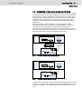
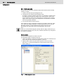
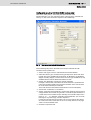
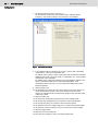


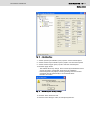
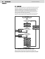

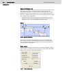
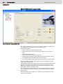
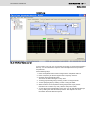

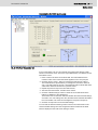
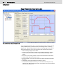

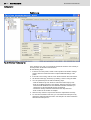
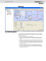


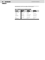


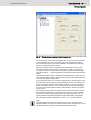
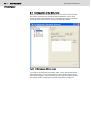
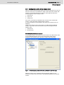
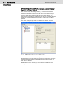

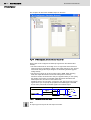
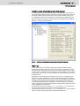
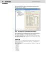
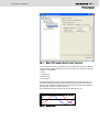

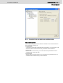
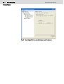
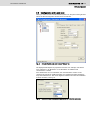
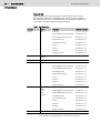
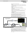


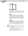

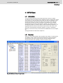
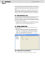

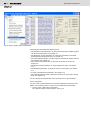
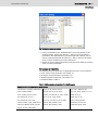
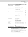
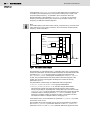
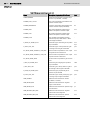

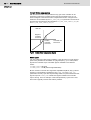
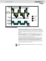
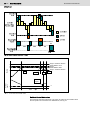

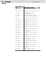


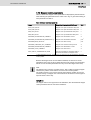


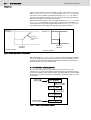
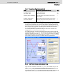
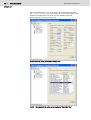
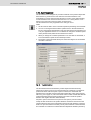

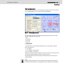


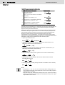
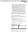


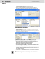

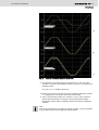


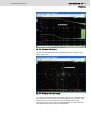


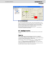
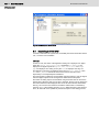
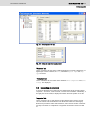

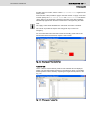

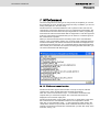

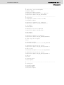
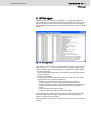

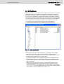
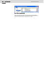
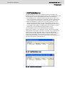


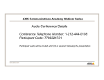


![[Download] azionamenti-hcs01](http://vs1.manualzilla.com/store/data/006141009_1-1242967de3765f3b826dc0b688197751-150x150.png)