1
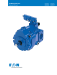
Variable-speed pressure and flow control system Sytronix DFEn 5000 RE 62241/04.13 Replaces: 12.11 1/22 Type SYDFEn-3X With axial piston variable displacement pump A10VSO.../32 Size 71 to 180 Component series 3X Maximum operating pressure 280 bar H7410_d Table of contents Contents Features Page Features 1 Ordering code 2 Section 6 Schematic diagram 7 Technical data 9 An SYDFEn-3X control system is used for the electro-hydraulic control of swivel angle, pressure and power/torque of an axial piston variable displacement pump. The control system consists of the following components: - Axial piston variable displacement pump A10VSO.../32 Electrical connection 11 - VT-DFPn-2X proportional valve as pilot valve including inductive position transducer for valve position detecting. The pilot valve contains electronics for system control. Closed-loop control quality 12 - Position transducer for detecting the swivel angle Transition function 12 Dimensions 14 - Pressure transducer with suitable signal level and dynamics (optionally HM 16, otherwise separate order) Accessories for through-drives 16 Dimensions: Through-drives 17 Torsionally flexible couplings for attachment to a standard electric motor 21 Project planning information 22 More information about this control system 22 - Preload valve with integrated pressure relief function SYDZ (optional) Information on available spare parts: www.boschrexroth.com/spc 2/22 Bosch Rexroth AG Hydraulics Type SYDFEn-3X RE 62241/04.13 Ordering code: Pump of the Sytronix DFEn 5000 control system SYDFEn-3X/ 071 R - V R B 22 U99 - 0000 1 2 3 4 5 6 7 8 9 … See following pages 1 Series Control system with internal digital electronics, variable-speed, DFEn 5000 2 Size Displacement cm³ SYDFEn-3X 071 71 100 100 140 140 180 180 3 Direction of rotation looking at the drive shaft Clockwise ● ● ● ● R 4 Hydraulic fluid Mineral oil according to DIN 51524 (HL/HLP) ● ● ● ● V 1¼" 1½" - 1¾" - 1¾" - S R ● ● ● ● B ● ● ● - 22 ● ● ● ● 32 ● ● ● ● U99 ● ● ● ● ● ● ● ● ● - 2) ● - 2) ● ● - 0000 0479 0487 0541 5 6 7 8 9 Drive shaft variant Splined shaft profile SAE J 744 1) Splined shaft profile SAE J 744 (higher through-drive torque) Connection flange according to ISO 30319-2 (4-hole) ISO 4-hole Subplate design Without shock and vibration absorption (pre-compression volume, PCV) With shock and vibration absorption (pre-compression volume, PCV; not with base pump variant 0487 or 0541) Through-drive Universal through-drive U99 closed operationally safe with end cover in the factory; for components for the adaptation of more pump stages, see the table on page 16 Base pump variant Standard (internal pilot oil) External supply External supply + regenerative operation Regenerative operation without external supply ● = Available - = Not available Preferred program 1) ANSI B92.1a-1976, 30° pressure angle, flat root, side fit, tolerance class 5 2) Size 140 with subplate 22 (without PCV) is always suitable for regenerative operation; thus, the option is omitted. - RE 62241/04.13 Type SYDFEn-3X 3/22 Hydraulics Bosch Rexroth AG Ordering code: Pilot and preload valve of the Sytronix DFEn 5000 control system SYDFEn-3X/ 071 R - V R B 22 U99 - 0000 - A 1 6 7 16 17 10 * 11 12 13 14 15 16 17 Valve, installation orientation of integrated electronics (see below) Radially to the pump axis Folded 90° in the direction of the subplate 0 2 Additional functions Teach-in version for cyclic operation Real-time version (speed calculation without teach-in) A R Electronics assembly, options Standard 0 (description of the connectors on page 11) Current input 4...20 mA Voltage input 0...10 V Voltage input 1...10 V Voltage input 0.5...5 V 1) X1 X1 X1 X2 ● Pressure transducer HM 16, measurement range 315 bar (0.5...5 V) with connection cable 0.5 m for direct connection to X2 (only in connection with actual pressure value input F) without pressure transducer Preload valve with integrated pressure limitation Pressure limitation to 200 bar (tolerance ±8 bar) 2) Pressure limitation to 250 bar (tolerance ±10 bar) 2) Pressure limitation to 300 bar (tolerance ±12 bar) 2) without preload valve Further details in the plain text e.g. SO variant High-speed version 0.5...5 V A C Parameter settings ex factory 15 9 2 - Spool design Standard 4-groove spool Actual pressure value input 14 8 L 1...10 V 13 5 F 0...10 V 12 4 0 4...20 mA 11 3 A Connector 10 2 0 ● C V E F ● L ● X ● ● ● ● ● 1 2 3 X 019 Note on feature 11: Valve, installation orientation of the integrated electronics Clockwise direction of rotation, installation orientation 0 Clockwise direction of rotation, installation orientation 2 1) With the SYDFEn control system with the additional function (feature 12 of the ordering codes) "Teach-in version for cyclic operation" and with analog interfaces, the connector X2 cannot be used as an actual pressure value input. Therefore, a separate pressure transducer has to be used and connected to connector X1 in this case. 2) The pressure relief function of the preload valve is designed for a maximum speed of 1800 1/min for size 140 and for a maximum speed of 1500 1/min for size 180. Higher speeds are available on request. 4/22 Bosch Rexroth AG Hydraulics Type SYDFEn-3X RE 62241/04.13 Example of name plate Word mark Material short text Material number, serial number underneath Date of manufacture Production order number MNR: R123456789 SN: 1 FD: 09W10 SYDFEN-3X/100R-VSB32U99-0000-A0A0VXX Designation of origin 000120984388 SN Manufacturing number 7087 Made in Germany 73939649 ROTATION Plant Indication of direction of rotation MADE .. . . . . . . . . . . . . . . . Production location Notice: For enquiries regarding the control system, material number, fabrication order number, serial number, and date of manufacture are necessary. RE 62241/04.13 Type SYDFEn-3X Hydraulics Bosch Rexroth AG Ordering code: Accessories Version 04/2013, enquire availability Accessories for Sytronix DFEn 5000 Material number Data sheet Mating connector 12-pin for central connection X1 without cable (assembly kit) R900884671 08006 Mating connector 12-pin for central connection X1 with cable set 2 x 5 m R900032356 Mating connector 12-pin for central connection X1 with cable set 2 x 20 m R900860399 Mating connector for interface X3, M12, straight, can be connected independently, 5 pins, shielded, A coded, cable diameter 6...8 mm R901076910 Pressure transducer HM 20-1X, measurement range 400 bar (4...20 mA) R901295669 30270 Pressure transducer HM 20-1X, measurement range 400 bar (0.1...10 V) R901295670 30270 Pressure transducer HM 17-1X measurement range 315 bar (4...20 mA) R900773065 30269 Pressure transducer HM 17-1X measurement range 315 bar (0.1...10 V) R900773124 30269 Test device VT-PDFE-1-1X/V0/0 R900757051 29689-B Compact power supply unit VT-NE32-1X R900080049 29929 Converter USB/serial for laptops without serial interface, VT-ZKO-USB/S-1-1X/V0/0 R901066684 Cable for connecting a Win-PED PC (RS232) to the X2 interface, length 3 m R901156928 T connector for the simultaneous connection of a WIN-PED PC (RS232) and use of the pressure transducer at connector X2 R901117164 More accessories Page Accessories for through-drives 16 Torsionally flexible couplings for attachment to a standard electric motor 21 5/22 6/22 Bosch Rexroth AG Hydraulics Type SYDFEn-3X RE 62241/04.13 Section 5 11 3 18 16 17 100 % 2 +100 % 4 1 14 15 7 6 12 8 13 9 10 1 Swash plate 12 Integrated electronics 2 Pilot valve 13 Connector X1 3 Counter piston 14 Connector X2 for connection of the HM 16 pressure transducer 4 Actuating piston 5 Spring 6 Inductive position transducer for valve position 7 Swivel angle/position sensor 8 Proportional solenoid 9 Valve spool 10 Spring 11 Pre-compression volume PCV 15 Mating connector X3 for connecting the CAN bus 16 Drive shaft 17 Connection flange 18 Through-drive U99 closed with cover RE 62241/04.13 Type SYDFEn-3X Hydraulics Bosch Rexroth AG Schematic diagram: Actuating system supplied internally Actuator (qV; p) P1 P1 20 bar T MP1 Preload valve (optional) A A T P Optional 1) U/I Pressure transducer P T P PP Bleeding Pilot valve VT-DFPn P B P U s Pump S 1) s A U M T Signal exchange with the control (see page 11) L1 L When using the pressure transducer HM 16: Installation in P (pump) or MP1 (preload valve) in connection with electronics version "actual pressure value input F". When using an external pressure transducer: Installation in the P1 line (preferably close to the actuator) and electrical connection via central connector. When using a preload valve, the pressure transducer is to be connected to P1 or MP1. 7/22 8/22 Bosch Rexroth AG Hydraulics Type SYDFEn-3X RE 62241/04.13 Schematic diagram: Actuating system supplied externally Actuator (qV; p) Optional 2) p max P T P1 3) P U/I Pressure transducer Pilot valve VT-DFPn P T Signal exchange with the control (see page 11) s U A A P B P U M Pump P 0,2 bar S S 2) 4) Z (external pilot oil pressure) s 1) 1) 20 bar The use of an anti-cavitation valve (check valve with 0.2 bar spring) is essential in order to prevent dry-running in case of an error. Pressure transducer HM 16 HM 20 / HM 17 Mounting options P P1 L1 L 3) Maximum pressure limitation must be provided by the customer! 4) Observe the upper limit for the external pilot oil pressure (see operating instructions). Recommendation: 20 bar absolute. Comment Only in connection with actual pressure value input "F" Preferably close to the actuator Important notes on external supply: – In the case of an actuating system with external supply, the pump will - in case of voltage failure - not switch to zero stroke but to the negative stop (displacement of 100 % flow from the system to the tank). – With an active fault message, it is imperative that the machine control reacts (e.g. switching off the drive motor of the pump, interrupting the external supply of the actuating system). – The command values for pressure and flow must always be greater than zero (pcommand ≥ 3 bar, αcommand ≥ 5 %) as due to drift or tolerances, there is no exact "zero" pressure or "zero" swivel angle. Under unfavorable conditions, smaller command value provisions can lead to cavitation. – The actual pressure value must not be less than 10 bar for more than 10 minutes (lubrication). RE 62241/04.13 Type SYDFEn-3X 9/22 Hydraulics Bosch Rexroth AG Technical data (for applications outside these parameters, please consult us!) mechanical and hydraulic Vg max [cm3] Size / displacement Max. speed (standard version) n0 max [min-1] Max. speed (high-speed version) Minimum speed Max. flow (displacement) with max. speed (standard version) with max. speed (high-speed version) 1800 1) 2300 2) 50 140 / 140 1800 2) 2200 2) 180/180 1800 2) - min-1 180 230 252 308 324 - [l/min] 106.7 150 210 270 P0 max [kW] 59.7 84 84 107 118 144 151 - [kW] Tmax [Nm] 50 317 70 446 98 624 125 802 1104 778 1620 1266 1620 1266 TTotal [Nm] TD [Nm] TTotal [Nm] TD [Nm 644 548 Fax max [N] 2400 4000 4800 800 Fq [N] 1900 2300 2800 2300 Drive shaft load – Max. adm. axial force X/2 X/2 2550 2) 100 / 100 128 181 qv0 max [l/min] with nE = 1500 min–1 Max. torque (Δp = 280 bar, n0 max) Max. admissible drive torque Splined shaft S total torque Max. adm. through-drive torque Splined shaft R total torque Max. adm. through-drive torque ± Fax 1800 1) nmin with nE = 1500 min–1 Max. power (Δp = 280 bar) with max. speed (standard version) with max. speed (high-speed version) Fq 71 / 71.1 – Max. admissible radial force Weight: Pump without through-drive incl. pilot valve In addition, preload valve In addition, in case of external supply Moment of inertia around drive axis Filling quantity of the housing Nominal pressure 3) m [kg] m [kg] m [kg] JTW [kgm2] V [l] pnom 49 6.3 2 0.0087 1.6 71 75 6.3 6.3 2 2 0.0185 0.0276 2.2 3.0 280 bar 80 6.3 2 0.033 2.7 Maximum admissible operating pressure pmax 350 bar 4) Minimum operating pressure: With preload valve Without preload valve In case of external supply (20 bar) pmin pmin pmin ≥ 1 bar ≥ 20 bar > 10 bar in continuous operation; in case of operation below 10 bar, observe notices on page 8 0.8 … 5.0 0.8 … 5.0 1.0...10 1.0...10 Mineral oil (HL, HLP) according to DIN 51524 –20 ... +70 °C Admissible inlet pressure p [bar] Hydraulic fluid Hydraulic fluid temperature range ϑ Maximum admissible degree of contamination of the hydraulic fluid according to ISO 4406 Class 18/16/13 (for particle size ≤ 4/6/14 μm) 1) The values are applicable at an absolute pressure of 0.8 bar in suction port S. 2) The value is applicable at an absolute pressure of 1.0 bar in suction port S. 3) In case of higher radial forces, please consult us. 4) See also data sheet 92714. 10/22 Bosch Rexroth AG Hydraulics Type SYDFEn-3X RE 62241/04.13 Technical data (for applications outside these parameters, please consult us!) electric Operating voltage UB 24 VDC + 40 % – 5 % Operating range (short-time operation) Upper limit value UB(t)max 35 V Lower limit value UB(t)min 21 V Current consumption (in static control operation) Rated current Inom 0.6 A Maximum current Imax 1.25 A Actual pressure value input X1; pin 10 and 11 Inputs U or I Analog current inputs, load RB 100 Ω Analog voltage inputs RE ≥ 100 kΩ Digital inputs nactual / UOUT1 1) Outputs Parameterizable: 0...20 mA; 4...20 mA; 0...10 V; 0…5 V; 0.5…5 V; 0.1...10 V; 1...10 V αactual / UOUT2 2) Digital outputs Logic 0 ≤8V Logic 1 ≥ 14 V UA Imax ±10 V 2 mA UA Imax ±10 V 2 mA Logic 0 Ua < 1 V Logic 1 Ua ≥ UB – 5 V; 10 mA (short circuit proof) Ambient temperature range at the pump ϑ 0…50 °C Storage temperature range (pump+electronics) ϑ 0…70 °C Electronics design Integrated in the pilot valve (OBE) Electrical connection Protection class according to EN 60529 See page 11 Pump incl. pilot valve IP 65 with mounted and locked plug-in connectors Notice: For information on the environment simulation testing for the areas of EMC (electromagnetic compatibility), climate and mechanical load, see data sheet 30030-U. 1, 2) The outputs are parameterizable, for the condition at delivery, see page 11. RE 62241/04.13 Type SYDFEn-3X Hydraulics Bosch Rexroth AG 11/22 Electrical connection X1: Central connection Mating connector according to EN 175201-804 (12 pins), for the ordering code, see section Accessories on page 5. 7 4 3 10 11 8 33 5 6 2 9 1 90 Allocation of connector or mating connector and cable set Pin Signal Signal Type of direction signal Description 1 +UB Voltage supply IN 2 0 V = L0 Reference potential for the voltage supply - 2 Supply line Earthing connection for the electronics - Green/ yellow 3 x 1.0 mm² PE Earth 24 V DC Allocation in the cable set (accessories) 3 Fault Signals failures, e.g. cable break command / acOUT tual values, controller monitoring (logic 0 = error) 4 M0 Reference potential for analog signals 5 AI2 6 UOUT2 7 AI1 8 UOUT1 Analog input AI2 Standard: Swivel angle command value Analog output Standard: Actual swivel angle value, normalized Analog input AI1 Standard: Pressure command value Analog output Standard: Speed command value Logic 24 V - 1 White Yellow IN Analog ±10 V Green OUT Analog ±10 V Violet IN Analog 0...10 V Pink OUT Analog ± 10 V Red IN Logic 24 V Brown IN Analog Black - Analog Blue Digital input DI1 9 DI1 Depending on additional function (feature 12 of the ordering code): Supply line 10 x 0.14 mm² shielded (one end of the shield must be connected to the control!) – Teach-in version: Synchronization bit DI1 – Real-time version: Activate real-time operation Actual pressure 10 value H Actual pressure value input: Signal level deActual pressure pends on feature 14 in the ordering code. 11 value L n.c. Gray X2: Serial interface RS232 and a selectable digital input S1/pressure transducer input for HM 16 (mating connector M12) Pin Signal input 1 3 4 Pin Signal RS232 OUT, +UB 2 RxD 5 TxD 3 Reference L0 Analog input 0.5...5 V for HM 16 or Digital input 0 V low, 10 V high (max. 12 V) Depending on additional function (feature 12 of the ordering code): – Teach-in version: Digital input "Variable-speed operation on, S1" – Real-time version: Input as analog input for pressure transducer HM 16 4 5 2 1 Top view mating connector 12/22 Bosch Rexroth AG Hydraulics Type SYDFEn-3X RE 62241/04.13 Electrical connection (continued) X3: CAN bus and digital input 2 (connector M12) Pin Signal input Pin Signal CAN 1 n.c. 3 CAN GND 2 IN, digital IN2 (DI2) 4 CAN-HIGH 34 Depending on additional function (feature 12 of the ordering code): 12 – Teach-in version: Start Teach-In, S2 – Real-time version: Manual speed provision active, speed is applied according to the real-time operation status and the setting of the R parameters. 5 3 2 Top view connector 5 CAN-LOW Closed-loop control quality Notices: – The specified values are only valid when using the system-related components specified in this data sheet. – At pressures < 20 bar, higher tolerances have to be anticipated due to lower actuating forces. Swivel angle control Closed-loop pressure control 1) Linearity tolerance ≤ 1.0 % ≤ 1.5 % (≤ 1.0 % 2) Temperature error ≤ 0.5 % / 10 K ≤ 0.5 % / 10 K Hysteresis ≤ 0.2 % ≤ 0.2 % Repeatability ≤ 0.2 % ≤ 0.2 % 1) Without considering the pump pulsation 2) Using the integrated calibration function Transition function with pressure command value step with spool design "A" The specified curve shapes and control times refer to a drive speed of 1500 1/min and are only reached with an optimization of the pressure controller. 140 120 100 Pressure p [bar] → Pressure p [bar] → 120 140 pCommand 80 60 pActual 40 20 pActual 100 80 pCommand 60 40 20 0 T95% Control time → 0 T95% Control time → T 95 % in ms with a connected hydraulic fluid volume (lines and actuators) Hydraulic fluid volume T95 % <5l 150 ms 5 – 10 l 200 ms 15 – 25 l 250 ms For pressures up to 40 bar, the values of the response times are greater. RE 62241/04.13 Type SYDFEn-3X Hydraulics Bosch Rexroth AG Transition function with swivel angle command value step with spool design "A" 100 Actual swivel angle value [%] → Actual swivel angle value [%] → Size 71 p = 50 bar 80 60 40 20 0 30 100 80 60 40 20 0 30 100 80 60 40 20 0 30 Size 180 p = 50 bar 60 90 Time [ms] → 80 60 40 20 0 30 60 90 Time [ms] → 120 40 20 30 60 90 Time [ms] → 120 30 60 90 Time [ms] → 120 30 60 90 Time [ms] → 120 30 60 90 Time [ms] → 120 100 80 60 40 20 100 80 60 40 20 0 120 100 60 0 Actual swivel angle value [%] → Actual swivel angle value [%] → 120 Actual swivel angle value [%] → Actual swivel angle value [%] → Size 140 p = 50 bar 60 90 Time [ms] → 80 0 120 Actual swivel angle value [%] → Actual swivel angle value [%] → Size 100 p = 50 bar 60 90 Time [ms] → 100 100 80 60 40 20 0 13/22 14/22 Bosch Rexroth AG Hydraulics Type SYDFEn-3X RE 62241/04.13 Dimensions: Integrated electronics with installation orientation 0 (dimensions in mm) The unit dimensions of the base pump (axial piston variable displacement pump A10VSO.../32) are contained in data sheet 92714. Size 71 to 180 (Valve mounting direction "0"; shaft variant "S" or "R" with universal through-drive "U99") Preload valve (optional) Space required for removing the mating connector Space required for removing the mating connectors 60 MP1 A8 III A5 A6 I A4 A1 A6 8 A6 II T A9 Connection X2 (pressure transducer HM 16) is available with SYDFE with actual pressure value input F, as well as with SYDFEC. A3 A8 I A8 II Pilot valve attachment with clockwise direction of rotation Connection X3 (CAN bus) is available with SYDFEC. Dimensions with base pump variant "0479" or "0487" 1) Size A1 A3 1) A4 A5 A6 A6 I A6 II A8 I A8 II A8 III A9 71 146 226 158 63 254 104 150 261 159 150 301 100 151 237 158 63 247 100 147 272 164 150 360 140 162 250 158 63 257 110 147 285 182 150 377 180 162 250 158 63 257 110 147 285 182 150 387 Dimension with base pump variant 0000 or 0541 RE 62241/04.13 Type SYDFEn-3X Hydraulics Bosch Rexroth AG 15/22 Dimensions: Integrated electronics with installation orientation 2 (dimensions in mm) The unit dimensions of the base pump (axial piston variable displacement pump A10VSO.../32) are contained in data sheet 92714. Size 71 to 180 (Valve mounting direction "0"; shaft variant "S" or "R" with universal through-drive "U99") Preload valve (optional) Space required for removing the mating connector MP1 A8 III A5 A6 I A4 A1 A6 8 A6 II T A9 Space required for removing the mating connectors A3 A8 I 60 A8 II Connection X3 (CAN bus) is available with SYDFEC. Connection X2 (pressure transducer HM 16) is available with SYDFE with actual pressure value input F, as well as with SYDFEC. Pilot valve attachment with clockwise direction of rotation Dimensions with base pump variant "0479" or "0487" 1) Size A1 A3 1) A4 A5 A6 A6 I A6 II A8 I A8 II A8 III A9 71 146 146 158 63 254 104 150 181 159 150 316 100 151 157 158 63 247 100 147 192 164 150 372 140 162 170 158 63 257 110 147 205 182 150 382 180 162 170 158 63 257 110 147 205 182 150 392 Dimension with base pump variant 0000 or 0541 16/22 Bosch Rexroth AG Hydraulics Type SYDFEn-3X RE 62241/04.13 Accessories for through-drives With the introduction of A10VSO, series 32, a so-called universal through-drive for combining several pump stages is used. The required components can be seen from the following table and are to be ordered separately. The following conditions apply to the attachment pumps listed in the table: – SYDFE and A10VSO with shaft S or R – PGH with shaft R, flange U2, see data sheet 10223 – PGF3 with shaft J, flange U2, see data sheet 10213 – AZPF with shaft R, front cover R, see data sheet 10089 Note also that the flange and the through-drive (see ordering code on page 2) match. Check in the current data sheet of the gear pump whether the shaft ends have the specified dimensions. Main pump Components Universal through-drive Attachment pump SYDFE..-3X/..U99 Size 71 Size 100 Size 140/180 Size and type Throughdrive Centering Flange designation Hub Mounting kit Flange kit Hub Mounting kit Flange kit Hub Mounting kit Flange kit Hub Mounting kit Flange kit Hub Mounting kit Flange kit Hub Mounting kit Flange kit Hub Mounting kit Flange kit Hub Mounting kit Flange kit Hub Mounting kit Flange kit Hub Mounting kit Flange kit Hub R902447036 R902446836 R902436200 R902446997 R902446808 R910967813 R902447002 R902446808 R910968921 R902447015 R902446816 R910962431 R902447031 R902446836 R910943545 R902447041 R902446837 R902436083 R902447046 R902446837 R910943548 R902447038 R902446850 R902436201 R902446999 R902446809 R902436101 R902447004 R902446809 R902436105 R902447017 R902446817 R902436086 R902447023 R902446820 R910943565 R902447033 R902446850 R910943560 R902447043 R902446851 R902436101 R902447048 R902446851 R902436105 R902479709 R902446852 R902436369 R902447039 R902446850 Size 18 R902436202 SYDFE..-2X/ R902447000 R902446809 Size 28 A10 VSO / R902436102 BR31 R902447005 R902446809 Size 45 R902436204 R902447018 R902446817 Size 71 R910963436 SYDFE..-3X/.. R902447024 U99 R902446820 Size 100 A10 VSO / R910943555 BR32 R902447027 Size 140/ R902446820 180 R910932172 R902447034 PGF2, PGH2, PGH3, R902446850 AZPF R910943551 R902447044 R902446851 PGF3 R902436102 R902447049 R902446851 PGH4 R902436204 R902463283 R902446852 PGH5 R910943555 U52 82.55 mm 3/4 ″ ISO 3019-1-82-2 UB3 100 mm 7/8 ″ ISO 3019-2 100B2HW UB4 100 mm 1″ ISO 3019-2 100B2HW UB8 160 mm 1¼″ ISO 3019-2 160B4HW UB9 180 mm 1½″ ISO 3019-2 180B4HW UB7 180 mm 1¾″ ISO 3019-2 180B4HW U01 82.55 mm 5/8 ″ U68 101.6 mm 7/8 ″ ISO 3019-1-82-2 ISO 3019-1-101-2 U04 101.6 mm 1″ ISO 3019-1-101-2 U24 127 mm 1½″ ISO 3019-1-127-2 Combinations are only possible with shaft ends according to SAE J744 1) 1) ANSI B92.1a-1976, 30° pressure angle, flat root, side fit, tolerance class 5. A mounting kit comprises the flange kit and hub; a flange kit comprises the flange, seals and mounting materials. RE 62241/04.13 Type SYDFEn-3X Hydraulics Bosch Rexroth AG 17/22 Dimensions: Through-drives (dimensions in mm) Before determining your construction, please request a binding installation drawing. U52 Flange ISO 3019-1-82-2 Hub for splined shaft according to ANSI B92.1a-1996 M10x25 (8x ) A Size 100...180 A-B M12x25 (4x) 22 15 3/4 ″ 11T 16/32DP 1) 13 Size 71 06. 5 Size A1 A2 A3 71 299 38 17.5 100 360 38 17.5 140 377 38 17.5 180 387 38 17.5 Ø82.55 +0.05 +0.02 Ø1 (SAE J744 - 19-4 (A-B)) M10; 16 deep A3 A2 up to pump mounting face A1 B UB3 Flange ISO 3019-2 - 100B2HW Hub for splined shaft according to ANSI B92.1a-1996 A M10x25 (8 x) Size 100...180 M10x25 (4x) A-B 22 15 7/8 ″ 11T 16/32DP 1) 9 Size 71 Ø1 UB4 M12; 18 deep A2 up to pump mounting face A1 M10x25 (8 x) A-B 22 15 9 Ø 100 +0.05 +0.02 40 1) A2 A3 71 299 41 16.5 100 360 41 16.5 140 377 41 16.5 180 387 41 16.5 1 ″ 15T 16/32DP 1) Ø1 B A1 A3 Flange ISO 3019-2 - 100B2HW Hub for splined shaft according to ANSI B92.1a-1996 A Size Ø 100 +0.05 +0.02 45° 40 B (SAE J744 - 22-4 (B)) M12; 18 deep A2 up to pump mounting face A1 30° pressure angle, flat root, side fit, tolerance class 5 A3 (SAE J744 - 25-4 (B-B)) Size A1 A2 A3 71 299 45.9 16.9 100 360 45.9 16.9 140 377 45.9 16.9 180 387 45.9 16.9 18/22 Bosch Rexroth AG Hydraulics Type SYDFEn-3X RE 62241/04.13 Dimensions: Through-drives (dimensions in mm) Before determining your construction, please request a binding installation drawing. UB8 Flange ISO 3019-2 - 160B4HW Hub for splined shaft according to ANSI B92.1a-1996 141 .4 A M10x25 (8 x) Size 100...180 M16; 20 deep A-B 22 15 1 ¼ ″ 14T 12/24DP 1) 9 Size A1 A2 A3 71 299 55.4 17.9 100 360 55.4 17.9 140 377 55.4 17.9 180 387 55.4 17.9 141 .4 Ø 160 +0.05 +0.02 (4 x) (SAE J744 - 32-4 (C)) M12x25 (4x) Size 71 B A3 Flange ISO 3019-2 - 180B4HW Hub for splined shaft according to ANSI B92.1a-1996 158.4 A M16; 20 deep (4 x) M10x25 (8x) A -B Size 100...180 22 15 1 ½ ″ 17T 12/24DP 1) 9 (SAE J744 - 38-4 (C-C)) Size A1 A2 A3 100 360 61.9 20.4 140 377 61.9 20.4 180 387 61.9 20.4 158.4 Ø 180 +0.05 +0.02 UB9 A2 up to pump mounting face A1 M12x25 (4x) A3 Size 71 B A2 up to pump mounting face A1 UB7 Flange ISO 3019-2 - 180B4HW Hub for splined shaft according to ANSI B92.1a-1996 158.4 A M16; 20 deep (4 x) M10x25 (8x) A-B 22 15 9 158.4 Ø 180 +0.05 +0 02 Size 100...180 1 ¾ ″ 13T 8/16DP 1) M12x25 (4x) B Size 71 A2 up to pump mounting face A1 1) 30° pressure angle, flat root, side fit, tolerance class 5 A3 (SAE J744 - 44-4 (D)) Size A1 A2 A3 140 377 75 Request 180 387 75 Request RE 62241/04.13 Type SYDFEn-3X Hydraulics Bosch Rexroth AG 19/22 Dimensions: Through-drives (dimensions in mm) Before determining your construction, please request a binding installation drawing. U01 Flange ISO 3019-1-82-2 Hub for splined shaft according to ANSI B92.1a-1996 A M10x25 (8 x) Size 100...180 A -B M12x25 (4x) 5/8 ″ 9T 16/32DP 1) 22 15 13 Size 71 Ø1 06. Size A1 A2 A3 71 299 31.8 19.3 100 360 31.8 Request 140 377 31.8 Request 180 387 31.8 Request Ø82.55 +0.05 +0.02 45° 5 (SAE J744 - 16-4 (A)) M10; 16 deep B U68 A3 A2 up to pump mounting face A1 Flange ISO 3019-1-101-2 Hub for splined shaft according to ANSI B92.1a-1996 A M10x25 (8 x) Size 100...180 M12x25 (4x) A-B 7/8 ″ 13T 16/32DP 1) 22 15 13 Size 71 Ø1 46 +0.05 Ø 101 .6 +0.02 (SAE J744 - 22-4 (B)) Size A1 A2 A3 71 299 41 16.5 100 360 41 16.5 140 377 41 16.5 180 387 41 16.5 M12; 22 deep B U04 A3 A2 up to pump mounting face A1 Flange ISO 3019-1-101-2 Hub for splined shaft according to ANSI B92.1a-1996 A M10x25 (8 x) Size 100...180 M12x25 (4x) A-B 22 15 1 ″ 15T 16/32DP 1) 13 Size 71 Ø1 Ø 101 .6 +0.05 +0.02 46 M12; 22 deep B 1) A3 A2 up to pump mounting face A1 30° pressure angle, flat root, side fit, tolerance class 5 (SAE J744 - 25-4 (B-B)) Size A1 A2 A3 71 299 45.9 16.9 100 360 45.9 16.9 140 377 45.9 16.9 180 387 45.9 16.9 20/22 Bosch Rexroth AG Hydraulics Type SYDFEn-3X RE 62241/04.13 Dimensions: Through-drives (dimensions in mm) Before determining your construction, please request a binding installation drawing. U24 Flange ISO 3019-1-127-2 Hub for splined shaft according to ANSI B92.1a-1976 M10x25 (8x) Size 100...180 1 ½ ″ 17T 12/24DP 1) 22 A-B Ø127 +0.05 +0.02 136 +0.2 45° Ø180 M16 (4x), 22 Deep 15 A2 up to pump mounting face A1 1) 30° pressure angle, flat root, side fit, tolerance class 5 A3 Size 140/180 9 A3 Size 100 (SAE J744 - 38-4 (C-C)) Size A1 A2 A3 100 360 61.9 20.4 140 377 70.5 10.5 180 387 70.5 10.5 RE 62241/04.13 Type SYDFEn-3X Hydraulics Bosch Rexroth AG 21/22 Torsionally flexible couplings for attachment to a standard electric motor Motor SYDFEn-3X Size 71 Size 100 Size 140/180 Shaft S or R, 1¼ ″ Shaft S, 1½ ″ Shaft S, 1¾ ″ Frame size/ characteristic value Shaft diameter 160/0 42 R900228413 180/0 48 R900240468 R900242567 200/0 55 R901038021 R901104689 R901038048 225/0 60 R900228375 R901050508 R900988121 250/0 65 R900986404 R901046864 R900708084 280/0 75 R900218487 315/0 80 315/1 80 1) Up to 40 °C R901055216 R901052451 R901046894 1) R901041730 1) R901046885 22/22 Bosch Rexroth AG Hydraulics Type SYDFEn-3X RE 62241/04.13 Project planning information – Always shield command and actual value lines. Observe the notices in the instructions 30014-B, section 7.6. – The distance to aerial lines or radios must be at least 1 m. – Do not lay signal lines close to power cables. – For supplementary notices on the SYDFEn control system, see the operating instructions (see section "More information about this control system" on this page). More information about this control system Operating instructions for SY(H)DFEn 30014-B User manual CANopen interface for SY(H)DFEn 30014-02-Z Universal through-drive U99 for connecting two pumps into one combination 95581 Data sheet for axial piston variable displacement pump A10VSO../32 92714 Data sheet for pilot valve VT-DFP.-2X 29016 Data sheet for pump preload valve SYDZ 0001-1X 29255 Data sheet for swivel angle sensor VT-SWA-1-1X 30268 Data sheet for pressure transducer HM 20-1X 30270 Data sheet for pressure transducer HM 16-1X 30266 Data sheet for pressure transducer HM 17-1X 30269 Operating instructions for test device VT-PDFE 29689-B Current information is also available on the Internet at http://www.boschrexroth.com/sydfe (English) or http://www.boschrexroth.de/sydfe (German). Bosch Rexroth AG Hydraulics Zum Eisengießer 1 97816 Lohr am Main, Germany Phone +49 (0) 93 52 / 18-0 [email protected] www.boschrexroth.de © This document, as well as the data, specifications and other information set forth in it, are the exclusive property of Bosch Rexroth AG. It may not be reproduced or given to third parties without its consent. The data specified above only serve to describe the product. No statements concerning a certain condition or suitability for a certain application can be derived from our information. The information given does not release the user from the obligation of own judgment and verification. It must be remembered that our products are subject to a natural process of wear and aging. RE 62241/04.13 Type SYDFEn-3X Hydraulics Bosch Rexroth AG 23/22 Notes Bosch Rexroth AG Hydraulics Zum Eisengießer 1 97816 Lohr am Main, Germany Phone +49 (0) 93 52 / 18-0 [email protected] www.boschrexroth.de © This document, as well as the data, specifications and other information set forth in it, are the exclusive property of Bosch Rexroth AG. It may not be reproduced or given to third parties without its consent. The data specified above only serve to describe the product. No statements concerning a certain condition or suitability for a certain application can be derived from our information. The information given does not release the user from the obligation of own judgment and verification. It must be remembered that our products are subject to a natural process of wear and aging. 24/22 Bosch Rexroth AG Hydraulics Type SYDFEn-3X RE 62241/04.13 Notes Bosch Rexroth AG Hydraulics Zum Eisengießer 1 97816 Lohr am Main, Germany Phone +49 (0) 93 52 / 18-0 [email protected] www.boschrexroth.de © This document, as well as the data, specifications and other information set forth in it, are the exclusive property of Bosch Rexroth AG. It may not be reproduced or given to third parties without its consent. The data specified above only serve to describe the product. No statements concerning a certain condition or suitability for a certain application can be derived from our information. The information given does not release the user from the obligation of own judgment and verification. It must be remembered that our products are subject to a natural process of wear and aging.