1
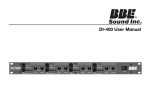
DIGIMAX Eight Channel Microphone Preamplifier with Dual Domain Limiters and Digital Outputs User’s Manual PreSonus Corporation DigiMax E I G H T C H A N N E L M I C R O P H O N E P R E A M P L I F I E R With Dual Domain Limiters and Digital Outputs USERS MANUAL Version 1.0 2000, PreSonus Audio Electronics, Incorporated. All rights reserved. W A R R A N T Y PreSonus Limited Warranty PreSonus Audio Electronics Inc. warrants this product to be free of defects in material and workmanship for a period of one year from the date of original retail purchase. This warranty is enforceable only by the original retail purchaser. To be protected by this warranty, the purchaser must complete and return the enclosed warranty card within 14 days of purchase. During the warranty period PreSonus shall, at its sole and absolute option, either repair or replace, free of charge, any product that proves to be defective on inspection by PreSonus or its authorized service representative. To obtain warranty service, the purchaser must first call or write PreSonus at the address and telephone number printed below to obtain a Return Authorization Number and instructions of where to return the unit for service. All inquiries must be accompanied by a description of the problem. All authorized returns must be sent to the PreSonus repair facility postage prepaid, insured and properly packaged. PreSonus reserves the right to update any unit returned for repair. PreSonus reserves the right to change or improve the design of the product at any time without prior notice. This warranty does not cover claims for damage due to abuse, neglect, alteration or attempted repair by unauthorized personnel, and is limited to failures arising during normal use that are due to defects in material or workmanship in the product. Any implied warranties, including implied warranties of merchantability and fitness for a particular purpose, are limited in duration to the length of this limited warranty. Some states do not allow limitations on how long an implied warranty lasts, so the above limitation may not apply to you. In no event will PreSonus be liable for incidental, consequential or other damages resulting from the breach of any express or implied warranty, including, among other things, damage to property, damage based on inconvenience or on loss of use of the product, and, to the extent permitted by law, damages for personal injury. Some states do not allow the exclusion of limitation of incidental or consequential damages, so the above limitation or exclusion may not apply to you. This warranty gives you specific legal rights, and you may also have other rights, which vary form state to state. This warranty only applies to products sold and used in the United States of America. For warranty information in all other countries please refer to your local distributor. PreSonus Audio Electronics, Inc. 7257 Florida Blvd. Baton Rouge, LA 70806 (225) 216-7887 2000, PreSonus Audio Electronics, Incorporated. All rights reserved. TABLE OF CONTENTS 1 Overview Introduction 5 Features 6 2 Controls & Connections Front Panel Basic Layout 9 Back Panel Basic Layout 12 Power Supply 3 14 Operation Dynamic Microphones 15 Phantom Powered Microphones 15 Instrument Input 15 Enhancement 15 4 Technical Specifications 17 3 This page intentionally left blank. 4 1 OVERVIEW 1 . 1 I N T R O D U C T I O N Thank you for purchasing the PreSonus DigiMax Eight Channel Microphone / Instrument Preamplifier with Dual Domain Limiters and Digital Outputs. This digital pre-amp has been designed and constructed using the very latest in components and technology to provide its user crystalline audio reproduction for an infinite period of time. We at PreSonus believe the DigiMax to be an exceptional sounding unit and an exceptional value. Contact us at 1-800-750-0323 with your questions or comments you may have concerning this unit or its operation. PreSonus Audio Electronics is committed to the philosophy of constant product improvement. Our experience has taught us the best way to convert this philosophy into action is by listening to the experts on our gear, our valued customers. We appreciate the support you have shown us through the purchase of this product. Please pay close attention when connecting your DigiMax to your system. Improper grounding is one of the most common causes of noise problems encountered in the recording or sound reinforcement environments. We recommend scanning this manual before hooking up your DigiMax to your system so you may familiarize yourself with its functions and features. Good luck and enjoy your DigiMax! 1 . 2 F E A T U R E S The following is a summary of the features of the PreSonus DigiMax Dual Servo Mic Pre. Each channel of your DigiMax contains a Class A discrete input buffer followed by a dual servo gain stage. This provides ultra low noise and wide gain control allowing the DigiMax user to boost desirable signal without increasing unwanted background noise (NO capacitors!) 5 OVERVIEW 48V Phantom Power. Each channel of the DigiMax has 48V Phantom power available. When the Phantom power switch is engaged, power is supplied at a constant rate. This assures optimum performance of your condenser microphone(s) and that it will be free of distortion associated with insufficient power. This switch is located on the back panel adjacent to the XLR input. Phase Reverse Switch. A phase reverse switch is provided on channels One and Two. This switch enables the user to invert the phase of a microphone when phase cancellation is noted. The phase reverse switch allows the operator to avoid phase cancellation when identical microphones are used in close proximity to one another. The phase reverse switch also can compensate for different XLR connector hook-ups where pin connections have been inverted. -20 dB Pad. A -20 dB pad is available on each channel of the DigiMax for reducing in-coming signal levels to the unit. Using this pad can provide a more manageable signal from high output devices giving the operator greater control over the incoming signal and a much reduced chance of over-driving the input and thereby avoiding distortion. Enhance. The Digimax provides an EQ Enhancement feature on each channel. Engaging this switch gives the processed signal a cut of 3 dB between 250 Hz and 5kHz. This has a smoothing effect on mid-range heavy signals and gives a flatter response characteristic. Sample Rate Selector. The Digimax has a switch on the front panel that lets the operator choose the sample rate. It provides selectable rates of 32k, 44.1k and 48k. EXT CLOCK. When the External clock switch is engaged the Digimax goes into “chase” mode and automatically recognizes 6 OVERVIEW which of the three sampling rates is required for optimum synchronization. Dual Concentric Control. Each channel of the DigiMax has a dual concentric rotary control for adjusting the channel’s gain (inner) and for selecting the dual domain limiter’s threshold (outer). Analog Output. The rear panel of the DigiMax contains analog impedance balanced outputs for each channel. These outputs provide an analog duplicate of the digital output of the unit. This duplication of the digital output allows the user to monitor the analog output with a mixing console and overcoming the “latency” problem (time delay) that may be encountered when trying to record in “digital”. Digital Optical Output. The DigiMax has a adat lightpipe output that can be used with any commercially available digital optical cable. This cable can supply eight simultaneous outputs. Digital Output. The DigiMax has a chassis mounted 9 pin connector which can provide either AES/EBU or SP/DIF outputs depending on which model of cable is used as well as the internal configuration of the jumpers on the output card of the unit. 7 2 CONTROLS & CONNECTIONS 2 . 1 F R O N T P A N E L B A S I C L A Y O U T Notice that the front panel is divided into Eight Preamplifier sections, Sample Rate Selector with Indicators and External Clock Switch. Channel One and Channel Two each have a Hi-Z input (Channel Three through Channel Eight do not have a Hi-Z input). Both Channels One and Two contain: • Phase Reverse Switch • -20dB Pad • Enhancement Switch • Hi-Z Input • Dual Concentric Control (Inner-Gain / Outer-Limiter Threshold) • -20/Clip/Limit LED’s Channels Three through Eight contain: • PAD 8 • ENH • Dual Concentric Control (Inner-Gain/Outer-Limiter Threshold) • -20/Clip/Limit LED’s Dual Concentric Control: Gain. The inner concentric control provides 60dB of gain to the processed signal. The amplifier has inherent gain of 12dB thus delivering a total gain possibility of 72dB. LIMITER THRESH. The outer concentric control sets the Threshold of the dual domain limiter. The threshold ranges from 0 to +24dB. -20 / Clip / Limit LED’s The three LED’s found on each channel are provided to serve different functions: -20. The LED farthest to the left is labeled –20 and serves to monitor whether or not signal is present at the channel output. Clip. The LED labeled Clip activates at a pre limiter signal level of +24 dB. Care should be taken to avoid using signal levels that cause this LED to become active. Signal levels that reach or exceed this amount of output will cause undesirable artifacts (distortion) in the channel output signal that is being indicated by this LED. The signal level is reduced by rotating the channel’s inner concentric control, counter-clockwise. LIMIT. The LED farthest to the right is labeled LIMIT. This LED is activated by signal levels that reach or exceed the level that is predetermined by the Threshold setting selected (outer concentric control). The setting of this control selects the point at which the 9 limiter acts upon the signal coming through the channel. Proprietary technology of the dual domain limiter allows it to act instantaneously upon the signal at Threshold. The unique benefits of peak limit control have been combined with the desirable audible results of RMS limiting to provide DigiMax users with completely transparent overload protection for digital recording. (NOTE: It is possible to get some very cool effects by driving the limiter with transients. These effects may be achieved by using low threshold settings and high gain. Care must be taken to avoid distortion.) § Sample Rate Selector § LED Indicators -(32k 44.1k-48k) § EXT Clock The section at the extreme right of the front panel contains the Sample Rate Selector Switch with LED indicators provided for 32k, 44.1k and 48k. This section also contains a switch labeled EXT. CLOCK. When this switch is engaged the operating clock rate of 32k, 44.1, or 48k will be determined by the incoming signal from an external device through the Word Clock In input on the back panel of the DigiMax. 2 . 2 B A C K P A N E L B A S I C L A Y O U T Digital Optical Output. An adat optical output (lightpipe) is provided on the rear panel of the DigiMax. Eight simultaneous 24bit outputs are possible when using the optical out. Digital Output Connector. A female nine pin (DB9) connector on the rear panel of the DigiMax provides 24bit digital output. This connector comes configured from PreSonus for AES/EBU output (4 pair stereo) when used with the (optional) Model No. 510- DMAX 007 cable available at an 10 authorized PreSonus dealer or which can be ordered directly from PreSonus. S/PDIF outputs can also be obtained from an Authorized PreSonus dealer by purchasing a Model No.510-DMAX008 cable or by ordering the cable from PreSonus. The use of the S/PDIF output requires re-configuring the jumpers on the output card of the DigiMax. While this is a simple operation, care must be taken when moving the jumpers. A diagram and complete instructions regarding this procedure are included with the 510-DMAX008 cable. Should you need further assistance, contact Customer Support at PreSonus by calling 800-750-0323 between the hours of 10:00 AM and 5:00 PM CST Word Clock Out/In. The Word clock output and input are accessed through separate BNC connectors. The internal sample rate can be set to send 32k, 44.1k, or48k. The Word Clock In scans the incoming information and automatically synchs to the necessary sample rate. +48V. A switch labeled +48V is located next to each microphone input. This switch may be engaged to provide phantom power for condensor mics and any other device, which may require phantom power by way of the XLR input. This power is supplied at a constant rate to allow use of all eight inputs, simultaneously, without any degradation of audio quality. PIN 1 GND PIN 2 +48v PIN 3 +48v XLR connector wiring for Phantom Power ANALOG OUTPUT. Each channel of the DigiMax has an analog output that parallels the digital signal being sent from the associated channel. This output can be very useful for monitoring purposes by helping in overcoming the time discrepancy that may be encountered in some digital recording situations. This output is impedance balanced and the connection is wired as follows: TIP Signal 11 51ohms RING 51ohms SLEEVE GND Analog Impedance Balanced wiring diagram 2 . 3 E X T E R N A L P O W E R S U P P L Y The External Power Supply supplied with the DigiMax has two cords attached to the unit. The cable labeled DC/OUT goes to the DC input on the DigiMax pre-amp. The cord labeled AC goes to the electrical power source . The DigiMax is configured at the factory to operate on specific voltages. Make sure the unit is setup for the correct voltage available in the locale where the unit is to be operated. If you are unsure whether or not the unit you have is configured for the available voltage in you area, contact an Authorized PreSonus dealer in your area before use to avoid physical injury to the user or severe damage to the unit could result. The four green LED’s on the face indicate the presence of current on the power rails. V1=+5 volts, V2=16.5 volts, V3=-16.5 volts, and V4=+48 volts respectively. WARNING! Before powering up your DigiMax for the first time make certain that the stated power requirement of the unit (as stated on top of the external power supply) matches the voltage supplied in the country where the unit will be operated (USA = 115V). Failure to do so could result in injury or even death to the user and the probability of irreparable damage to the unit is highly likely. 12 3 OPERATION 3 . 1 D Y N A M I C M I C R O P H O N E S Dynamic microphones are characterized by lower output levels. Hence, more gain is needed to amplify a dynamic microphone to operating level. Occasionally it is necessary to add the –20dB pad to the microphone to avoid distortion (e.g. when recording percussion). Do not use phantom power when using dynamic microphones. 3 . 2 P H A N T O M P O W E R E D M I C R O P H O N E S Phantom powered microphones such as condensors and some ribbon microphones require external power to pre-amplify the microphone acoustic pickup. These microphones typically have much higher output than dynamic microphones. Hence the –20dB pad is almost always necessary when close micing to avoid clipping the amplifier. 3 . 3 I N S T R U M E N T I N P U T The instrument inputs on channels one and two are designed to handle ¼” plugs from instruments such as electric guitars and basses. These instrument inputs are ultra high impedance amplifiers designed to allow the audio potential of an acoustic or electric instrument pickup to be fully realized. Care should be taken not to overdrive these inputs with the signals from instruments with on-board preamplifiers. 3 . 4 E N H A N C E M E N T The Enhancement function of the DigiMax gives the processed signal a 3dB cut from 250 Hz to 5kHz. The slope of this frequency cut has a smoothing effect on the signal that is being processed. For certain voices and microphones, which may tend to possess a characteristic mid-range rise, this feature will have the effect of flattening the mids. This will result in a fuller frequency response and an apparently richer; fuller sound. Experimenting with the Enhancement feature will allow you to expand the sound potential of your available microphones and instruments. The following graph is a representation of the EQ curve derived with the ENH switch, engaged. 13 4 . 1 T E C H N I C A L S P E C I F I C A T I O N S DigiMax Technical Specifications: Number of Channels Eight Input Input Impedance, XLR Input Input Impedance, Instrument Input Connectors 1.3kΩ 1MegΩ Neutrik XLR 1/4”TS Ch.1&2 only) 14 Panel Controls Gain Limiter Phase Reverse (1 & 2 only) Pad Phantom Power 0dB to +40dB 0dB to Off -20 dB +48 V (Back Panel) Meters Signal Present LED Clip LED Limit LED -20dBu +22dBu Limiter Active Output ¼ ” TRS Impedance Balanced adat lightpipe digital optical AES/EBU (4 pair stereo) S/PDIF (4 pair stereo) 51Ω 24bit 24bit 24bit Digital Sampling Rates Dither Type 32kHz, 44.1kHz, 48kHz Psycho-acoustic Performance THD + Noise (Un-weighted) Noise Floor Signal to Noise Analog Dynamic Range Power Supply Rejection Amplifier Type <0.009% -94dBu >98dB >120dB >98dB Dual Servo Power Supply Type Input Power Linear, External 100/120/220/240VAC (Factory Configured) 80 Watts 15 Physical Size Dimensions Weight Chassis Panel 1U Rack 19” X 1.75” X 7” 15 lbs. Steel Aluminum As a commitment to constant improvement, PreSonus, Inc. reserves the right to change any specification stated herein at any time in the future without notification. 16