1
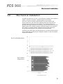
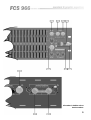
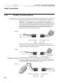
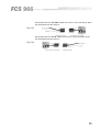
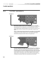
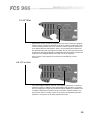
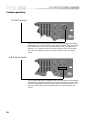
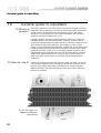
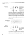
FCS 966
User Manual
1
V 1.0
BV/JMK
30 April 1998
An example of this equipment has been tested and found to comply with the following European and
international Standards for Electromagnetic Compatibility and Electrical Safety:
Radiated Emissions (EU):
EN55013
RF Immunity (EU):
EN50082/1
Mains Disturbance (EU):
EN61000/3/2
Electrical Safety (EU):
EN60065
Radiated Emissions (USA): FCC part 15 Class B
(1990) Associated Equipment
(1992) RF Immunity, Fast Transients ESD
(1995)
(1993)
IMPORTANT SAFETY INFORMATION
DO NOT REMOVE COVERS. NO USER SERVICEABLE PARTS INSIDE, REFER SERVICING TO QUALIFIED
SERVICE PERSONNEL. THIS EQUIPMENT MUST BE EARTHED.
IT SHOULD NOT BE NECESSARY TO REMOVE ANY PROTECTIVE EARTH OR SIGNAL CABLE SHIELD
CONNECTIONS TO PREVENT GROUND LOOPS. ANY SUCH DISCONNECTIONS ARE OUTSIDE THE
RECOMMENDED PRACTISE OF BSS AUDIO AND WILL RENDER ANY EMC OR SAFETY CERTIFICATION
VOID.
For continued compliance with international EMC legislation ensure that all input and output cables are wired
with the cable screen connected to Pin 1 of the XLR connectors and/or the jack plug sleeve. The input XLR Pin
1, input jack socket sleeve and Combi-Con screen connectors are connected to the chassis via a low value
capacitor, providing high immunity from ground loops whilst ensuring good EMC performance.
Please read
We have written this manual with the aim of helping installers, sound engineers and musicians alike to get the
most out of the FCS 966. We recommend that you read this manual, particularly the section on installation,
before attempting to operate the unit.
We recommend that you read this manual, particularly the section on installation, before attempting to operate
the unit as there are a number of features that may not be apparent by casual use. The manual is split into two
main sections. The first contains quick reference information, regarding the functions and operation of the unit,
while the second covers a more general background to the uses and application of the FCS 966.
We welcome any comments or questions regarding the FCS 966 or other BSS products, and you may contact us
at the address or World Wide Web site given in the warranty section.
2
Contents
Contents
1.0
Mechanical installation
5
2.0
Unpacking
6
3.0
Mains Power Connection
Mains Power
6
6
4.0
Introduction
7
5.0
5.1
5.2
5.3
5.4
5.5
Audio Connections
XLR Inputs
XLR Outputs
Jack Inputs
Jack Outputs
Combi-Con connectors
10
10
10
11
12
12
6.1
6.2
6.3
6.4
6.5
6.6
6.7
6.8
Control operations
Eq In
Gain
HP Filter
LF Contour
HF Contour
Output meter
Clip indicators
Frequency band sliders
14
14
14
15
15
16
16
17
17
7.1
7.2
7.3
General guide to equalisers
What is a graphic?
How do I use it?
What does constant Q mean?
18
18
18
19
3.1
6.0
7.0
3
Contents
8.0
8.1
8.2
8.3
8.4
8.5
8.6
9.0
10.0
4
Application examples
General Equalisation problem solving
Feedback reduction
Room equalisation
Uses for the HP Filter
Uses for the LF contour
Use for the HF contour
21
Warranty Information
25
Specifications
26
Index
27
User Notes
28
Spare Parts Information
31
21
22
22
23
24
24
Mechanical Installation
1.0
Mechanical installation
A vertical rack space of 3U (5 1/4" - 133.5mm high) is required, with a depth of
190mm, excluding connectors. Ventilation gaps are unnecessary.
If the unit is likely to undergo extreme vibration through extensive road
trucking and touring, the unit must be supported at the rear and/or sides to
lessen the stress on the front mounting flange. The necessary support can
generally be bought ready-built, as a rack tray, or the FCS 966 can be mounted
between other units. Damage caused by insufficient support is not covered by
the warranty. To prevent cosmetic damage to the front panel paint finish,
always use protective plastic cups under the rack mounting bolts.
As with any low-level signal processing electronics, it is best to avoid mounting
the FCS 966 next to a strong source of magnetic radiation or heat, for example,
a high power amplifier.
Fig 1.1 Unit dimensions.
Fig 1.2 Rack
dimensions.
5
Unpacking
Mains Power Connection
2.0
Unpacking
As part of the BSS system of quality control, we check every product carefully
before packing to ensure that it reaches you in flawless condition.
Before you go any further, please check the unit for any physical damage and
retain the shipping carton and all relevant packing materials for use, should the
unit need returning.
In the event that damage has occurred, please notify your dealer immediately,
so that a written claim to cover the damages can be initiated. Check out
section 9.0; warranty information, for more info on the warranty, and also to
record your dealer details.
3.0
Mains Power Connection
3.1 Mains Power WARNING! THIS APPLIANCE MUST BE EARTHED.
The FCS 966 must always be connected to a 3-wire earthed AC outlet. The
rack framework must also be connected to the same grounding circuit. The
unit must NOT be operated unless the power cables' EARTH (ground) wire is
properly terminated - this is important for personal safety as well as for proper
control over the system grounding.
The wires in the mains lead are colour coded in accordance with the following
code.
Green and Yellow......Earth
Blue......Neutral
Brown......Live
Those units supplied to the North American market will have an integral
moulded 3 pin connector which is provided to satisfy required local standards.
IMPORTANT: The FCS 966 is designed to use 50/60Hz AC power in one of
two voltage ranges, selectable with the mains voltage selector switch on the
rear of the unit. It is vital that the position of this switch is checked BEFORE
initial power up to ensure that it matches the local mains supply. Acceptable
input AC supply voltages range from:
115V switch position
230V switch position
90V to 132V
190V to 265V
The application of voltages outside these ranges may cause permanent damage
or erratic operation of the unit, and will invalidate the warranty.
The mains fuse carrier on the rear of the unit must be fitted with the correct
type and rating of fuse, depending on the position of the mains voltage selector
switch:
115V switch position
230V switch position
T315mA fuse
T200mA fuse
In the unlikely event of the mains fuse failing without good reason,
DISCONNECT THE UNIT FROM THE MAINS SUPPLY, and always replace
6
Introduction
with the appropriately rated fuse (as specified previously) for continued
protection against damage and fire.
Note: For USA and Canadian users, the replacement fuse must be of an
identical UL rated type fuse for continued compliance with safety standards.
4.0
Introduction
The FCS 966 is a two channel graphic equaliser that provides a generous
+/
-15dB of control range on each of 30 constant Q frequency bands. For
optimum performance, each filter band is arranged to be out of circuit if it's
sliders are left in the centre of its travel, and thus does not contribute
unnecessary noise or distortion.
In addition, a sweepable high pass filter, variable gain, and HF/LF contour
controls are provided for extra flexibility. Indication of level is provided by an
8 segment meter that reads input level when the unit is bypassed, and output
level when active. This allows accurate level matching of the equalised to
unequalised signal. Indication of overload is provided by a separate clip
indicator that simultaneously monitors the level at three critical internal points
to ensure that any overload does not go unnoticed.
When bypassed, the FCS 966 connects the output directly to the input with a
high quality relay, ensuring that a signal passes even with a loss of AC power.
The relay drive also incorporates a power on delay and AC power loss
detector, ensuring that there is no possibility of on/off thumps being generated
by the unit.
For installation flexibility, XLR, Jacks and pluggable terminal block (combi-con)
connectors are provided as standard, with transformer isolation on both the
inputs and outputs available as an option. The mains lead is a standard
detachable IEC type.
7
The FCS 966
Fig 4.1 Front Panel
Fig 4.2 Rear Panel
8
All numbers in bubbles refer to
Section numbers.
9
Audio Connections
5.0
Audio Connections
5.1 XLR Inputs
There are 2 input sockets on the rear panel of the FCS 966; Input 1 and 2. Each
is electronically balanced on standard 3 pin female XLRs at an impedance
greater than 10k Ohms. The ‘HOT, +, or in phase’ connection is to pin 2 and
the ‘COLD, -, or out of phase’ connection is to pin 3. Pin 1 is internally
connected to the chassis earth via a low value capacitor. This ensures freedom
from ground loops whilst allowing good EMC performance. The screen of the
input cable should be connected to pin 1 to ensure that EMC regulations are
being met, and the cable shield ground should also be connected to the
equipment which is providing the input signal.
Fig 5.1
966
When feeding the FCS 966 from unbalanced sources, connect the signal
conductor to pin 2 and the cable screen to pins 1 and 3. Transformer isolated
inputs are available as a dealer fitted option.
Fig 5.2
966
5.2 XLR Outputs
The output signals are electronically balanced and fully floating. Full
headroom is available into any load of 600 Ohms or greater. The signal ‘HOT,
+, or in phase’ signal is to pin 2, the ‘COLD, -, or out of phase’ signal is to pin
3, with pin 1 being connected directly to the chassis.
Fig 5.3
966
10
When using the FCS 966 to drive unbalanced inputs, best performance is
usually obtained by connecting the FCS 966s ‘+’ signal to the equipment signal
pin and the ‘-’ signal to the equipment shield.
Fig 5.4
966
The FCS 966 shield should normally be connected to the equipment shield,
preferably at the equipment end. Transformer isolated outputs are also
available as a dealer fitted option.
5.3 Jack Inputs
The jack inputs are electrically identical to the XLR inputs. The ‘HOT, +, or in
phase’ connection is to the jack plug tip, the ‘COLD, - or out of phase’
connection to the ring. The shield is internally connected to the chassis earth
via a low value capacitor. This ensures freedom from ground loops whilst
allowing good EMC performance. The screen of the cable must be connected
to the jack plug shield to ensure continued compliance with EMC regulations.
The cable shield ground should be connected to the equipment which is
providing the input signal.
Fig 5.5
966 Jack Input
When feeding the FCS 966 from unbalanced sources, connect the signal
conductor to the jack plug tip and the cable screen to the plug ring and shield.
Fig 5.6
966 Jack Input
11
Audio Connections
Control operations
5.4 Jack Outputs
The Jack outputs are electrically identical to the XLR outputs. The signal ‘HOT,
+, or in phase’ signal is connected to the jack plug tip. The ‘COLD, -, or out of
phase’ signal is connected to the ring with the shield being connected directly
to the chassis.
Fig 5.7
966 Jack Output
Connection to unbalanced inputs may be done by connecting the tip to the
signal input, and the ring to the input shield. The FCS 966 shield may or may
not be connected to the equipment shield at the equipment end.
Fig 5.8
966 Jack Output
5.5 Combi-Con
connectors
Each channel of the FCS 966 is fitted with a six way pluggable terminal block
or ‘Combi-Con’ connector. This connector carries both the balanced input and
balanced output signals for that channel.
The signals are electrically identical to those on the XLR connectors. For
convenience it may be desired to use individual 3 way plugs for independent
connection of input and output signals wired as follows:
Fig 5.9
Fig 5.10
12
When feeding the FCS 966 from unbalanced sources, connect as follows. Note
the link between the two end pins.
Fig 5.11
When feeding the FCS 966 to unbalanced sources, connect as follows. Note
the link between the two end pins.
Fig 5.12
13
Control operations
6.0
Control operations
6.1 Eq In
When the eq in switch is in the out, non illuminated position, all FCS 966
functions are bypassed and the input is connected directly to the output with a
high quality relay. This condition also occurs when the power is off, and
ensures that the signal is passed through the unit in the case of a power or fuse
failure. When the switch is pressed, the processed signal is present on the
output.
When in this EQ bypass mode, the input is still connected to all of the FCS 966
circuitry, so that all of the required facilities can be selected and set up prior to
operating the eq in switch and going ‘on-air’. Note that the output meter
monitors the input signal when the channel is in bypass mode.
6.2 Gain
This control allows the signal level at the output of the unit to be raised by up
to 10dB, or alternatively completely attenuated. Around the ‘zero’ position the
effect of the control is finer, allowing easy level matching of the equalised to
unequalised signals. More extreme settings allow the gain control to be used as
the main system level control. This is useful if there is more than one FCS 966
on the output of a signal source, each feeding a separate zone that require
different levels. An extra feature of the control is that it allows the signal to be
completely muted, again useful both during setting up and operation.
14
6.3 HP Filter
Rotating this control clockwise progressively removes low frequency program
material, which is useful for controlling sub-sonic signals that otherwise could
cause overload problems. Judicious use of this control may allow more boost
to be applied with the main graphic section, as unwanted lower frequencies
are removed before the main signal is boosted. The HP filter may also be used
to restrict the bass signal applied to loudspeakers that are unable to handle low
frequencies, for example small drivers used in a bar or restaurant.
If the HP filter is not required, the control should be left fully counterclockwise.
6.4 LF Contour
This control applies a gentle, musical, low frequency boost and cut shelving
response. It works in addition to the main graphic and provides a convenient
way of changing the overall sound balance without disturbing a detailed room
or speaker response that has been set up on the main equaliser section. One
way to think of the LF contour control is as a means of augmenting the main
equaliser in a way that can be easily adjusted and reset.
15
Control operations
6.5 HF Contour
This control serves a similar purpose as the LF contour, but applied to higher
treble frequencies. The HF contour control allows a subtle change to be made
to the shape of the sound without affecting the previously configured main
equaliser. On a creative note, the HF contour control can be used to breath
‘air’ into an otherwise flat sound, or remove ‘brittleness’ from over bright
signals.
6.6 Output meter
This is a peak reading RMS calibrated meter. Normally when the eq in buttons
are depressed, it measures the signal being sent to the output connector. If the
channel is bypassed (eq in button out), the meter reads the input signal. This
allows accurate matching of the equalised and ‘dry’ signals using the gain
control.
16
6.7 Clip indicators
There are three critical places in the signal path of the FCS 966 that are
monitored by the clip indicator circuit; if one or more of these overloads, the
indicator is illuminated. These three places are: the output of the contour
section, the output of the main equaliser section, and the output from the gain
control section. Three point monitoring is required as it is easy to place the
controls in positions that allow the overload of one section without this being
obvious on the meter. The clip indicator provides instant confirmation that no
part of the FCS 966 is being headroom compromised.
6.8 Frequency
band sliders
The main function of the FCS 966 is controlled with the frequency band sliders,
which split the audible spectrum into thirty independent bands, centred on
standard ISO frequencies. Each band may be amplified (boosted) or attenuated
(cut) by up to 15dB, allowing great control over the program for either
corrective or creative purposes. Normally, such a large control range on each
slider could cause problems if the unit was being used for fine control. This is
not a problem with the FCS 966 sliders, which provide a fine level of control
near the centre or ‘zero’ position, progressively getting more aggressive as the
control is advanced towards the ends of the travel. Thus both fine, musical
adjustments and radical audio surgery are possible without operational
compromise. When the slider is in the central position it is effectively out of
circuit.
17
General guide to equalising
7.0
General guide to equalisers
7.1 What is a
graphic?
The graphic equaliser is one of the most common pieces of signal processing
equipment. It finds uses both in recording environments and live performance,
as well as sound reinforcement and noise pollution control. The graphic
equaliser is a very powerful tool, and as with all powerful devices caution
should be exercised or problems will occur.
A graphic equaliser operates by splitting the audio signal into a number of
individual bands; in the case of the FCS 966, 30 bands. As each of the ten
musical octaves that make up the audio spectrum is split into 3 bands, the FCS
966 is termed a ‘third octave equaliser’. The frequency or pitch of each
frequency band is printed on the front panel, between the rows of sliders. Each
frequency slider allows signals that fall in that band to be individually raised
(boosted) or lowered (cut) in level. The maximum amount of boost or cut is
indicated adjacent to the sliders and in the case of the FCS 966 is +/-15dB or
30dB overall. 30dB corresponds to a change in level of approximately 32
times. If the slider is in the centre, zero position, signals in that band are
unaffected.
7.2 How do I use it?
As there is individual control of each frequency band, the signal can have its
tonal quality and balance totally altered. As a general rule the sliders on the
left 20% of the graphic have affect on the bass sound, with the right 20%
affecting the treble. The sliders towards the centre, around 1kHz, affect the
presence or midrange.
Fig 7.1 The effect of
sliders on different
instruments
18
Figure 7.1 shows very approximately the sliders that have most effect on some
common instruments - having an effect is related to the harmonic richness of
the sound. A flute for example, generating relatively pure tones, will only have
energy in a small number of bands at a given time, whereas a guitar has
harmonics covering most bands. When applied to the guitar, the equaliser will
be capable of completely changing the sound.
A graphic equaliser may be used for both creative and corrective use. Both
these uses can apply to whole sound systems or individual instruments. When
used creatively, it may be set to change the timbre of an instrument and so
alter its character. Used in a corrective manner, maybe on the same
instrument, it can be used to remove a resonance that is making the instrument
sound muddy or shrill. Graphic equalisers are also used extensively to treat the
human voice and, by 'flattening' irregularities, can improve the perceived
quality of inexperienced performers.
Generally creative uses utilise gradual changes with small differences in
position between adjacent sliders. Radical corrective surgery is usually
indicated by larger adjustments to individual sliders, thereby treating the
problem whilst leaving all other areas unaffected. See section 8 for some
examples.
7.3 What does
constant Q mean?
The ‘Q’ of a filter is a technical term which corresponds to the measurement of
its width, hence the term constant Q implies that as a slider is moved, the Q or
width of the applied filter stays the same - refer to figure 7.2.
Fig 7.2 difference
between constant and
non-constant Q sliders
If the width varies with slider position, as it does with non constant Q
equalisers, accurately summing the result from a number of sliders will be
impossible except at one position, the position when the Q or width equals the
space between two adjacent bands. It should be self evident that this type of
operation is highly undesirable, as the effect of one slider will depend on the
position of many others making the total effect unpredictable.
19
General guide to equalising
Fig 7.3 gyrator type
response
Fig 7.4 constant Q
response
In line with it’s other graphic equalisers, BSS have chosen a ‘constant Q’
topology for the FCS 966, as this gives the best correlation between the actual
slider positions and the measured response of the unit. Figure 7.4 shows how
the response of the FCS 966 follows much more closely the curve depicted by
the sliders than a gyrator based graphic (figure 7.3). Note that the illustration is
a guide only.
With the increasing use of acoustic analysis equipment for setting up sound
systems, it is important that the graphic equaliser is as ‘what you see is what
you get’ as possible. With other equaliser topologies, moving one slider can
have a surprising effect on frequencies that are far from those being adjusted.
This is also why some non constant Q equalisers can sound ‘phasey’ when
they are being adjusted.
20
Application examples
8.0
Application examples
Each of the following application examples is accompanied by a front panel
control diagram. Controls that are not greyed out should be set to the value
shown - refer to the text where no initial setting is shown. Those controls which
are greyed out can be set to any value, and are not critical to the example.
Settings can apply to both channels, but only one is shown here for clarity.
8.1 General
Equalisation problem solving
Generally when using an
equaliser, you should think
in terms of removing
problem sounds rather
than increasing the level of
the good parts. The FCS
966 would normally be
patched into the ‘insert’
point of the mixer channel
carrying the signal that
needs attention.
Start with all the frequency sliders in the ‘zero’ position. Listen carefully to the
program, and by experimentation, move groups of sliders until you find the
general area of the problem. In turn increase the level of one slider at a time
until you find the one that seems to aggravate the sound most. Bear in mind
that any increase made will probably make the total sound worse; try to listen
only to the aggravating sound - try to ignore the other effects. When the precise
slider has been located, listen carefully and slowly start to cut that band. Stop
reducing the level when the irritation stops. This may need to be repeated a
number of times on different bands, but always be aware that it is very easy to
‘over eq’ the signal.
The same procedure can be followed if it is required to boost certain parts of
the program, however always bear in mind that use of excessive boost will
compromise the system headroom and may overload following devices in the
audio path.
For creative use, it is generally better to get the sound you want by cutting. If
the required cutting leads to a significant drop in overall signal level, this can
be made up with the gain control.
21
Application examples
8.2 Feedback
reduction
This is one of the major
uses for graphic equalisers
in sound reinforcement
applications. The FCS 966
would usually be
connected either to the
mixer ‘mix insert’ points,
or between the output of
the mixer and the input of
the amplifier or crossover.
Set all frequency bands to ‘zero’. With the room quiet and the offending
microphone active, increase the system gain slowly (the FCS 966 gain control
is convenient for this) until the system starts to howl. Be prepared to back off
the gain quickly to stop this getting out of hand. Carefully set the gain such that
the system is gently feeding back. Find the frequency band that corresponds to
the tone that you are hearing, and move this slider fully down; the feedback
should stop. Increase the system level and feedback will return, find the next
offending frequency band and again reduce it, this time though only half way.
Repeat this again, reducing the slider again to the half cut position. Increase
the gain once more, on this occasion though only reduce the band by 25%.
The graphic should now look something like figure 8.1. With four bands
adjusted, there is probably not much merit in continuing, as the sound will start
to be adversely affected.
Fig 8.1 using the
graphic for feedback
reduction
8.3 Room
equalisation
For this, two other pieces
of equipment are required:
a pink noise source, and
an acoustic real time
analyser (RTA).
With the FCS 966 interposed between the mixer and amplifiers, with all sliders
set to ‘zero’, apply pink noise to the system at a level similar to that expected
during normal operation. Observe that the RTA has a number of bars or a line
that indicates the sound level in different parts of the spectrum. Adjust the FCS
966 so that the RTA indicates as flat a response as possible. If you are lucky,
the RTA will have frequency bands marked the same as the FCS 966.
22
Be aware that making the system ‘flat’ by applying large amounts of boost is
not desirable; when real program is applied to a system setup this way,
overload is almost certain to occur. It is far better to reduce the level of peaks
than try to fill in large holes. Be cautious also of pushing a speaker, particularly
a bass speaker, to reproduce sounds which it is not capable of. This just leads
to extra distortion. The extra heat and cone movement may also permanently
damage the driver.
Fig 8.2 using the
graphic with RTA
8.4 Uses for the HP
Filter
It is highly undesirable to
send large amounts of low
frequency energy to speaker
systems that are unable to
cope with it. This leads to
distortion and premature
overload. As the HP filter is
steep, it is able to more
effectively remove this
energy than the main
equaliser low frequency
bands. In addition to cleaning up the sound this may well enable the low
frequency controls of the main equaliser to be used more creatively, as they do
not now need to be employed to deal with sub-bass. Because power absorbing
low frequency content has been removed, it may be possible to turn up the
gain beyond the point that previously resulted in system overload.
One major application for the HP filter is for removing the bass signals from
monitor wedges designed for vocalists. As it may also be required to use one
monitor mix for more than one performer, the HP filter provides a convenient
method of effectively removing inappropriate signals from individual monitor
feeds.
23
Application examples
8.5 Uses for the LF
contour
As the contour controls are
gentle in operation, they
are intended to be used
whenever it is desired to
change the tonal balance
of the sound without
disturbing the main
equaliser settings.
The LF contour control has many uses, but one particular application concerns
small PA systems and presentations that contain both pre-recorded material
and live presentations. It is often necessary to use slightly different amounts of
bass for each type of program to avoid, for example, the presenter sounding
particularly boomy, or the pre-recorded material sounding flat. The single
contour control is ideal for this.
On larger systems it may become necessary to slightly alter the weight of the
bass content to correct for differences between the sound check and the actual
live performance. Under these circumstances, great care will usually have
been exercised setting up the main equaliser section during rehearsals to
compensate for room acoustics etc. and it is highly undesirable to alter these.
Adjusting the LF contour control provides a simple solution.
Using the HF Filter in conjunction with LF contour provides a very powerful
combination for adding 'weight' to small systems without causing sub-sonic
overloads.
8.6 Use for the HF
contour
Like the LF contour
control, HF contour should
be regarded as a way of
musically changing the
tonal balance of the FCS
966.
A common problem encountered in live sound applications is the drop in
treble level that occurs when an audience is present. Heat and humidity can
also alter the level of treble during a performance. Advancing the HF contour
control is a unique and ideal way of dealing with this effect.
Sometimes during a performance the complete opposite occurs, namely an
excess of high frequencies. This is caused by the performers becoming more
exuberant as the evening progresses. If left unchecked, this higher than
expected level can easily cause distortion and listener fatigue. Without
disturbing the main equaliser section, reducing the level of the HF contour
allows subtle control of this phenomenon.
24
Warranty Information
9.0
Warranty Information
When sold to an end user by BSS Audio or a BSS Audio Authorised Reseller,
this unit is warranted by the seller to the purchaser against defects in
workmanship and the materials used in its manufacture for a period of one
year from the date of sale.
Faults arising from misuse, unauthorised modifications or accidents are not
covered under this warranty. No other warranty is expressed or implied.
If the unit is faulty it should be sent to the seller of the equipment, in its original
packaging with shipping prepaid. The unit will be returned to you when the
repair has been completed. If the unit was purchased in the European Union,
you may, as an alternative, return the unit to any other BSS distributor in the
European Union.
You should include a statement listing the faults found. The unit’s serial
number must be quoted in all correspondence relating to a claim.
IMPORTANT
We recommend that you record your purchase information here for future
reference.
Dealer Name:
Dealer Address:
Post/Zip Code:
Dealer Phone No.:
Dealer Contact Name:
Invoice/Receipt No.:
Date of Purchase:
Unit Serial Number:
In keeping with our policy of continued improvement, BSS Audio reserves the
right to alter specifications without prior notice.
The FCS 966 was designed and developed by BSS Audio, Hertfordshire,
England.
Phone (+44) (0)1707 660667. Fax (+44) (0)1707 660755.
World Wide Web address: http://www.bss.co.uk
25
Specifications
10.0
Specifications
General
Input Impedance
Input Headroom
Max Output level
Output Impedance
Frequency Response
Noise
Dynamic Range
Cross Talk
Distortion
GAIN control
HP filter control
LF contour
HF contour
FREQUENCY bands
10kOhm balanced or unbalanced
>+20dBu
>+21dBu into 600 ohms or greater
<50 Ohms unbalanced or unbalanced
<5Hz to >45kHz +/-1dB
<-94dBu 22Hz to 22kHz
> 115dB
<-80dB @1kHz
<0.005%THD (80kHz measurement BW) 20Hz-20kHz, 0dBu
+10dB to -infinity
OUT to 250Hz @ 12dB/octave
+/-6dB shelving @ 50Hz 6dB/octave
+/-6dB shelving @ 14kHz 6dB/octave
+/-15dB on ISO centres with a Q of 4
HP filter set to OUT. Gain, HF, LF & all sliders set to 0.
Note that the filters are removed from the signal path when the slider is in the central 'zero' position.
26
Index
Index
C
Clip indicator
Connection
mains power
Connections
Combi-Con
Jack
XLR
Constant Q
Contour
HF
LF
I
17
6
12
11
10
19
16
15
D
Dimensions
5
E
EQ
general
In
21
14
8
8
17
19
18
20
22
17
8
6
14
LF Contour
uses for...
15
24
M
Mains power
Output meter
Outputs
Combi-Con
Jack
XLR
6
16
24
15
23
16
12
12
10
R
Rack space
Rear panel
Room equalisation
5
8
22
S
Specifications
26
U
6
V
Voltage selection
H
HF Contour
uses for...
HP Filter
uses for...
5
7
L
Unpacking
G
Gain
12
11
10
O
F
faces
front
rear
Sliders
constant Q
effect on.....
gyrator based
Feedback reduction
Frequency band sliders
Front panel
Fusing
Inputs
Combi-Con
Jack
XLR
Installation
mechanical
Introduction
6
W
Warranty Information
25
27
User Notes
28
29
User Notes
30