1
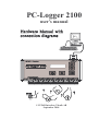
PC-Logger 2100
user’s manual
© INTAB Interface-Teknik AB
September 2004
CONTENTS
1
2
3
4
5
6
7
OVERVIEW............................................................................................... 1
1.1 On-line and Off-line recordings.......................................................... 2
1.2 Memory Capacity during On-line and Off-line recordings ................ 2
1.3 Functional Block Diagram .................................................................. 3
1.4 Display and Keys ................................................................................ 4
1.5 Power Requirements ........................................................................... 5
ANALOGUE INPUTS / RANGES ........................................................... 6
2.1 Ranges................................................................................................. 6
2.2 Temperature measurements - T/C's..................................................... 7
2.2.1
Ranges and linearization......................................................... 7
2.2.2
Cold Junction Compensation.................................................. 8
2.3 Temperature measurements - Pt100 sensors....................................... 8
CONNECTIONS........................................................................................ 9
3.1 Power Supply ...................................................................................... 9
3.2 Computer............................................................................................. 9
3.3 Connecting Sensors and Transducers ............................................... 10
3.3.1
Differential Inputs................................................................. 11
3.3.2
Common Mode ..................................................................... 12
3.4 Examples........................................................................................... 13
3.4.1
Thermocouples T/C .............................................................. 13
3.4.2
20mA Current Loops ............................................................ 14
3.4.3
Voltage output transducers : ................................................. 16
3.4.4. RTD (Pt100) sensors............................................................. 17
3.5 Common errors when connecting transducers .................................. 18
DIGITAL PORTS - COUNTERS ......................................................... 19
4.1 Counters ............................................................................................ 19
4.1.1
Reset mode............................................................................ 19
4.1.2
Accumulating mode.............................................................. 19
4.2 Digital Inputs .................................................................................... 20
4.3 Digital Output ................................................................................... 20
CONNECT DIGITAL PORTS............................................................... 21
5.1 Switch / Relay on Digital Input ........................................................ 22
5.2 TTL/CMOS signal on digital input................................................... 22
5.3 External relay on digital output......................................................... 23
5.4 Status Led on digital output .............................................................. 23
MISCELLANEOUS ................................................................................ 24
6.1 Reset of the PC-logger 2100 ............................................................. 24
6.2 Controller Program ........................................................................... 24
6.3 50/60Hz Adaption ............................................................................. 24
TECHNICAL DATA / SPECIFICATIONS.......................................... 25
7.1 ANALOGUE DATA ........................................................................ 25
7.1.1
Method of measurement ....................................................... 25
7.1.2
Measurement interval ........................................................... 25
7.1.3
Inputs .................................................................................... 25
7.1.4
Ranges................................................................................... 25
7.1.5
Divisions/Dynamic ranges.................................................... 25
7.1.6
Resolution .............................................................................26
7.1.7
Accuracy ...............................................................................26
7.1.8
Temperature Coefficient .......................................................26
7.1.9
Noise .....................................................................................26
7.1.10 Common mode ......................................................................26
7.1.11 Constant Current Output .......................................................26
7.2 DIGITAL PORTS - COUNTERS .....................................................27
7.2.1
Digital Output........................................................................27
7.2.2
Pulse Inputs and Digital Inputs (at 25°C +/-10°C) ..............27
7.2.3
Auxiliary voltage output : V-Out ..........................................27
7.3 INTERNAL DATA STORAGE CAPACITY...................................27
7.4 COMPUTER INTERFACE ..............................................................28
7.5 POWER REQUIREMENTS .............................................................28
7.5.1
Built-In NiCd-accumulators..................................................28
7.5.2
Mains Adapter.......................................................................28
7.6 MECHANICAL ................................................................................28
8
Questions and Answers............................................................................30
INDEX ...................................................................................................................31
1
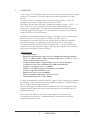
OVERVIEW
A "PC-logger 2100" together with our software and a personal computer running
Windows, constitutes a versatile and powerful data acquisition/recording
system.
PC-logger 2100 is a complete logger useful for many purposes. It will, for
example, easily replace/outdate any strip chart recorder.
The logger measures the full range of industrial analogue signals: +/-10V, +/-1V
and +/-20mA. It is also possible to directly connect thermocouples for
temperature measurements. Cold Junction compensation and linearization are
internally handled by the logger. It is also possible to measure temperature by
means of RTD's (e.g. Pt100 sensors).
In addition to the analogue inputs the logger is equipped with 3 counter inputs.
These can be used for event (pulse) counting, e.g. flow, rpm, etc.
Recordings can be made directly to the storage media on the host computer
(On-line recordings) or temporarily to the internal memory in the logger.
(Off-line recordings) During Off-line recordings there is no need for the host
computer to be connected to the logger. This way the computer can be used for
other purposes during off-line recordings.
Main features
- 8 analogue inputs.
- Range and measurement type are user configurable through software.
(10V, 1V, 100mV, 50mV, 20mA, Thermocouple type: J, K, R, S, T, E,...)
- 16 bit resolution AD converter.
- 3 counter inputs. (plus 3 digital inputs and one Alarm Output.)
- Constant current source suitable for Pt100 measurements.
- On-line recording directly to computer.
- Off-line recordings using internal memory of 224KB.
- Voltage output for transducers etc.
- Display and keys for easy handling.
- Fully compatible with Intab's "EasyView Pro"
- Small dimensions: 250 x 110 x 40mm.
To fully understand the potential of the PC-logger 2100 we strongly recommend
the studying of this entire manual with emphasis on chapter 3 which describes
how to connect sensors and transducers.
How the PC-logger is handled using our software and a PC is explained in the
program manual and by the program itself through its user-friendly and selfexplanatory menus.
Those users who intend to write their own software to collect data are
recommended to obtain the "Command Manual" that describes available
commands and their syntax.
Page 1
1
OVERVIEW
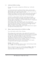
1.1
On-line and Off-line recordings
PC-logger 2100 can make recordings in two different ways: On-line and
Off-line.
An On-line measurement is performed with the computer connected to the
logger during the entire recording. Measured data are continuously transferred
from the logger to the computer and stored on disk.
During the recording it is also possible to analyse/evaluate the measurements in
real-time on the computer screen. You can also analyse previously acquired
recordings while the current recording is taken care of in the background.
An Off-line recording should be initiated by transferring measurement
parameters from the computer to the logger. These parameters tell the logger
how to perform its recording and contain information about: interval, active
channels, channel configuration, etc. (See also software manual.) All parameters
are valid until a new set is transferred.
The PC-logger can then, after the parameters have been transferred, be
disconnected from the computer. The recording is started using the keys on the
logger itself. During the recording, the data is stored in the logger's internal
memory which has a capacity of appr. 110.000 values.
When the recording is completed the logger is again connected to the computer
for transferral of collected data to disk.
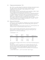
1.2
Memory Capacity during On-line and Off-line recordings
Every stored sample occupies 2 bytes of memory.
When making On-line measurements, it is the amount of free space on the
computer's disk (floppy disk or hard disk) that limits the length of the recording.
For an Off-line recording the limiting factor is the internal memory capacity of
the logger. This memory of 224k Bytes can hold 112 000 values.
The parameters that affect the maximum recording length (or duration) are:
Sampling Interval, Reduction Factor (Averaged Value), Number of channels
used and of course if it is an On-line or Off-line recording.
When using Intab's software, the user is always informed of how long the
recording can last while entering the various parameters.
Example: Off-line-recording.
The PC-logger can sample on 8 channels, 10 times each hour during 2 months.
(0,1 x 224.000) / (2 x 8) = 1400 hours! (58 days)
Please note that the PC-logger only can handle one recording at a time. If an
Off-line recording is started before the previous Off-line recording was
transferred to disk, the first one will be lost!
Page 2
INTAB Interface-Teknik AB, Sweden
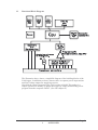
1.3
Functional Block Diagram
The illustration above shows a simplified diagram of the building blocks of the
2100-logger. In addition to what is shown, there is separate power input and an
auxiliary voltage output for supplying sensors.
Note that the control program of the 2100 resides in RAM. This makes it a
simple operation to modify or update the logger by simply downloading a new
program from the computer: BOOT. (See also chapter 6)
Page 3
1
OVERVIEW
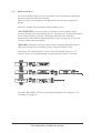
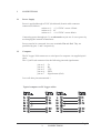
1.4
Display and Keys
An LCD and adjacent keys are incorporated to make it possible to handle the
unit when disconnected from computer.
They are used to start and stop recordings and to check sensor signals and
wiring.
Select one of three main functions using up/down arrows.
"MULTIMETER" is used to check correctness of sensor signals. Scroll
between channels with up and down arrows. The upper line of the display shows
sensor output voltage or current. The bottom line shows the (linearly)
transformed value with the engineering unit you have assigned to it. (See also
"x-form" in the software manual.)
"RECORD" should be selected to stop or start recordings. Remember that a
start erases the previous recording, so don't forget to transfer it first.
The display has a built in lamp. Turn it on and off with the lamp key. To
conserve power it will automatically be turned off after about 15 seconds.
Note that "RECORD" will also contain the information "Recording on" if a
recording is in progress.
Page 4
INTAB Interface-Teknik AB, Sweden
1.5
Power Requirements
The "2100 PC-logger" is normally powered by the supplied mains adapter. It
supplies 12V at a max of 500mA.
The 2100 is fitted with internal rechargeable batteries. They will give the user at
least 8 hours of continuous operation without mains supply when fully charged.
These batteries are trickle-charged by the mains adapter.
There is no danger of overcharging the batteries. They should be left on
charge even if the "2100" isn't to be used for a long time. This will prolong
battery life and ensure fully charged batteries at all times.
Batteries should be replaced at least once every four years.
Some applications require the PC-logger to be powered by other sources. Use a
cable fitted with a "TA3F" (Switchcraft) connector to connect to, for example, a
car battery.
The logger will "fall asleep" about 2 minutes after the last command or keystroke has been entered. This property saves the power in the rechargeable
batteries for when it is needed.
Incoming serial (RS-232) commands or pressing the "C"-key will wake the
"2100".
The built in real time clock will wake the logger in time for every sample if a
recording is in progress.
EasyView Pro automatically supplies the right time to the logger. Make sure that
your computer has the correct time.
Page 5
1
OVERVIEW
2
ANALOGUE INPUTS / RANGES
All analogue channels are DIFFERENTIAL. They measure the voltage between
- and GND and the voltage between + and GND. The subtraction is then
performed internally.
Standard inputs are balanced. This makes them very insensitive to noise if the
signal source is correctly connected. A signal cable consisting of a twisted pair
can be very long if the lowest potential of the source is connected to ground via
a separate cable.
Each channel is individually programmable. It can via the software be set to
measure voltage, current or temperature (thermo emf). The range (=sensitivity)
for each unit (voltage, current, temperature) is also programmable.
This versatile property can be compared to the rotary switch on an ordinary
multimeter with the difference that the user has to press a few keys on the
computer instead (see software manual).
Several types of T/C´s can be employed in the same recording and still be
correctly linearized.
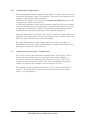
2.1
Ranges
There are approx. 25000 divisions of each range. To put it in other words: each
range has a resolution of FS/25000.
Here is a table of main ranges and their resolutions:
RANGE
+/- 10V
+/- 1V
+/- 100mV
+/- 50mV
+/- 20mA
RESOLUTION
400 µV
40 µV
4 µV
2 µV
0.8µA
Each channel has an internal shunt (51ohms) that is used to measure current. It
must be connected manually via an external jumper in the screw terminal (see
Section 3.4.2.)
NOTE that the shunt will overheat if subjected to more than 80mA.
Page 6
INTAB Interface-Teknik AB, Sweden
2.2
Temperature measurements - T/C's
The "2100" is specially adapted for temperature measuring using thermocouples.
The high resolution of the A/D converter makes it possible to record
temperatures in excess of 1000°C with a resolution of 0.1°C using
thermocouples of type "K".
Thermocouples are active sensors that don't require powering to supply a signal.
They are highly non-linear but are linearized by the "2100".
A thermocouple is, in its simplest form, a pair of wires of dissimilar metals that
are soldered together at one end. The other end is connected to the two screw
terminals of a channel. The difference in temperature between the soldered end
and the screw terminals gives rise to a voltage that can be measured.
This voltage is different for different thermocouple materials. Simply "tell" the
software which type(s) you are using by specifying J, K, T; S, R or ...etc. for
each channel before starting a recording.
2.2.1 Ranges and linearization
Different types of thermocouples have differing levels of output. They therefore
have differing fields of application most often depending on the temperature
range to be measured.
What two materials make up the couple may also be of a certain importance. We
will however have to assume that this is known to the user.
Below is a short summary of the properties of the most common types of
thermocouples. It is included to help in selecting type and range for your
application. "K" is the most common type.
"Cold Junction" = 0°C
TYPE
K
J
T
S
R
mV at
200°C
8.137
10.777
9.286
1.440
1.468
mV at
600°C
24.902
33.096
--------5.237
5.582
mV at
1200°C
48,828
------------------11.947
13.224
MAX temp °C
1370
760
400
1760
1760
Thermocouples are highly un-linear. This is corrected by the internal program of
the "2100".
Thermoelectric voltage is measured (in mV) and then adjusted for the cold
junction temperature according to the type specified. This adjusted voltage is
then used as input variable to a linearizing table. The table (one for each
thermocouple type) is constructed so that its contribution to the measurement
error is negligible.
(+/-0.05°C for T<250°C; +/-0.15°C for T>250°C and "K"-type)
Page 7
2
ANALOGUE INPUTS / RANGES
2.2.2 Cold Junction Compensation
When using thermocouples to measure temperature it is almost always necessary
to know the temperature of the "cold junction". Thermoelectric voltage has to be
"adjusted" with respect to this temperature.
Thermoelectric voltage is the result of the temperature difference between the
"cold junction" and the "hot junction".
A solid state temperature sensor has been placed centrally in the screw terminal
area of the analogue board. Its temperature is automatically sampled every time
a temperature measurement is taken. All temperature measurements are thus
compensated for the actual temperature of the terminals themselves.
Some precautions have to be taken if the "2100" is exposed to rapid temperature
gradients. Since temperature is measured in one point only, a gradient from one
side of the unit to the other may cause misreadings.
By giving the unit time to reach a stable temperature before recordings are
started and by protecting it from sudden changes of ambient temperature a very
high degree of accuracy can be achieved.
2.3
Temperature measurements - Pt100 sensors
The "2100" can also take temperature readings from a Pt-100 sensor. This is
achieved by conventional four wire resistance measurement technique.
A constant current is passed through the sensor via one pair of wires. The
voltage developed across the resistor ( a Pt-100 is a temperature dependent
resistor ) is measured by a channel via the second pair of wires.
The constant current is available at terminal "I-out" on the left-hand side of
channel 1. Several Pt-100´s can be connected in series to the same current
source. ( See next chapter ).
Page 8
INTAB Interface-Teknik AB, Sweden
3
CONNECTIONS
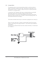
3.1
Power Supply
Power is applied through a TA3F (Switchcraft) female cable connector
connected as follows: .
socket no. 1: + 12-15VDC at max 150mA
socket no. 2: 0V
socket no. 3: + 10-15VDC at max 80mA
Connecting power through pin 3 is an alternative to pin one. It saves power by
not charging the internal accumulators.
Power can also be connected via screw terminals Vin and Gnd. They are
paralleled by pins 3 and 2 respectively.
3.2
Computer
The PC-logger 2100 connects to a serial port of a computer via supplied spiral
cable.
The 15 pin D-sub connectors has the following pins and signal names:
pin no. 2
pin no. 3
pin no. 5
pin no. 6
pin no. 7
:
:
:
:
:
Tx
Rx
CTS
DTR
Signal return (Gnd)
Leave all other pins unconnected.!
Typical computer-to-PC-logger cables:
Page 9
3
CONNECTIONS
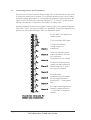
3.3
Connecting Sensors and Transducers
Several years of experience has shown us that 95% of all problems are the result
of erroneous connection of sensors. To avoid measurement errors, noise pickup
and other strange phenomena, it is of paramount importance that all sensors and
signal sources be correctly connected. Chapters 3.3, 3.4 and 3.5 of this manual
must be considered a “compulsory curriculum” to achieve this.
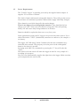
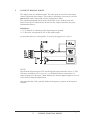
Sensors, transducers and process signals connect to the screw terminal along the
side of the "2100". All screw terminals are detachable. Terminal assignment and
polarity are also printed along the side, see illustration below.
P1, P2 and P3 are digital and
counter inputs.
V-In is auxiliary PSU input
V-Out is an auxiliary
voltage supply for
transducers.
I-Out is a constant current
source (0.500mA) for fourwire resistance
measurements (f.ex. Pt100)
To measure 20mA process
signals you must connect a
jumper between "I" and "+"
on respective channel.
For differential
measurements you connect
the two signals between
ground and "+", and ground
and "-".
For single ended signals you
connect a jumper between
"-" and "Gnd" of respective
channel.
Page 10
INTAB Interface-Teknik AB, Sweden
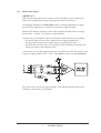
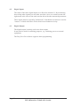
3.3.1 Differential Inputs
OBSERVE !!!
When connecting signals from sensors and/or transducers some simple rules
about referencing them to logger signal ground must be followed.
All analogue channels are differential with a very high impedance to signal
ground. Their inputs have no internal connection to signal ground.
Differential channels measure (as the name implies) the difference in voltage
between the + and the - in relation to signal ground.
Another way of saying this is that each channel really measures two voltages:
- the minus input measures the voltage between signal ground and "-";
- the plus input measures the voltage between signal ground and "+";
- the difference between these two voltages is then calculated internally and
finally presented as the channel value.
A third way is to say that signals must never be allowed to float electrically with
respect to signal ground of the "2100". They must in some way be connected!
The figure above shows one input channel. Note that the ground sign point is
common to all circuitry and channels.
Page 11
3
CONNECTIONS
3.3.2 Common Mode
To maintain accuracy in your measurements you have to make sure that no
signal is outside the common mode range. The difference signal that is to be
measured may not have a common voltage with respect to signal ground that
exceeds 10V (see figure below)
A sensor that is left "floating" with respect to signal ground may easily drift
outside this range because of leakage voltages or static electricity.
This will result in, to say the least, unpredictable measurements, but will not
damage the inputs as long as they are within 30 Volts from signal ground. (see
also technical data: Max overvoltage).
(The shield of shielded cables may be connected to signal gnd at one end only!)
Those users who always have "floating" signals should "ground" all negative
inputs by connecting a short jumper between "-" and "Gnd" of the terminals of
each channel.
It should also be pointed out that water must, almost invariably, be considered to
be a conductor.
Page 12
INTAB Interface-Teknik AB, Sweden
3.4
Examples
Below follow a few examples of how to connect different sensors and signals to
the "2100".
It is always a good idea, not to say good practise and a sign of competence, to
first draw a schematic diagram of how sensors are to be connected to the PClogger and how they may be interconnected. This will save a lot of time by
avoiding common pitfalls like reversed or mixed-up leads, ground loops and
floating signals.
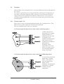
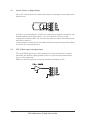
3.4.1 Thermocouples T/C
There are two ways of connecting thermocouples. See examples below. They
differ in the way the signals are referenced to signal gnd.
The two methods can of course be combined.
1) Thermocouple hot junction in contact with conducting object :
Connect object to be
measured to PC-Logger
signal ground via a
separate lead. One lead
is enough for all
channels monitoring the
same object: Gnd is
common to all channels.
(Remember?)
Examples: Water
temperature at several
places in a large vessel ;
several thermocouples
along a metal pipe.
2) Thermocouple hot junction in contact with non-conducting object :
To prevent the measured
signal from "floating
away", each sensor "-"
must be jumpered to
signal "Gnd".
Examples: Measuring air
temperature or plastic
container surface
temperature.
Page 13
3
CONNECTIONS
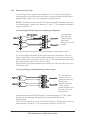
3.4.2 20mA Current Loops
Current loops can be connected in a number of ways. They are basically the
same but appear to be different because they are powered and/or referenced to
gnd differently. Below are a few examples with illustrations.
NOTE : The shunt resistor must for current measuring be manually connected
via a small jumper (=short wire) between "I" and "+". See schematic diagram of
inputs in section 3.3.1.
1) Connecting current loops with common ground points:
Avoid ground
loops by only
connecting the
gnd of one
channel to system
ground.
NOTE! Ground loops can give rise to considerable measurement errors !
Try to keep other instruments in the source path of the transmitter. This will
make it impossible to exceed the common mode range. You can of course also
connect them in the return path ( ground side ) if you make absolutely sure that
the common mode range (10V) isn't exceeded.
Add resistances of inserted instruments to make sure. The sum may not exceed
10V/20mA=500Ω !
2) Connecting ungrounded (floating) current loops:
Give all floating
current sources a
ground reference by
shorting the
negative inputs to
"2100" signal
ground with the help
of a short piece of
hook-up wire.
Again it must be stressed that "floating" is meant in respect to "2100" signal
ground, not any other ground that may be lying around (like safety
earth/ground)!
This, of course, also does not necessarily mean that it is floating with respect to
other grounds! Confused? - Get an electronics engineer to help you!
Page 14
INTAB Interface-Teknik AB, Sweden
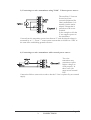
3) Connecting two wire transmitters using "2100" V-Out as power source:
The auxiliary V-Out can
be used to power
external equipment like
20mA transmitters. It is
actually just the mains
adapter voltage that is
passed on to the screw
terminal.
In the example at left the
V-out supplies power to
the transmitter.
Current from the transmitter passes into shunt at "I" and developed voltage is
measured by at "+". From "-" comes return current that is fed back to "Gnd" at
the same time establishing ground reference.
4) Connecting two wire transmitters with external power source:
Two wire
transmitter may
sometimes require
higher voltages to
work properly. In
those cases you
must use an external
PSU.
Connection follows same rules as above but the V-Out is replaced by an external
supply.
Page 15
3
CONNECTIONS
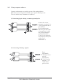
3.4.3 Voltage output transducers
Connect each transducer according to one of the methods below.
Which one you use depend on whether your signal is floating or not.
The two methods may of course be combined.
1) Connecting signals having a common ground point:
Connect the sensor
common ( or ground ) to
"2100" ground at one of
the channels.
If you connect more
than one you will create
a "ground loop" which
may be detrimental to
your measurements.
("Gnd" for all channels
are really the same point
with several
connections !)
2) Connecting "floating" signals:
Each
individually
"floating" source
must be
referenced to
"2100" Gnd by
shorting "-" to
"Gnd" with a
piece of wire.
Page 16
INTAB Interface-Teknik AB, Sweden
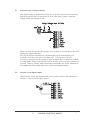
3.4.4. RTD (Pt100) sensors
Using the built-in (I-Out) constant current source (0.500mA) and "four wire technique"
it is easy to measure resistance. In a Pt100, resistance varies with temperature. The
relationship between temperature and resistance is very nearly linear.
Several Pt100 sensors can be connected in series to the same current source. See figure
below.
Channels that are to measure temperature using Pt100 sensors should be set to
FS=100mV.
Resistance is calculated from read voltage by R = U / 0.5mA. (This is a linear
transformation that is extremely easy to realise using the "transform" function of the
software)
A Pt100 has a nominal resistance of 100Ω at 0°C. Resistance then increases by
approximately 0.39Ω/°C. The Pt100 is slightly non-linear so for more accurate
readings the linear transform should be applied around the temperature-points of
interest.
For large swing readings with great accuracy, a polynomial (e.g. the Callendar-van
Dusen equation) for calculation of temperature from resistance should be employed.
Page 17
3
CONNECTIONS
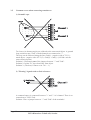
3.5
Common errors when connecting transducers
1) Ground Loops
Two bare wire thermocouples are soldered to the same metal object. A ground
loop results because "Gnd" of both channels are connected to "-".
The loop can be followed along the line: Gnd(1) - negative side of T/C(1) metal object - negative side of T/C(2) - Gnd(2) - Gnd(1). (All Gnd:s are the
same electrical point)
Solution 1: Disconnect one of the jumpers between "-" and "Gnd".
Solution 2: Isolate T/C tips electrically from object.
Solution 3: (The best) Connect as in 3.4.1. : 1)
2) "Floating" signals with no Gnd reference :
A common battery is connected between "+" and "-" of a channel. There is no
connection to "2100" Gnd.
Solution : Place a jumper between "-" and "Gnd" of the terminals!
Page 18
INTAB Interface-Teknik AB, Sweden
4
DIGITAL PORTS - COUNTERS
The "2100" has, in addition to the 8 analogue inputs, three digital ports. These
ports, called P1, P2 and P3, have their main use in pulse-counting applications.
P1 can also be programmed as an output for alarm related purposes.
Pulse counting channels have channel numbers 25 to 27.
Digital inputs appear in channel 31 as one digital bit per input: P1=bit0,
P2=bit1, P3=bit2. The numeric value is the sum of the binary weights of the
three bits.
The digital output is reflected in channel 32. It has the value 0 for a non-active
output and 1 for an active output.
This rather strange channel numbering is the result of our effort to keep it
compatible with PC-loggers 3100i and 3150i.
4.1
Counters
Flow sensors that output an electric pulse for every unit volume that has passed
it are a perfect match for these inputs. By noting counter value and resetting it
every ∆t you get a very exact figure for flow.
Flow, as you well remember, is volume per time, or litres per ∆t, or litres per
minute or ...
Each counter can count up to 65535 then it wraps around and starts at 0 again.
You have to make ∆t short enough so that this doesn't happen.
The counters have two basic modes of operation: Reset mode and Accumulating
mode.
4.1.1 Reset mode
By "Reset mode" we mean the "flow measuring" mode mentioned above. The
counters are read and reset in the same operation every ∆t.
Counters appear as if they were analogue channels showing pulses (or litres or..)
per ∆t.
4.1.2 Accumulating mode
In Accumulating mode the counters are read every ∆t but not reset. The stored
value can then be looked upon as the integral from the time of the start of the
recording up to the "present".
Page 19
4
DIGITAL PORTS - COUNTERS
4.2
Digital Inputs
The status of the three digital inputs are reflected in channel 31. By monitoring
these along other signals you can make sure that valves or switches assume the
right status at the correct time and correlate this with other measured parameters.
These inputs must be externally "debounced" if mechanical switches are used as
"sensors" or fitted with filters if the electrical environment is noisy.
4.3
Digital Output
The digital output is mainly used as an alarm output.
It may also be used for switching purposes, e.g. switching power to external
equipment.
The EasyView Pro software supports alarm programming.
Page 20
INTAB Interface-Teknik AB, Sweden
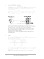
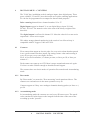
5
CONNECT DIGITAL PORTS
The digital ports are multifunctional. The same pins are used for status input,
counter input and alarm output. This makes it absolutely necessary to exercise
utmost care when connecting external equipment to them.
The schematic diagram below shows the details of one of these ports (P1).
Ports P2 and P3 are identical but do not have the output transistor (the parts
within dashed lines).
Definitions:
A "1" is defined as a shorting of the input/output to ground.
A "1" therefore corresponds to 0V on the input/output.
An unconnected port, consequently, is seen by the logger as a 0 (zero).
NOTE!
Note that the digital output of P1 has the digital output transistor across it. This
will cause contention if it is set to a 1 (see definition above) when there is a
signal coming in to the input. Make doubly sure that the digital output is set to 0
(zero) before using the digital input.
Also note that the 10nF capacitor limits the frequency response of the input to
1000Hz.
Page 21
5
CONNECT DIGITAL PORTS
5.1
Switch / Relay on Digital Input
NO or NC contact devices for status indication or counting are best connected as
shown below.
If need be, you can debounce switches by connecting a capacitor externally. (See
dashed capacitor in the figure above.) A 0.1uF capacitor will give a time
constant of 10 milliseconds, 1uF increases the time constant to 100 milliseconds
and 10uF to about 1s.
Contact bounces usually die down within 100ms but may last longer than 200ms
if contacts are extremely bouncy.
5.2
TTL/CMOS signal on digital input
TTL and CMOS signals are easily connected. No special interface is needed.
Just make sure that the signal grounds of the two systems interconnected this
way are also connected.
Make sure that all signals are below the absolute maximum of 20V.
Page 22
INTAB Interface-Teknik AB, Sweden
5.3
External relay on digital output
The digital output is designed as a relay driver. It will activate an external relay
that in its turn will start an alarm bell or siren. The relay is easily connected.
Simply follow the diagram below.
Make sure that the current I-Rel doesn't exceed 100mA. Currents above this will
damage the output transistor.
The expert engineer immediately calculates this to also mean that the coil
resistance of a relay may not be less than 150Ω if it is powered by 15V.
If a relay is connected to the output as in the example above it must have a built
in clamp diode. Some relays don't have this. In those cases you must connect one
yourself. Observe polarity when connecting it and make sure it can withstand at
least twice the relay voltage and carry a current of at least 200mA.
5.4
Status Led on digital output
Shown below is how the digital output can be used to switch a led indicator on
and off. V-Out is used to supply power.
Page 23
5
CONNECT DIGITAL PORTS
6
MISCELLANEOUS
6.1
Reset of the PC-logger 2100
The PC-logger model 2100 can be reset by temporarily shorting sockets 7 and 8
of the 15 pole D-sub connector.
Resetting the logger will result in it loosing its internal controller program, all
measurement parameters and all measurement data it may have stored.
Its internal controller program must then be re-booted and new parameters
supplied before recordings can be started again. See also next section.
There should never really be any need to reset the "2100" at all.
Only very heavy electrical and RF interference may make it loose track of its
internal controller program and necessitate a reset and subsequent re-boot.
If you think it needs a reset because measurements are "off", it is more than
likely that you yourself have made a mistake in connecting signals. Check
connections instead!
6.2
Controller Program
The internal controller program of the "2100" is stored in RAM (Random
Access Memory). This makes it possible to reload (boot) it if it lost due to a
reset. It is also very simple to up-date or up-grade the "2100" with new or
customised controller programs by simply downloading them by booting from
the software. Booting is done by having the "2100" connected to the correct
serial port of your computer. Please see the software manual on how to BOOT.
6.3
50/60Hz Adaption
The PC-logger family all (except "f" models) have some sort of integrating A/D
converters. As you know, the time integral of a sine wave that is symmetrical to
zero has the exact value of zero if integrated for exactly one period.
In practise this means that all interference from mains is effectively filtered from
the measured signal.
The default setting is for 50Hz mains environment. For countries with 60Hz
mains, like the US, the unit has to have its integration time changed from 20ms
to 16.667ms.
This is easily achieved by, in the software, entering the EasyTerm "terminal
emulator", (see software manual) and then typing the command
HERZ:60[Enter].
(Don't forget to connect the logger to the computer first.)
If you aren't sure what setting you have, you may ask: HERZ:?[Enter].
Go back to Europe and revert to 50Hz setting by: HERZ:50[Enter]
Page 24
INTAB Interface-Teknik AB, Sweden
7
TECHNICAL DATA / SPECIFICATIONS
7.1
ANALOGUE DATA
7.1.1 Method of measurement
∆- -conversion.
7.1.2 Measurement interval
Programmable in 1s steps - min 1s
All channels are sampled with the same ∆t
All channels sampled within the same second.
7.1.3 Inputs
8 differential inputs.
Impedance :
Min 400kΩ between + and Min 5MΩ to ground reference
Overvoltage protection:
30V continuous at voltage input.
Max input current:
80mA continuous at shunt (current) input.
NOTE
Current input shunts are 51Ω resistors.
7.1.4 Ranges
Four voltage ranges and one current range are available on all channels
+/- 10V;
+/- 1V;
+/- 100mV;
+/- 50mV;
+/- 20mA; (*)
Each channel has an associated current shunt (51Ω)
It is connected by jumpering "I" and "+" in the detachable screw terminal.
(*) NOTE : Max allowed current is 80mA
7.1.5 Divisions/Dynamic ranges
All ranges resolve to approximately +/-25 000 divisions.
The ADC has a resolution of +/-15 bits.
The smallest discernible input change is calculated by FS/25000.
The 10V range has an approximate resolution of 10/25000=0.4mV.
Page 25
7
TECHNICAL DATA / SPECIFICATIONS
7.1.6 Resolution
10V
1V
100mV
50mV
20mA
0.4mV
40µV
4µV
2µV
0.8µA
Thermo emf 50mV FS:
T/C J
T/C K
T/C T
T/C S
T/C E
0.1°C
0.1°C
0.1°C
0.3°C
0.1°C
7.1.7 Accuracy
(at 25°C)
Voltage ranges
20mA range
"Cold Junction"
10V
1000mV
100mV
50mV
20mA
+/-(100ppm + 2 divs.)
+/-(200ppm + 2 divs.)
+/-(300ppm + 2 divs.)
+/-(400ppm + 2 divs.)
+/-(300ppm + 2 divs.)
+/-0.5°C
7.1.8 Temperature Coefficient
Ambient temperature variations affect readings by max 50ppm/°C.
7.1.9 Noise
Maximum noise level at +/-15 bit resolution is +/-1 bit (=division)
Use averaging to filter noisy signals.
The "Math" section of the PC-logger software can, using simple formulas, apply
digital filters to noisy signals.
7.1.10 Common mode
Common mode range at FS range 10V
Common mode range all other ranges
CMRR: (dc)
min +/- 5V.
min +/- 10V.
min 80dB
7.1.11 Constant Current Output
The constant current output supplies 0.500mA into loads of a maximum of 5kΩ.
Accuracy
+/-0.2% at 25°C.
Tempco
max 50ppm/°C
Page 26
INTAB Interface-Teknik AB, Sweden
7.2
DIGITAL PORTS - COUNTERS
7.2.1 Digital Output
Output:
Output type:
Max current:
Max voltage:
1; Paralleled by digital input no. 1
Open collector with passive pull-up (100kΩ) to 5V
100mA. (at 25°C +/-10°C)
20V (at 25°C +/-10°C)
7.2.2 Pulse Inputs and Digital Inputs (at 25°C +/-10°C)
No of inputs
"Low" logic level
"Hi" logic level
Max input voltage
Max pulse freq. (*)
Max pulse freq. (*)
Max pulse freq. (*)
Min pulse width
Max counter reading
:
:
:
:
:
:
:
:
:
3 (no.1 paralleled by digital output)
Max 0.8V
Min 3.5V or open ( internal pull-up)
20V
Min 65kHz at 5V in and 50% duty cycle
Min 30kHz at 10V in and 50% duty cycle
Min 20kHz at 15V in and 50% duty cycle
Max 15µs
65.535
(*) With a passive sensor output (open collector, relay contacts, switch contacts
etc.) the maximum input frequency is limited to 1000Hz by the 10nF capacitor
on the input.
7.2.3 Auxiliary voltage output : V-Out
Voltage:
Current:
10-18V derived from connected mains adaptor
Max 200mA with supplied mains adaptor.
Max 1A other external power source.
Note: V-Out is active only when the PC-logger is "awake".
When off line recordings with long sampling intervals are in progress, the
"2100" falls asleep between samplings. This means that power via V-Out is
switched on a few seconds before the sample is taken and then switched off
again as the "2100" goes back to sleep.
7.3
INTERNAL DATA STORAGE CAPACITY
The PC-logger 2100 can store in excess of 112 000 values (off-line).
The data RAM is backed up by a lithium battery that will retain data in case of
power failure.
Lithium battery life is 10 years.
Page 27
7
TECHNICAL DATA / SPECIFICATIONS
7.4
COMPUTER INTERFACE
Computer communication is in serial form.
The serial standard is a subset of RS-232.
Format:
8 bit ASCII, 1 Start bit, 1 Stop bit, No parity bit
Baud rate:
9600 Baud
7.5
POWER REQUIREMENTS
Voltage:
12-18V DC (*)
Current:
ca 60mA (charging current 35 mA)
Current w/o charging batts. :
ca 25mA
(Power via Vin or pin 3 of the TA3F connector. Voltage requirement in this case
is 10V.)
NOTE! With the display back-light on, the current consumption increases by ca
130mA.
(*) At elevated input voltages (>15V) the temperature inside the "2100" rises.
This affects measurement accuracy. (See also temperature coefficient).
7.5.1 Built-In accumulators
Charging time:
ca. 24 hours for full capacity.
Should be left on charge even when not to be used for
longer periods
At least 8 hours continuous operation with fully charged
accumulators.
Capacity:
7.5.2 Mains Adapter
Voltage:
Current:
7.6
12-18V
Min 250mA
MECHANICAL
Length:
Height:
Width:
Weight:
247mm
110mm
36mm
1.1kg
Page 28
INTAB Interface-Teknik AB, Sweden
We believe the information in this manual to be correct. Should there arise
questions about the validity or meaning of information herein we appreciate if
information about this could be forwarded to us.
Because development work continuously improves our products we reserve the
right to make changes without any notice.
In consequence we cannot assume responsibility for any consequential or other
damage resulting from the use of this instrument.
Page 29
7
TECHNICAL DATA / SPECIFICATIONS
8
Questions and Answers
Q: I am recording ambient air temperature using T/C´s type "K" and all values are
jumping up and down. Some values, like -3000°C, are absurd! What causes this?
A: You have forgotten to connect the "-" input to Gnd. Your signal is floating around
without any connection to ground reference. See chapter 3 .
Q: I am logging temperature with T/C´s type "K". The logger indicates a
temperature when I actually lower it. Why is this?
A: You reversed the T/C leads. The red wire is the negative lead.
rising
Q: I am going to log temperature in two places along a metal hot water pipe. Both
thermocouples are welded to the pipe. How do I go about connecting them to the
logger?
A: Since both hot junctions are in contact with a metallic object only one negative lead
should and may be connected to "Gnd". Alternatively you may run a separate wire
from the pipe to "Gnd". All other methods will result in ground loops that may
spoil your measurements.
Q: I want to sample data at the highest possible rate. The memory has to hold data of a
full week.
How do I calculate the shortest possible sampling interval?
A: The memory of the "2100" can hold 112 000 values.
1 week = 604 800 seconds. 604 800 / 112 000 = 5.4 !
Select an interval of 6 seconds for a week long recording on one channel.
You don't really have to make calculations like this. The software will always tell
you how long the memory will last for every set of parameters you program.
Page 30
INTAB Interface-Teknik AB, Sweden
INDEX
5
50Hz, 24
6
Flow sensors, 19
frequency response, 21
G
60Hz, 24
ground loop, 16
ground loops, 14
A
H
Accumulating mode, 19
air temperature, 13
alarm output, 20
hot junction, 8, 13
B
batteries, 5
Block Diagram, 3
boot, 24
Booting, 24
C
car battery, 5
clamp diode, 23
clock, 5
CMOS, 22
cold junction, 8
Cold Junction, 1
Command Manual, 1
Common errors, 18
Common Mode, 12
common mode range, 12
conducting object, 13
Connecting Sensors, 10
constant current, 8
controller program, 24
counter inputs, 10
COUNTERS, 19
Current loops, 14
current source, 8, 17
D
debounce, 22
DIFFERENTIAL, 6
Differential Inputs, 11
differential measurements, 10
digital inputs, 20
Digital inputs, 19
digital output, 19
DIGITAL PORTS, 19
divisions, 6
D-sub, 9
duration, 2
E
errors, 18
F
I
Impedance, 25
integration time, 24
I-out, 8
I-Out, 10
K
keys, 4
L
LCD, 4
linearization, 1
M
mains adapter, 5
MULTIMETER, 4
N
non-conducting object, 13
O
Off-line, 2
On-line, 2
output, 19
output transistor, 21, 23
P
P1, P2 and P3, 10, 19
parameters, 2
Power Supply, 9
Pt100, 8, 10, 17
pulse-counting, 19
R
range, 6
ranges, 25
real-time, 2
RECORD, 4
recording length, 2
relay, 23
relay driver, 23
Reset, 24
Reset mode, 19
resolution, 6
RTD, 17
floating, 12
INDEX
Page 31
S
sample, 2
screw terminal, 10
Sensors, 10
serial port, 9
shunt, 6, 15, 25
SPECIFICATIONS, 25
T
T/C, 13
TECHNICAL DATA, 25
Terminal assignment, 10
thermocouples, 7
Thermocouples, 13
Thermoelectric voltage, 7
transmitters, 15
trickle-charged, 5
TTL, 22
V
V-In, 10
V-Out, 10, 15
Page 32
INTAB Interface-teknik AB Sweden