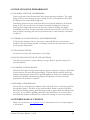
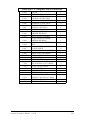
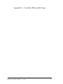
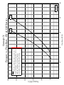
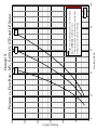
1
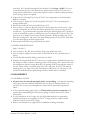
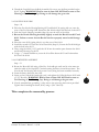
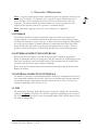
OWNER’S MANUAL Gamajet Cleaning Systems, Inc. 604 Jeffers Circle Exton, PA 19341-2524 United States of America v.8/08 © Gamajet Cleaning Systems, Inc 2008, All Rights Reserved Tel: (610) 408-9940 Toll Free: (877) GAMAJET Fax: (610) 408-9945 E-mail: [email protected] www.gamajet.com TABLE OF CONTENTS 1 - INTRODUCTION ................................................................................... 1 1.1 DESCRIPTION ................................................................................................... 1 1.2 ICONS USED IN THIS MANUAL................................................................. 1 1.3 INSTALLATION OF NEW MACHINES..................................................... 2 1.3.1 ASSEMBLY.......................................................................................................................... 2 1.3.2 INLET CONNECTIONS................................................................................................. 2 1.3.3 MOUNTING....................................................................................................................... 2 1.3.4 LOCATION INSIDE TANK .......................................................................................... 2 1.3.5 ENTRY OPENINGS......................................................................................................... 3 1.3.6 VESSEL DRAINAGE....................................................................................................... 3 1.3.7 FILTERS AND STRAINERS .......................................................................................... 3 1.3.8 CAPACITY OF SUPPLY PUMP .................................................................................... 3 1.3.9 INITIAL STARTUP........................................................................................................... 4 1.4 SAFETY................................................................................................................. 4 2 - DISASSEMBLY, REPAIR, AND REASSEMBLY .................................. 5 2.1 TOOLS REQUIRED .......................................................................................... 5 2.2 GENERAL DISASSEMBLY............................................................................. 5 2.2.1 INLET COLLAR................................................................................................................ 5 2.2.2 NOZZLE HOUSING ....................................................................................................... 5 2.2.3 CAP AND GEAR TRAIN................................................................................................ 5 2.2.4 BODY ASSEMBLY............................................................................................................ 6 2.3 INSPECTION AND SERVICE OF COMPONENTS ............................... 6 2.3.1 STATOR............................................................................................................................... 6 2.3.2 COLLAR O-RINGS........................................................................................................... 6 2.3.3 PLANETARY GEAR TRAIN ASSEMBLY.................................................................. 6 2.3.3.1 General Disassembly and Inspection ..................................................................................................... 6 2.3.3.2 Gearhead Internals .................................................................................................................................... 7 2.3.3.3 Input Shaft and Housings ........................................................................................................................ 7 2.3.3.4 Gearhead Lower Bearing Housing and Output Shaft.......................................................................... 7 2.3.4 NOZZLE HOUSING ....................................................................................................... 8 2.3.5 TEE HOUSING AND TEE HOUSING CAP ............................................................ 8 2.3.6 STEM AND STEM BASE ................................................................................................ 9 Gamajet X Owner’s Manual – v.8/08 i 2.4 REASSEMBLY ..................................................................................................... 9 2.4.1 GENERAL NOTES........................................................................................................... 9 2.4.2 GEAR TRAIN................................................................................................................... 10 2.4.3 BODY ASSEMBLY.......................................................................................................... 10 2.4.4 GEAR TRAIN INSTALLATION................................................................................. 10 2.4.5 NOZZLE HOUSING ..................................................................................................... 11 2.4.6 COMPLETED ASSEMBLY........................................................................................... 11 3 - PREVENTIVE MAINTENANCE ........................................................ 12 3.1 STORAGE........................................................................................................... 12 3.2 EXTERNAL INSPECTION INTERVALS ................................................. 12 3.3 INTERNAL INSPECTION INTERVALS .................................................. 12 3.4 TIPS ...................................................................................................................... 12 4 - TROUBLESHOOTING GUIDE .......................................................... 13 4.1 MACHINE DOES NOT ROTATE .............................................................. 13 4.1.1 INSPECTION FLOW CHART FOR MECHANICAL PROBLEMS ................... 13 4.1.2 INSUFFICIENT FLOW ................................................................................................. 14 4.1.3 TIGHT CLEARANCES.................................................................................................. 14 4.1.4 DEBRIS INSIDE.............................................................................................................. 14 4.2 CLEANING SOLUTION LEAKAGE......................................................... 14 4.2.1 WORN BEARINGS & SEALS ...................................................................................... 14 4.2.2 WORN HOUSING CUPS .............................................................................................. 14 4.2.3 WORN COLLAR O-RINGS.......................................................................................... 14 4.3 POOR CLEANING PERFORMANCE ....................................................... 15 4.3.1 INADEQUATE FLOW AND PRESSURE................................................................ 15 4.3.2 CHEMICAL CONCENTRATION AND TEMPERATURE ................................. 15 4.3.3 PLUGGED NOZZLES .................................................................................................. 15 4.3.4 SLOW OR NO ROTATION OF THE HOUSINGS ............................................... 15 4.3.5 GAMAJET CONFIGURATION .................................................................................. 15 4.3.6 INADEQUATE DRAINAGE....................................................................................... 15 Gamajet X Owner’s Manual – v.8/08 ii 4.4 OWNER’S MANUAL UPDATES ................................................................. 15 APPENDIX A - OPERATING PARAMETERS .....................................A-1 APPENDIX B –SPARE PART LIST ........................................................B-1 APPENDIX C – ASSEMBLY/DISASSEMBLY STEPS..........................C-1 APPENDIX D – PERFORMANCE CURVES ....................................... D-1 FLOW RATE VS. TYPICAL FULL CYCLE TIME ...................................... D-2 PRESSURE VS. FLOW RATE........................................................................... D-3 Gamajet X Owner’s Manual – v.8/08 iii 1 - Introduction 1.1 DESCRIPTION The Gamajet X is a fluid-driven (turbine-driven) 360° rotary nozzle machine designed for cleaning the interior surfaces of a wide variety of process vessels with a minimum opening of 4.00 inches (101.6 mm) in diameter. It is powered entirely by the cleaning solution and it requires no electricity, compressed air or lubricant for operation. The Gamajet X is designed for both portable and CIP (Clean In Place) applications. If the Gamajet X is permanently mounted inside a tank, we strongly recommend inspecting the unit every few hundred hours of operation. (See Section 3 - Preventative Maintenance for more information.) WARNING: Under no conditions, whatsoever, should the Gamajet X ever be immersed in anything, unless you have prior approval from Gamajet Cleaning Systems, Inc. Failure to comply with this restriction will void the warranty!! In order to handle the broadest possible range of applications, the stainless steel Gamajet X is available with an extensive selection of nozzle sizes, stators (non-rotating turbine), and O-ring materials. The nozzles are available in several interchangeable sizes that range from 1/4” to 3/8”. The Gamajet wash cycle time can be adjusted for special applications by changing the stator and/or nozzle size. Interchangeable stators and nozzle sizes are available for either low or high pressures and/or flow rates. The performance capabilities of these options are detailed in Appendix D. A three-view cut sheet of the Gamajet X is contained in Appendix A. 1.2 ICONS USED IN THIS MANUAL Warning! - The information associated with this icon could cause damage to the machine, vessel it is contained within, or the operator. Note - A useful piece of information worth remembering. Assembly/Disassembly Tip - The following information is a tip from Gamajet that will aid you in working on the machine. Gamajet X Owner’s Manual – v.8/08 1 1.3 INSTALLATION OF NEW MACHINES 1.3.1 ASSEMBLY Every Gamajet is operationally tested before shipment and is ready to run after unpacking. No assembly is required prior to use. The Gamajet has been configured to meet the operating conditions (at the Gamajet, not at the pump) given to us, e.g. pressure, flow, temperature, cycle time, chemical adders, etc. Note: Any change to the original operating conditions will affect the Gamajet accordingly. WARNING: Do not force Tee & Nozzle Housing #10-104 & #10-105 to rotate. Doing so will damage internal components. 1.3.2 INLET CONNECTIONS The standard inlet connection for the Gamajet X is a 1-1/2” NPT female. Others inlets are available. It is recommended that when using the pipe thread the mating male thread should be wrapped with PTFE pipe joint tape prior to mounting. This will minimize any chance of leakage and will make subsequent removal much easier. 1.3.3 MOUNTING Before mounting the Gamajet X, make sure the supply line has been adequately flushed. It can be mounted on a rigid 1-1/2” pipe using a pipe wrench. In most applications, the Gamajet X will be mounted with the inlet connection pointing up; however, the X will function at any orientation. In the cleaning of under ground storage tanks, USTs, Gamajet recommends the use of its UST Lance or Hose Insertion Assembly. Either device will ensure a proper insertion depth, sealing of the riser pipe. Also, the UST Lance includes a lanyard loop that provides a means to attach a safety line between the X UST Lance and the safety loop on the X. We do not recommend attaching the machine to a hose while in the inverted or horizontal orientation. This form of mounting is not rigid and, thus, will not maintain the Gamajet’s position should the unit become unbalanced due to clogging of the nozzles. WARNING: When attaching the Gamajet X onto the supply pipe, ALWAYS apply the wrench to the Inlet Collar #10-108 at the top/inlet of the unit. Never use a wrench on Stem #10-103, Tee Housing #10104, or Tee Housing Cap #10-114 to tighten the unit onto the pipe. Doing so risks internally damaging the machine. Refer to Step 21 in Appendix C for an illustration. 1.3.4 LOCATION INSIDE TANK Generally, a single Gamajet will be positioned in the approximate center of the vessel in order to equalize the cleaning radius in all directions. Some vessels, however, may have specific cleaning problems such as coils or heavy deposits such as the liquid level line Gamajet X Owner’s Manual – v.8/08 2 (bathtub ring). In these situations the Gamajet should be located closer to the difficult area for the best cleaning results. Tanks with internal mechanisms or structures such as an agitator shaft, impellers or baffles will require careful positioning to minimize the “shadow” on areas which do not receive direct jet impact. Sometimes, more than one machine, or, more than one placement of a single machine, may be necessary to avoid shadow problems or “striping.” 1.3.5 ENTRY OPENINGS When using the Gamajet X, the vessels being cleaned must provide entry openings large enough to avoid interference during insertion and removal. The minimum opening size required for the Gamajet X is 4.00 inches in diameter (101.6 mm) for free-hand installation. 1.3.6 VESSEL DRAINAGE If it is necessary to clean the floor of a vessel, remember that standing liquid will diminish the effectiveness of the jet by covering any soils underneath. Wherever possible, the tank floor should be pitched toward the drain and the drainage opening should be large enough to eliminate or reduce any liquid buildup or puddling. If gravity alone is insufficient, a scavenger or stripper pump should be connected to the drain to suck out the excess wash fluid. In extreme cases, it may be necessary to use smaller nozzles on the Gamajet, or even to operate it intermittently to allow time for draining. 1.3.7 FILTERS AND STRAINERS All tank cleaning systems should be equipped with a filter or strainer that will trap solids 1/16” and larger, as these will not pass through the Gamajet. These particles can become caught in one of the internal passages of the machine and cause it to stop turning or reduce its cleaning effectiveness due to a loss of flow. It will then be necessary to disassemble the Gamajet and remove the blockage. In recirculated (closed-loop) cleaning, or, any other application where the cleaning solution may carry abrasive solids in suspension, adequate filtration is a must. These particles can be extremely destructive to the Gamajet, pumps, valves, and other system components. Filters, properly installed and maintained, will more than pay for themselves with lower overall operating costs in these applications. Furthermore, to ensure that clogged filters or strainers are cleaned, we recommend using automatic selfcleaning models. 1.3.8 CAPACITY OF SUPPLY PUMP The Gamajet X can be used with either a centrifugal or positive displacement (constant volume), PD, style pump. In most cases, if the X is to be used with a centrifugal pump, the X should be configured so that the pump will operate close to its best efficiency point. The end user must, therefore, take all of the plumbing, elevation, and X pressure/flow rate requirements into account. If a PD style pump (i.e. piston pump, plunger pump, or mechanical diaphragm pump, etc.) will supply the wash fluid to the Gamajet X, a different set or rules apply. PD Gamajet X Owner’s Manual – v.8/08 3 pumps are fixed volume pumps whose flow rate is dependent upon the rotational speed of the pump; the pumps also have a pressure rating which is the maximum operating pressure. Note: Do not confuse the maximum operating pressure of a PD pump with the actual operating pressure, the actual operating pressure is dictated by the fixed flow rate of the pump and the Gamajet X / plumbing system. If a PD pump is used, the Gamajet X should be sized to, first, match the flow capability of the pump and, second, not exceed the X’s or pump's maximum operating pressure (taking the pressure rating of the plumbing system into account, also). WARNING: For high-pressure applications (over 150 psig), the pressure of the system must "ramp up" to its operating pressure. If the system experiences a pressure spike or pressure increases at a rate of more than 150 psi per second, the machine may be damaged and parts will wear out prematurely. Damage resulting from this phenomenon is not covered by the warranty. 1.3.9 INITIAL STARTUP Every X that ships is accompanied by a Birth Certificate. This document indicates how the X performed in our testing tank before it shipped based on the operating conditions supplied to Gamajet. To ensure the longest possible life of the X, please verify the operating conditions and, most importantly, the machine’s cycle time. The cycle time can be measured by, first, picking a fixed point inside of a vessel as a reference and, second, timing how long it takes the same nozzle to pass back over that point in the vessel. (This, naturally, will not be the exact same spot because the spray pattern is indexing.) The measured time in seconds directly corresponds to the machines full cycle time in minutes. In other words, a single 10-second rotation translates to a 10 minute full cycle time. 1.4 SAFETY When a Gamajet is operating, there should be covers over every tank opening. These covers should be sealed well enough to withstand the full force of the jet striking the cover plate. If the cleaning solution were hot, corrosive, or toxic, a leak would present a serious hazard to any personnel in the immediate vicinity or to any exposed electrical equipment. For cleaning of USTs, Gamajet recommends purchasing the optional UST Lance or Hose Insertion Assembly. Each device is specifically designed for sealing against the 4” riser pipe while allowing the supply hose to properly sit at grade level. In either case, a grounding / safety loop is provided on the X for easy attachment of a cable. This will ensure proper dissipation of static electricity and eliminate the possibility of accidental detachment of the X while in the UST. WARNING: Any tank-cleaning machine can develop a static electricity charge while in operation. If the tank being cleaned contains a combustible liquid or vapor having a risk of ignition or explosion, it is imperative to have the Gamajet properly grounded using the provided location on the unit. Gamajet X Owner’s Manual – v.8/08 4 2 - Disassembly, Repair, and Reassembly 2.1 TOOLS REQUIRED Needle Nose Pliers 5/64”, 3/32” and 5/32” Hex Keys (Allen Wrench) Small and ¼” Slotted Screwdrivers #1 and #2 Phillips Screwdriver 11/32” Hex Socket and Ratchet, or, equivalent Nut Driver. Razor Blade Brass Pick Bench Vise (4-6” jaw opening) No. 3 Arbor Press (3 ton) or Hammer Micrometer (0-6” Digital or Dial Calipers) 2.2 GENERAL DISASSEMBLY Notes: The appropriate step(s) in Appendix C is/are indicated at the beginning of each section. Also, for simplicity the “10-” prefix to the part number has been eliminated in all of the following instructions. 2.2.1 INLET COLLAR Step – 21 If used, loosen the Grounding Set Screw, #163, with a 5/64” Hex Key, minimum 2 turns. Remove grounding / safety wire from loop. Loosen the Collar Set Screw #150 with a 3/32” Hex Key, minimum 2 turns. Remove the Inlet Collar #108 and Stator #109. WARNING: Hold or turn on Stem. DO NOT hold or turn on Tee Housing or Tee Housing Cap. Doing so will damage the gear train. 2.2.2 NOZZLE HOUSING Step – 20 Unscrew the Nose Plate Screws #151 with a ¼” slotted screwdriver. Pull the Nozzle Housing (Step 18) from the nose of the Tee Housing. Remove the inner Nozzle Housing Seal #136 and Bearing #133. 2.2.3 CAP AND GEAR TRAIN Step - 15 Using pliers on the flats of the Cap #102, unthread it from the body (Step 14). WARNING: Hold or turn on Stem. DO NOT hold or turn on Tee Housing or Tee Housing Cap. Doing so will damage the gear train. Pull the Gear Train (Step 9) from the remainder of the body. Gamajet X Owner’s Manual – v.8/08 5 2.2.4 BODY ASSEMBLY Step - 14 Unthread the Tee Housing Cap #114 from the Tee Housing (Step 11). Note: This is a Left Hand thread. Remove the Stem Screws #146 with a 5/32” Hex Key, and Stem Base (Step 12) from the Tee Housing (Step 11). Remove the Tee Housing (Step 11) by pulling it from the Stem (Step 10). The upper Tee Housing Seal #135 and Bearing #131 will pull of with the Tee Housing. Remove the lower #135, #131 and Bevel Gear (Step 13). 2.3 INSPECTION AND SERVICE OF COMPONENTS 2.3.1 STATOR Step - 21 Inspect the through holes of the Stator #109 to be sure that they are clear. 2.3.2 COLLAR O-RINGS Step - 15 Inspect the Small and Large Collar O-rings, #7-458-V and #E-862, for damage (clipped or cut) or deterioration (compression set or hardening) and replace if necessary. Inspect the Collar-Stem O-ring E-863 for damage (clipped or cut) or deterioration (compression set or hardening) and replace if necessary. 2.3.3 PLANETARY GEAR TRAIN ASSEMBLY 2.3.3.1 General Disassembly and Inspection Steps – 5 to 9 Turn to Step 9: Pull the Output Shaft #112 from the Planetary Gearhead (Step 7) Unscrew the Rotor Nut #8-545 with an 11/32” socket and remove it with the Lockwasher #8-544 from the gear train. Remove the Rotor #E-810 (Step 8). If needed, use a slotted screwdriver for assistance. Turn to Step 8: Ensure the Carbide #E-839, pressed into #E-810, protrudes slightly, and is not chipped or cracked. Viewing Step 7: Pull and twist the Gearhead Lower Bearing Housing #129 (Step 6) and Input Shaft Upper Bearing Housing #128 (Step 1) from the Gearbox #101 (Step 5). If the Gearbox Seals #E-826 did not come out of the #101 when the #129 and #128 were removed, remove them at this time. WARNING: To reduce the likelihood of scratching any sealing surface, use a pick made from brass. Inspect the #E-826 for loss of spring tension (indicated by excessive dry deposits of dirty or abrasive cleaning solution on the spring), replace as required. Turn to Step 5: Using a #2 Phillips screwdriver, unscrew the Gearbox Screws #E-853 from the Gearbox #101. Remove the Planetary Gearhead (Step 4) from #101 by pushing on its output shaft. Gamajet X Owner’s Manual – v.8/08 6 2.3.3.2 Gearhead Internals Steps – 4, 4a Tip: To prevent the internal components of the Planetary Gearhead from unexpectedly spilling out, make sure that all steps are done with the input side of the assembly facing up. Using a #1 Phillips screwdriver, unscrew the Gearhead Screws #154 from the Gearhead #113. Remove the Input Shaft Lower Bearing Housing #E-827 from the #154. WARNING: If you suspect that the #113 requires service, proceed with caution. If at any time you do not feel completely comfortable servicing #113, contact Gamajet Cleaning Systems immediately. Using a needle nose pliers carefully remove the internal components of the #113. Examine the gears of the four different stages for any worn or broken teeth. Also, examine the main internal ring gear for bent or sharp teeth. If any damage is found contact Gamajet immediately. The gears of the bottom (14 teeth) and top (17 teeth) stages must be reinstalled in their respective locations. The gears in the second and third level (18 teeth) are interchangeable, however. During reassembly, Gamajet recommends the gearhead be lightly repacked using foodgrade grease. Please contact Gamajet for a specific grease recommendation. 2.3.3.3 Input Shaft and Housings Steps – 1 to 3 Turn to Step 3: Inspect the Input Pinion #8-512 for hairline cracks on the end face or for worn, damaged, or sharp/pointed teeth. #8-512 should be tight to the Input Shaft #E-822 and the Input Shaft Washer #E-841. #E-841 should not be able to spin on the #E-822. Press #8-512 back onto #E-822 if it has slipped, or replace if cracked or worn. Check for signs of scoring and wear on #E-822. Replace if the coating has been chipped or cracked. Turn to Step 2: Inspect the Input Shaft Seal #E-867 (inside the Input Shaft Lower Bearing Housing #E-827) for wear by placing the #E-822 back through it. There will be drag if the #E-867 is still good. If it needs to be replaced, pry out the old #E-867 (using a brass pick), and replace it with a new one. Ensure that the seal is as square as possible to the #E-827 when installing it. The internal spring should be up and visible. Tip: Use a soft object, such as a pencil’s eraser, to apply even pressure when installing #E-867. Check the Lower Bearing Housing O-ring #8-539 and Seal #E-823 for deterioration or damage, replace (using a brass pick to remove the old components) if necessary. The #E-823 should be installed so its internal spring is up and visible. Viewing Step 1: The Pin #6-166 should be firmly pressed into the Input Shaft Upper Bearing Housing #128. The carbide #E-839 in the #128 should protrude slightly. In addition, its running surfaces should be smooth, flat, and free of chips and cracks. 2.3.3.4 Gearhead Lower Bearing Housing and Output Shaft Steps – 6 and 9 Gamajet X Owner’s Manual – v.8/08 7 Turn to Step 9: Check the Output Shaft #112 for signs of scoring or wear, especially in the area of contact with the Output Shaft Upper Seal #E-824. Replace if worn. Turn to Step 6: Examine the #E-824 for loss of spring tension (indicated by excessive dry deposits of dirty or abrasive cleaning solution on the spring). Also, ensure that it still has interference with the #112 by passing the #112 through the center of the seal. There will be a noticeable drag if the seal is still good. If the #E-824 must be replaced, remove the Retaining Ring #E-843 using a small slotted screwdriver. Pry out the old #E-843 (using a brass pick), and replace it with a new one. Ensure that the seal is square to the #129 when installing it. The new #E-824 should be installed with the spring facing out and visible after it is installed. Reinstall the #E-843. 2.3.4 NOZZLE HOUSING Steps – 16 to 18 and 20 Turn to Step 18: Unscrew the Taper Cap Screws #153 with a 5/32” hex key. Pull the Nozzle Housing Taper Cap #105-TC from the Nozzle Housing (Step 16) assembly. Inspect the #105-TC for excessive damage. If it is no longer protecting the nozzles, replace it. Unscrew the Nozzles #107 with pliers and inspect for debris caught on the Stream Straightener #160 or in the nozzle orifice. The inside diameter of #107 must be smooth, round, and free of damage (especially any nicks) for maximum jet impact. Replace worn or oversized nozzles if the original flow rate and pressure are required. Verify the #160 is tight in the bore of the #107. Inspect the Nozzle O-ring #643 for compression set or deterioration. Replace, if needed. Turn to Step 16: Inspect the Nozzle Housing Bevel Gear #118 for wear such as sharp/pointed or worn teeth. If it needs to be replaced, remove the Bevel Gear Retaining Ring #119 with a small slotted screwdriver and pry #118 from the Nozzle Housing #105. Clean any deposits from #134 and examine for excessive wear. Light scoring is acceptable, but the #134 should be replaced if they are grooved in the seal contact area. A good maintenance program will require replacing many #134, therefore, it may be worthwhile to make or obtain press tools for pressing #134 out of #105. The press tools are available from Gamajet Cleaning Systems. Before installing new #134, clean the housing bores and remove any burrs resulting from #134 removal. Press them in so that their flanges are flush against #105. Turn to Step 20: Inspect the Nozzle Housing Bearings #133 and Seals #136. Clean any deposits from the exterior of #133 and check their fit in the #134. While they should turn freely, #133 should be replaced if the thickness of the flange is 0.086”, or less, to avoid shortening the life of the Bevel Gears. Inspect the interior of #136 for loss of spring tension (indicated by excessive dry deposits of dirty or abrasive cleaning solution on the spring), replace as required. 2.3.5 TEE HOUSING AND TEE HOUSING CAP Steps – 11, 13 and 14 Turn to Step 14: Check the water outlets on the nose of the Tee Housing #104; they should be free of debris. Inspect the Tee Housing Bearings #131 and Seals #135. Clean any deposits from the exterior of #131 and check their fit in the Tee Housing Cups #132. While they should Gamajet X Owner’s Manual – v.8/08 8 turn freely, #131 should be replaced if the thickness of the flange is 0.095”, or less, to avoid shortening the life of the Bevel Gears. Inspect the interior of #135 for loss of spring tension (indicated by excessive dry deposits of dirty or abrasive cleaning solution on the spring), replace as required. Inspect the Tee Housing Cap O-ring #7-458-V for compression set or deterioration. Replace, if needed. Turn to Step 13: Inspect the Tee Housing Bevel Gear #117 for worn, damaged or sharp/pointed teeth. Ensure that the Pin #164 is pressed firmly into #117. Turn to Step 11: Clean any deposits from #132 and examine for excessive wear. Light scoring is acceptable, but the Cups should be replaced if they are grooved in the seal contact area. A good maintenance program will require replacing many #132, therefore, it may be worthwhile to make or obtain press tools for pressing #132 out of #104. The press tools are available from Gamajet Cleaning Systems. Before installing new #132, clean the housing bores and remove any burrs resulting from #132 removal. Press them in so that their flanges are flush against #104. Ensure that the Pin #164 is pressed firmly into #104. 2.3.6 STEM AND STEM BASE Steps – 10 and 12 Turn to Step 12: The Pin #164 should be firmly pressed into the #130. Turn to Step 10: Inspect the water outlets of the Stem #103; they should be free of debris. The Pin #E-866 should be firmly pressed into the #103. Examine the Output Shaft Seal #7-150 for loss of spring tension (indicated by excessive dry deposits of dirty or abrasive cleaning solution on the spring). Also, ensure that it still has interference with the Output Shaft #112 by passing the #112 through the center of the seal. There will be a noticeable drag if the seal is still good. If the #7-150 must be replaced, pry it out using a brass pick, and replace it with a new one. The new #7-150 should be installed with the spring facing in and not visible after it is installed. 2.4 REASSEMBLY 2.4.1 GENERAL NOTES All parts must be cleaned thoroughly before reassembling. Any deposits remaining on the parts can cause difficult disassembly the next time the Gamajet needs to be serviced. Also, it may cause misalignment of parts and the potential for premature failure. Unless otherwise stated, apply a dab of a Teflon-based anti-seize compound to all threads when reassembling; this will prevent galling of threads and ease any future disassembly. To ease installation of all O-rings, they should be lubricated prior to reassembly. Lithium-based grease is acceptable, for Viton® O-rings, however, a Silicon based lubricant must be used for EP O-rings. Refer to the illustrations in Appendix C for clarification during reassembly. Gamajet X Owner’s Manual – v.8/08 9 2.4.2 GEAR TRAIN Steps – 4, 5, 7 and 9 Turn to Step 4: Insert the Gearbox Screws #154 through the Gearhead #113. Push the Input Shaft (Step 3) through the Input Shaft Lower Bearing Housing (Step 2). While installing the Lower Bearing Housing onto the #113, ensure the Input Pinion meshes properly with the top layer of gears. Using a #1 Phillips, screw the #154 into the Lower Bearing Housing (Step 2). Turn to Step 5: Install the Planetary Gearhead (Step 4) back into the Gearbox #101. After aligning the screw holes, thread the Gearhead Screws #E-853 back into the Gearhead using a #2 Phillips screwdriver. Make hand tight. Turn to Step 7: Install the Gearbox Seals #E-826 into Gearbox (Step 5). The seal’s internal spring should be face out and be visible. Install the Upper (Step 1) and Lower (Step 6) Bearing Housings into the proper ends of the Gearbox (Step 5) by using equal pressure around parts. They will snap into place. Turn to Step 9: Place the Rotor #E-810 (Step 8) over the end of the Input Shaft #E822. Install the Lockwasher #8-544 and Nut #8-545 using an 11/32” socket. Hold the #E810 stationary with a pair of pliers while tightening the #8-545. Place the Output Shaft #112 into the output side of the gear train assembly. Ensure the slot of the #112 is aligned with the flats on the Gearhead’s shaft. 2.4.3 BODY ASSEMBLY Step - 14 Slide the Tee Housing Bevel Gear #117 (Step 13) over the end of the Stem #103 (Step 10). Align the hole in the #117 with the Pin #E-866. Place the first Tee Housing Bearing #131 and Seal #135 (spring side up) onto the #103. Push the Tee Housing #104 (Step 11) over it until it is flush and fully seated. Install the second #135, spring side down, over the #103. Tip: Now, Place the second Tee Housing Bearing #131 into Stem Base #130 (Step 12), aligning its hole with the Bearing Locating Pin #164. Now, invert the #104/#103 assembly and place it over #131/#130 assembly. This technique ensures correct alignment of #131 and #164. Apply pressure to #130 to drive it, #131, and #135 into #104. Align the through holes of the #130 with the threaded holes in the top of the #103. Using a 5/32” Hex Key, thread Cap Screws #146 and Lockwasher #E-847 into the #103. Tighten in a star pattern. Thread the Tee Housing Cap #114 to the end of the #104. Note: This is a Left Hand thread. 2.4.4 GEAR TRAIN INSTALLATION Step - 15 Insert the Gear Train (Step 9) from section 2.4.2 into the Body Assembly (Step 14) of 2.4.3. Rotate the Tee Housing #104 until the Output Shaft #112 falls into the slot of the Tee Housing Cap #114. Gamajet X Owner’s Manual – v.8/08 10 Thread the Cap #102 into the Body Assembly. Be sure to use the flats provided on the #102. Tighten. WARNING: Hold or turn on Stem. DO NOT hold or turn on Tee Housing or Tee Housing Cap. Doing so will damage the gear train. 2.4.5 NOZZLE HOUSING Steps – 20 Place the first Nozzle Housing Bearing #133 and Seal #136 (spring side out) onto the nose of the Tee Housing #104. Ensure the Pin #164 is aligns with the hole in the #133. Push the Nozzle Housing Assembly (Step 18) onto the nose of the #104. Rotate the Nozzle Housing Assembly slightly to mesh the Bevel Gears #117 and #118. Failure to ensure that the Bevel Gears have properly mated could damage them. Place the outer #136 (spring side in) over the nose of the #104. Install the second #133 into the Nose Plate #106 (Step 19). Ensure the Pin #164 aligns with the hole in the #133. Then, using the #106 / #133, push the #136 into the annular space between the #104 and Nozzle Housing Cup #134. Using a ¼” slotted screwdriver, screw the Nose Plate Screws #151 and Lockwashers #152 into the #104. 2.4.6 COMPLETED ASSEMBLY Step – 21 Rotate the Rotor #E-810 using a Hex Key. It should spin easily and its veins must not strike the walls of the Cap #102. Continue turning the Rotor several dozen times. The Nozzle and Tee Housing will slowly rotate if every thing has been assembled correctly. Insert the Stator #109 into the #102. Screw on the Collar #108 (hand-tight only), and tighten the Collar Set Screw #150 with a 3/32” Hex Key. WARNING: Hold or turn on Stem. DO NOT hold or turn on Tee Housing or Tee Housing Cap. Doing so will damage the gear train. If used, reattached the grounding / safety wire to the unit using the location provided. Tighten the Grounding Set Screw, #163, using a 5/64” Hex Key. This completes the reassembly process. Gamajet X Owner’s Manual – v.8/08 11 3 - Preventive Maintenance Note: A rigorously implemented preventative maintenance program will significantly reduce repair costs over the life of the Gamajet. The foundation of such a program is regularly scheduled inspections to discover and replace worn or damaged parts before they can cause the failure of other, more costly, components. The inspection intervals required will depend on the severity of the application, but a complete internal inspection at 100 hours of operation is recommended initially. Note: Part numbers appearing below may be used to identify parts in Appendix C. 3.1 STORAGE The Gamajet should be washed out with clean water after each use to remove any foreign material or soft substances left in the machine that may harden during storage and cause the Gamajet to seize or lock up. A clean water rinse through the Gamajet will also wash out any residues of chemical cleaners or recirculated wash water that could adversely affect the seals and O-rings during prolonged contact in storage. The best position to store the Gamajet is to stand it up with the inlet connection facing down. 3.2 EXTERNAL INSPECTION INTERVALS Before every shift, the Stator # 109 and the Nozzles #107 should be inspected for debris. Examine the #109 by loosening the Collar Set Screw #150, while holding on the flats of the Cap #102, remove the main section of the machine from the Collar #108. Look into each Nozzle for signs of debris or build-up. When using the UST Lance, inspect the lanyard wire and rubber plug for deterioration. Replace as needed. 3.3 INTERNAL INSPECTION INTERVALS An interval of 100 hours is recommended initially. If all of the components are found to be in acceptable condition after the first 100 hours, the Gamajet may then be inspected and routine preventive maintenance should be performed every 500 to 700 hours of operation, depending on the severity of use. 3.4 TIPS All the Bearings, Bushings, Seals and O-rings are wear parts. Ideally, they should all be replaced, as a group, every 500 to 700 hours of operation, depending on the severity of use. If just one Bearing or Seal is worn or damaged, replace both it and its mate, not just the worn or damaged part. Gamajet X Owner’s Manual – v.8/08 12 4 - Troubleshooting Guide 4.1 MACHINE DOES NOT ROTATE 4.1.1 INSPECTION FLOW CHART FOR MECHANICAL PROBLEMS All possible causes are listed in order of likelihood. Does Rotor #E810 turn freely by Hand? No Cracked #8-512.................... Section 2.3.3.3 Damaged #113..................... Section 2.3.3.2 Yes Do Nozzle #105 and Tee #104 Housings both index when #E810 is turned? Yes Cracked/Loose #8-512 .......Section 2.3.3.3 Damaged #113 .....................Section 2.3.3.2 Worn #131 & #132.............Section 2.3.4 Worn #133 & #134.............Section 2.3.5 No Does only Tee Housing #104 index? Yes Worn #117v ...............Section 2.3.4 & 5 No Cracked/Loose #111 .......... Section 2.3.3.3 Damaged #113..................... Section 2.3.3.2 Gamajet X Owner’s Manual – v.8/08 13 4.1.2 INSUFFICIENT FLOW The Gamajet was configured to meet certain operating conditions outlined at the time of the initial sale, such as flow rate (GPM), pressure (PSI), temperature, chemical content of the wash fluid, cycle time, etc. If the Nozzle size is too small and/or the opening at the bottom of the Stator is too large, the Tee Housing will not turn. Look for restrictions in the fluid supply such as a clogged filter, kinked hose, or deposits in the piping. 4.1.3 TIGHT CLEARANCES A recently overhauled Gamajet X may fail to operate when first returned to service. If the machine seems otherwise fine, try running it with at least one Nozzle removed. The reduction in pressure and additional flow will invariably be enough to overcome the extra resistance of new Bearings and Seals. Twenty minutes of operation should loosen the machine to run normally with the Nozzles reinstalled. 4.1.4 DEBRIS INSIDE Loosen the Collar Set Screw #150, remove the Collar #108, and then lift out the Stator #109. Look for and remove any debris caught in the Stator and the vanes of the Rotor #E-810. Remove any material wound around the Input Shaft #E-822. In addition, check for any debris caught in the outlet holes of the Stem #103, the nose of the Tee Housing #104, the Nozzle Housing #105, and the Nozzles #107. 4.2 CLEANING SOLUTION LEAKAGE 4.2.1 WORN BEARINGS & SEALS Leakage from the Tee Housing or Nozzle Housing usually indicates worn Housing Bearings and Seals. Inspect them for wear (sealing lips are worn to a smooth surface) or damaged lips or loss of spring tension (indicated by excessive dry deposits of dirty or abrasive cleaning solution on the spring), and replace as required. 4.2.2 WORN HOUSING CUPS Inspect the Housing Cups #134 and #132 for excessive wear (grooved or scored). Replace any that show distinct grooves. 4.2.3 WORN COLLAR O-RINGS Severe leakage between the Collar #108 and Cap #102 may indicate worn or damaged Collar O-rings #7-458-V and E-862. Remove the Collar as described in Section 2, and inspect the O-rings for signs of damage or wear. Gamajet X Owner’s Manual – v.8/08 14 4.3 POOR CLEANING PERFORMANCE 4.3.1 INADEQUATE FLOW AND PRESSURE Check the pressure at the Gamajet inlet under actual operating conditions. The supply piping and hoses must be large enough to handle the flow rate required for the nozzle size being used to ensure adequate pressure. Insufficient pressure may also result from line losses when the machine is far from the pump. If this is the case, the line size must be increased accordingly for long runs. Although the Gamajet will rotate at low flow rates, effective cleaning may require considerably more flow. Proper mechanical operation (the unit turns) is NOT the same thing as effective cleaning (the soils have been removed)! Contact Gamajet if assistance is required. 4.3.2 CHEMICAL CONCENTRATION AND TEMPERATURE Verify that the cleaning solution is the correct compound and in the concentration needed for the deposit being cleaned. If heating is necessary, also check that the solution is at the proper temperature. 4.3.3 PLUGGED NOZZLES Unscrew the Nozzles #107 and inspect for any debris. 4.3.4 SLOW OR NO ROTATION OF THE HOUSINGS This will result in partial or erratic washing coverage. Refer to previous sections for more information. 4.3.5 GAMAJET CONFIGURATION Determine if the deposit being cleaned requires greater jet impact or longer jet dwell time (slower rotation) for more thorough scrubbing. Confirm that the Gamajet nozzle size, turbine, and gearing are correct for the specific application. Refer to the machine’s Birth Certificate for specific information regarding its configuration. Contact a Gamajet representative if assistance is required. 4.3.6 INADEQUATE DRAINAGE Ensure that the vessel drains the effluent (used wash fluid) as fast as it’s being sprayed in through the Gamajet. The floor of the vessel should be sloped or pitched toward the drain and the drainage opening should be large enough to gravity-drain the effluent from the vessel. If you still have puddling (build-up of the wash fluid so it covers the floor and shields the residues underneath), use some form of pump to remove the effluent. 4.4 OWNER’S MANUAL UPDATES Please visit our web site, www.gamajet.com, for information on how to acquire updates to this manual. Gamajet X Owner’s Manual – v.8/08 15 3.87 THIS DRAWING IS THE PROPERTY OF GAMAJET CLEANING SYSTEMS, INC. REPRODUCTIONS AND USE OTHER THAN BORROWER'S AGREEMENT IS PROHIBITED. THIS DOCUMENT SHALL NOT BE LENT OR DISPOSED OF DIRECTLY OR INDIRECTLY NOR USED FOR ANY PURPOSE OTHER THAN THAT WHICH IS SPECIFICIALLY FURNISHED. DATE 08/08/06 08/18/06 08/11/08 08/12/08 DRAWN MQL MQL MQL MQL Notes: - 316 SS, 18-8 Fasteners, Plastics, and Elastomers - Weight: 9.5 lbs. - Nozzle Sizes: Range from 0.250" to 0.375" - Flow Range: 20 to 80 GPM - Pressure Range: 50 to 750 PSIG - Min. Full Wash Cycle: 8 to 15 minutes. - Clearance: Min: 4.0" passageway I.D. 10.71 1-1/2" NPT Thread 4 3 Add View for Ground/safety Loop Change in STEM DESIGN Change Nozzle size range . 2 Description New Drawing 2.375 1 Rev. 4.0 MIN. CLEARANCE SCALE: Full 32 Ra FINISH (UNLESS OTHERWISE SPECIFIED): 316 STAINLESS STEEL MATERIAL: UNLESS OTHERWISE SPECIFIED * DIMENSIONS ARE IN INCHES * [ ] DIMENSIONS ARE mm * DEBURR ALL SURFACES * FILLET RAD.: 0.015 * TOLERANCES: .XX 0.01 .XXX 0.005 ANGLE 1 Ground/Safety Loop GAMAJET X SHEET 1 OF 1 CUT SHEET GAMAJET X CUT SHEET DWG. NO. EQUIPMENT TITLE 604 Jeffers Circle Exton, PA 19341-2524 GAMAJET CLEANING SYSTEMS, INC. Appendix B –Spare Part List GAMAJET X Complete Bill Of Materials Part Number 10-101 10-102 10-103 10-104 10-105 10-105-TC 10-106 10-107 10-108 10-109 10-112 10-113 10-114 10-117 10-118 10-119 10-128 10-129 10-130 10-131 10-132 10-133 10-134 10-135 10-136 10-146 10-150 10-151 10-152 10-153 10-154 10-160 10-163 10-164 Name GEARBOX CAP STEM TEE HOUSING NOZZLE HOUSING NOZZLE HOUSING TAPER CAP NOSE PLATE NOZZLE INLET COLLAR STATOR OUTPUT SHAFT PLANETARY GEARHEAD TEE HOUSING CAP TEE HOUSING BEVEL GEAR NOZZLE HOUSING BEVEL GEAR NOZZLE HOUSING BEVEL GEAR RETAINING RING INPUT SHAFT UPPER BEARING HOUSING GEARHEAD LOWER BEARING HOUSING STEM BASE TEE HOUSING BEARING TEE HOUSING CUP NOZZLE HOUSING BEARING NOZZLE HOUSING CUP TEE HOUSING SEAL NOZZLE HOUSING SEAL STEM SCREWS COLLAR SET SCREW NOSE PLATE SCREW NOSE PLATE WASHER NOZZLE HOUSING TAPER CAP SCREWS PLANETARY GEARBOX SCREW STREAM STRAIGHTENER GROUNDING SET SCREW BEARING LOCATING PIN Gamajet X Owner’s Manual – v.8/08 Qty/Unit 1 1 1 1 1 1 1 2 1 1 1 1 1 1 1 1 1 1 1 2 2 2 2 2 2 4 1 2 2 2 4 2 1 4 B-1 GAMAJET X Complete Bill Of Materials E-810 E-822 E-823 E-824 E-826 E-827 E-839 E-840 E-841 E-842 E-843 E-847 E-853 E-862 E-863 E-866 E-867 7-458 7-150 6-166 643 8-512 8-539 8-544 8-545 ROTOR INPUT SHAFT INPUT SHAFT BEARING HOUSING STATIC SEAL OUTPUT SHAFT UPPER SEAL GEARBOX STATIC SEAL INPUT SHAFT LOWER BEARING HOUSING INPUT SHAFT CARBIDE OUTPUT SHAFT UPPER CARBIDE BEARING INPUT SHAFT WASHER OUTPUT SHAFT LOWER CARBIDE BEARING OUTPUT SHAFT RETAINING RING STEM & TAPER CAP SCREW LOCKWASHER GEARHEAD SHORT SCREW LARGE COLLAR O-RING COLLAR-STEM O-RING DOWEL PIN INPUT SHAFT SEAL SMALL COLLAR O-RING & TEE HOUSING CAP O-RING OUTPUT SHAFT SEAL GEARBOX PIN NOZZLE O-RING INPUT PINION INPUT SHAFT LOWER BEARING HOUSING O-RING INPUT SHAFT LOCKWASHER INPUT SHAFT NUT Gamajet X Owner’s Manual – v.8/08 1 1 1 1 2 1 3 1 1 1 1 6 4 1 1 1 1 2 1 1 2 1 1 1 1 B-2 Appendix C – Assembly/Disassembly Steps Gamajet X Owner’s Manual – v.8/08 C-1 GAMAJET X ASSEMBLY PROCEDURE STEP 1: INPUT SHAFT BEARING HOUSING E-839 Press Fit 10-128 6-166 Press Fit STEP 2: INPUT SHAFT LOWER BEARING HOUSING E-823 E-827 Spring E-839 Press Fit E-867 Spring 8-539 GAMAJET X ASSEMBLY PROCEDURE STEP 3: INPUT SHAFT E-822 8-512 E-841 STEP 4: GEARHEAD STEP 2 10-154 #1 Phillips STEP 3 10-113 GAMAJET X ASSEMBLY PROCEDURE STEP 4a: GEARHEAD (10-113) ASSEMBLY Top Stage (17 teeth) Interchangeable (18 Teeth) Top Stage Washers Under Gears Bottom Stage (14 Teeth) Main Ring Gear GAMAJET X ASSEMBLY PROCEDURE STEP 5: GEARBOX 10-101 E-853 #2 Phillips STEP 4 STEP 6: GEARHEAD LOWER BEARING HOUSING E-840 E-843 E-824 10-129 GAMAJET X ASSEMBLY PROCEDURE STEP 7: GEARTRAIN HOUSING STEP 1 Spring STEP 5 E-826 E-826 Spring STEP 6 STEP 8: ROTOR E-810 E-839 Press Fit GAMAJET X ASSEMBLY PROCEDURE STEP 9: GEARTRAIN 8-545 11/32” Hex 8-544 STEP 8 STEP 7 10-112 GAMAJET X ASSEMBLY PROCEDURE STEP 10: STEM E-866 Press Fit 7-150 10-103 Spring STEP 11: TEE HOUSING 10-132 Press Fit 10-132 Press Fit 10-164 Press Fit 10-104 GAMAJET X ASSEMBLY PROCEDURE STEP 12: STEM BASE E-842 10-130 10-164 Press Fit STEP 13: TEE HOUSING BEVEL GEAR 10-164 Press Fit 10-117 GAMAJET X ASSEMBLY PROCEDURE STEP 14: BODY ASSEMBLY STEP 10 STEP 13 10-135 STEP 11 Spring 10-131 10-131 Spring E-847 10-135 STEP 12 10-146 5/32” Hex 7-458-V 10-114 Left Hand Threads During Disassembly, Complete Step 15 Before Removing. GAMAJET X ASSEMBLY PROCEDURE STEP 15: INSTALL GEARTRAIN & CAP 7-458-V E-862 10-102 STEP 9 E-863 STEP 14 Hold or turn on Stem during removal of 10-102. DO NOT hold or turn on Tee Housing or Tee Housing Cap during removal of 10-102 GAMAJET X ASSEMBLY PROCEDURE STEP 16: NOZZLE HOUSING 10-105 10-118 10-134 10-119 E-866 10-134 STEP 17: NOZZLE 10-160 Part will stick out from Nozzle when installed. 10-107 643 GAMAJET X ASSEMBLY PROCEDURE STEP 18: NOZZLE HOUSING ASSEMBLY E-847 10-105-TC 10-153 5/32” Hex STEP 16 E-847 STEP 17 10-153 STEP 19: NOSE PLATE 10-106 10-164 Press Fit GAMAJET X ASSEMBLY PROCEDURE STEP 20: INSTALL NOZZLE HOUSING STEP 15 10-133 STEP 18 Spring 10-136 10-133 10-136 Spring STEP 19 10-152 10-151 ¼” Slotted GAMAJET X ASSEMBLY PROCEDURE STEP 21: COMPLETED ASSEMBLY 10-108 10-150 3/32” Hex 10-109 STEP 20 Hold or turn on Stem during removal of 10-108 10-163 5/64” Hex DO NOT hold or turn on Tee Housing or Tee Housing Cap during removal of 10-108 Appendix D – Performance Curves Gamajet X Owner’s Manual – v.8/08 D-1 0 5 10 15 20 25 20 LP STD 30 E-809-LV LM HV 40 50 60 Flow Rate (GPM) 70 80 Exceeds minimum recommended Cycle Time. MV Gamajet X Flow Rate v. Cycle Time 90 06/2007 100 0 50 100 150 200 250 300 0 20 Note: 1) Graph is for estimation purposes, only. For exact performance of a specific machine, refer to its Birth Certificate, or, contact Gamajet. 2) All data is for a Dual Nozzle Housing. 40 Flow Rate (GPM) 60 5/16" 3/8" 80 Gamajet X Pressure vs. Flow Rate - HV & LM Stators 06/2007 100 0 50 100 150 200 250 300 0 20 40 5/16" 3/8" 60 80 06/2007 Note: 1) Graph is for estimation purposes, only. Performance lines are AVERAGE of different stators. 2) Exact performance will be dictated by selected stator. 3) All data is for a Dual Nozzle Housing. Flow Rate (GPM) 1/4" Gamajet X Pressure vs. Flow Rate - MV, E-809-LV, STD and LP Stator 100