Transcript
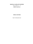
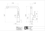
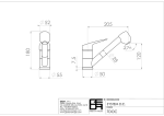
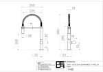
TV RADIO SAT SOCKET USER'S MANUAL 84 9 4 3 2 1 94 5 4 37.3 6 1) Cover 2) Transparent part 3) Frame 4) Screw of the cover 5) Base 6) Screw of the claw 7 8 7) Tightening screw 8) Cable fixing plate 9) Screw of the cable fixing plate Coaxial cable EXAMPLE WIRING DIAGRAMS : Example 1 : GEDA 3913 (TV/SAT/RAD) 5-862 MHz Cable TV or Central Antenna Input 950-2400 MHz Digital box distribution converted on single cable Flat Entranc TV Distributio Board in Block Input Splitter GEDA 3913 GEDA 3913 GEDA 3913 GEDA 3913 GEDA 3913 GEDA 3913 GEDA 3913 GEDA 3913 GEDA 3913 EDA3902F EDA3902FEDA3902F Example -3 : EDA 3902F (TV/SAT/RAD) 5-862 MHz Cable TV or Central Antenna Input EDA3902F Flat Entranc TV Distributio Board in Building Input Splitter EDA3902F EDA3902F LNB1 Example 2 : EDA 3902F (TV/SAT/RAD) If there will be more than one socket in a flat at multiswitch applications, a star-shaped distribution should be provided by installing a splitter at the flat entrance. UHF VHF LNB2 MULTI SWITCH Flat EDA3902F EDA3902F Entrance EDA3902F TV Distribution Board in building EDA3902F EDA3902F EDA3902F A throughpass satellite socket should never be used with multiswtich applications. Only one satellite receiver can be operated on the same way simultaneously. Specifications: CE Approved Convenient for shared antenna and SAT systems. F coket output for satellite connection. Screening up to 470 MHz ³ 75 dB ; up to 470-862 MHz ³ 65 dB; up to 950- 2400 MHz ³ 55 dB Convenient for thin coaxial cables and other coaxial cables with max. 5.5 mm exterior isolation. In accordance with IEC 169-2, EN50083-1/A1, EN50083-2/A1. Wiring Diagram: Open the cable fixing plate (8) by loosening the screw on it with a suitable screwdriver. Pay attention to leave minimum 15 cm extra cable to hold the tips of the coaxial cable from the way, incoming and outgoing in the wall case. After leaving 15 cm piece in the case, peel off the outer isolation sheath at the tips and place the conductor in the middle to its socket in the base plate and tightening screw it tightly (7). (Pay attention that the screening featured external way on the cable (Passive Way) is under the cover and not touching to the cover.) Then, place the baseplate (5) in to the wall case and fix it by tightening the pinching screws (6). Primarily, remove the cover screw on the baseplate to install the upper set (4), then mount the transparent components (2) onto the frame. Mount the upper cover on the frame as seen in the figure and after placing it so as to match the screw holes on the upper cover and the plate, fix them with the cover screw removed from the baseplate by using an appropriate screwdriver. RF f/MHz 87.5 -108 Throughpass Attenuation 1,5 Output Attenuation 13 TV-TV Decoupling RF-TV Decoupling RF-RF Decoupling SAT-SAT Decoupling 47-68 1,5 13 46 TV 174 -470 1,5 14 40 470 -862 2,0 14 36 48 SAT 950-2400 2,5 14 44 32 EDA 3902F Terminated TV Radio SAT Socket RF f/MHz 87.5 -108 Subscription Loss 2 47-68 1,5 TV 174 -470 1,5 470 -862 1,5 SAT 950-2400 2,0 Warning: For distribution, use an terminated socket at the end of the column or install a 75 Off resistance to the sockets.