1
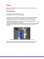
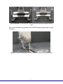
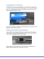
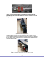
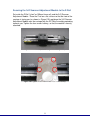
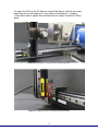
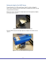
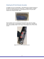
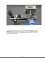
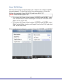
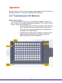
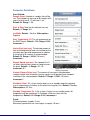
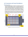
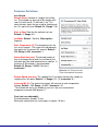
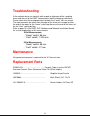
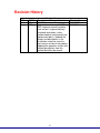
SVP-3DS-XZ
DART 3+D Scanner X-Z Transmission
User Manual
Revision 2
Document # 7.5.057
IonSense Inc.
999 Broadway
Suite 404
Saugus, MA 01906
2
Copyright © 2005-2015 by
IonSense Inc.
All rights reserved.
The information in this document has been carefully checked and is believed to
be reliable. However, no responsibility is assumed for inaccuracies. Statements
in the document not intended to create any warranty, expressed or implied.
Specification and performance characteristics of the hardware and software
described in the manual may be changed at any time without notice. IonSense
Inc. reserves the right to make changes in any product herein in order to improve
reliability, design, or function. IonSense does not assume any liability arising out
of application or use of any product or circuit described nor does it cover any
license under its patent rights or the rights of others.
The apparatus and application of the apparatus described in this document is
protected by US Patent Number 6,949,741 and used under license; additional
patents pending.
All trademarks are properties of their respective owners.
3
Table of Contents
Scope of Delivery
Standard System Components
Configuration Dependent Components
4
4
4
Functional Description
5
Safety
6
Installation
Lowering the DART-SVP Baseplate
Assembling the X-Z Transmission
Attaching the XZ Scanner Vertical Rail Mount
Securing the 3+D Scanner Adjustment Module to the Z-Rail
Raising the Height of the DART-SVP
Attaching the Limit Extender
Linear Rail Settings
6
8
8
10
13
14
16
Operation
X-Z Transmission 96 Method
X-Z Transmission 96 Temp Profile Method
17
19
Troubleshooting
21
Maintenance
21
Replacement Parts
21
Revision History
22
4
Scope of Delivery
This chapter lists the components of the X-Z Transmission.
Figure 1: Scope of Delivery
Standard System Components
1. JVL-2069-07-A
2. JVL-2064-A-TOP
3. JVL-2066-A
4. HW10084
5. SHSC_SS188_M3_5mm
6. SHSC_SS188_M3_10mm
7. HW10092
8. HW10093
9. JVLC-1011-A
10. JVL-2069-15-A
11. JVL-2069-11
12. N/A
13. Z3992-00
14. JG10019
Screen Holder Assembly, 3+D Scan XZ
XZ Plate Assembly, 3+D Scan XZ
3+D Scanner Adjustment Module
Mesh Sheet, 3+D, 74x74
Bag of M3x5 Screws Qty: 8
Bag of M3x10 Screws Qty: 16
Hex Socket Screw, XZ Assembly
Spacers, XZ Assembly
X-Z Scanner Source Standoff Assembly
XZ Limit Extender Assembly
XZ Scanner Vertical Rail Mount
Linear Rail (see below for details)
Cable, V2.0 Linear Rail Driver (not pictured.
installed inside controller)
Graphite Vespel Ferrule (not pictured)
Configuration Dependent Components
1. SI-90XX-XX
Ceramic Tubes (see the VAPUR Interface
Ceramic Tubes Reference Sheet 7.5.038 for
lengths)
2. HW10046/47
Left/Right Handed Rail motorized 100mm
Movement
NOTE: Left or right hand orientation is dependent on the Mass Spectrometer.
5
Functional Description
Figure 2: X-Z Transmission
The 3+D X-Z Transmission enables the analysis of up to 96 liquid or powder
samples on a 96-well plate mesh screen.
Definitions:
X Rail: The X Rail is the 300 mm rail that comes with the DART-SVP.
Z Rail: The Z Rail is the 100 mm rail that comes with the 3+D X-Z Transmission.
Rail Carriage: The Rail Carriage is
the part of the linear rail that moves
and has threaded holes for modules
to attach.
Figure 3: Rail with Rail Carriage highlighted
6
Safety
Refer to the SVP Hardware and Network manual for safety warnings regarding
operating the DART.
Installation
Lowering the DART-SVP Baseplate
Accommodating the X-Z Transmission Module
The baseplate for the DART-SVP ion source must be lowered using the provided
spacers in order to accommodate sampling across the entire Screen Holder
Assembly (96 samples total). These steps outline how to install the spacers.
NOTE: If the spacers are not used, none of the X-Z Transmission DART
methods in the software will run properly.
Unscrew the DART-SVP source from the baseplate to lighten the weight on the
baseplate.
Figure 4: The DART-SVP source (left) detached from the baseplate (right)
Place the long 5 mm hex head bolts through the holes on the bottom of the base
and slide the standoffs over them. See figures 5A and 5B on the next page.
7
Figure 5A and 5B: The baseplate with screws inserted (left) and with the standoffs installed
(right)
Secure the baseplate to the bottom of the VAPUR flange by tightening the long 5
mm bolts.
Figure 6: The DART-SVP baseplate attached to an interface flange, with standoffs installed
8
Assembling the X-Z Transmission
The DART-SVP ion source pictured below has an X-Rail Cradle. Simply slide
the linear rail directly into the cradle on the baseplate. The rail will click into place
when it is correctly positioned. Lock the rail into place using the 1.5 mm Allen
wrench to tighten the two set screws.
Figure 7: DART-SVP Source with X-Rail Cradle built into the source baseplate
Reference the Hardware and Network Installation Manual to determine the exact
placement of the X-Rail in the cradle.
Attaching the XZ Scanner Vertical Rail Mount
Place the XZ Scanner Vertical Rail Mount on the front of the X-Rail carriage as
pictured below. Using four M3x5 screws and the 2.5 mm Allen wrench loosely
secure the mounting block onto the X-Rail carriage.
Figure 8A: X-rail carriage without mounting block attached
Proper orientation of the XZ Scanner Vertical Rail Mount with dowel pin on
bottom and holes lined up with the front of the rail stage.
9
Figure 8B: Partially tighten the four 2.5 mm Allen head screws
The XZ Scanner Vertical Rail Mount has threaded holes on both sides to be
compatible with both left and right handed rails. Install the set screws in the side
facing the motor.
Figure 9: Set screws facing the motor.
Completely tighten the two 1.5 mm set screws on the side of the XZ Scanner
Vertical Rail Mount to square the alignment of the block and then finish tightening
the four 2.5 mm screws on the front of the XZ Scanner Vertical Rail Mount to fully
secure the mounting block.
Figure 10: Completely tighten the two 1.5 mm Allen head set screws
10
Securing the 3+D Scanner Adjustment Module to the Z-Rail
Set aside the Z-Rail (“short” or 100mm linear rail) and the 3+D Scanner
Adjustment Module. Place the Z-rail on a flat surface so that the front of the
carriage is facing you (as shown in Figure 11A) and place the 3+D Scanner
Adjustment Module over the carriage with the XZ Plate Assembly protruding
towards you. Tighten the four screws halfway, so that the module is loosely
attached.
Figure 11A: The Z-rail (shown in a “right hand” configuration)
Figure 11B. Tighten the four 2.5 mm Allen head screws halfway.
11
Once the module is secured to the block, take a 1.5mm Allen wrench and tighten
the two set screws on the back of the module. This will fix the position of the
module and help keep the sample plate level.
Figure 12: Using the 1.5 mm Allen wrench, tighten the two set screws on the back of the module
Once the set screws are tight, fully tighten the 2.5 mm Allen head screws.
Figure 13: The 3+D Scanner Adjustment Module successfully attached to the Z-Rail
12
To attach the Z-Rail to the XZ Scanner Vertical Rail Mount, slide the non-motor
end of the rail into the cradle until it rests against the dowel pin. Using the
1.5mm Allen wrench, tighten the two Allen head set screws to lock the Z-Rail in
place.
Figure 14: Installing the Z-Rail into the X-Z Mounting Block
Figure 15: Tighten the two 1.5 mm Allen head set screws
13
Raising the Height of the DART Source
To accommodate the full 96 sample Screen Holder Assembly and keep the
DART source’s alignment with the VAPUR tube, the height of the DART must be
increased relative to the base.
Remove the source, then place the height adjustor on the baseplate and tighten
the thumb screw to secure it.
Figure 16: The height adjustor attached to the baseplate.
Place the DART source on the height adjustor and tighten the thumb screw to
secure it.
Figure 17: The DART source attached to the height adjuster.
14
Attaching the XZ Limit Extender Assembly
Installation of an extra interlock piece is required to prevent accidental damage to
the DART unit while using the X-Z transmission. The piece contains a magnet
that limits the travel distance of the X-rail and prevents the X-Z transmission
module from striking the DART source.
Figure 18: The limit extender
Place the piece on the rail so that the limit extender hangs over the carriage
away from the motor, as pictured below. Secure it in place to the stage with the
two screws provided (circled in red in Figure 19) and tighten with a 2.5 mm Allen
wrench.
Figure 19: Top view of the safety interlock piece
15
Figure 20: The X-Z Transmission Module attached to the DART-SVP source
Insert the longer ceramic tube into the VAPUR inlet, taking care to leave a 2 mm
gap between the end of the ceramic tube and the API inlet. Refer to the specific
VAPUR Flange Manual for the mass spectrometer that the DART-SVP is being
installed on for more details.
16
Linear Rail Settings
The linear rails must be set to the proper side in order for the software methods
to execute properly. To check the current linear rail parameters, click on the
Settings tab; open both Linear Rail #1 (X) and Linear Rail #2 (Z).
NOTE: Linear Rail #2 is your Z rail
•
•
For systems with linear rail part numbers HW10029 and HW10047 select
“Left” for both Motor Location and Sample From for the X-Rail and select
“Right” for the short Z-Rail.
For systems with linear rail part numbers HW10039 and HW10046 select
“Right” for both Motor Location and Sample From for the X-Rail and select
“Left” for the short Z-Rail.
Below are the correct settings for a system with part #s HW10029 and HW10047.
Figure 21: Linear Rail Settings
17
Operation
The 3+D Scanner X-Z Transmission supports two methods: the XZ Transmission
96 Method and the XZ Transmission 96 Temp Profile Method.
X-Z Transmission 96 Method
Method Description:
This method enables the analysis of up to 96 liquid or powder samples on a
mesh screen at a user defined speed and temperature. The user can start the
analysis from any of the 8 rows (A-H).
For each sample the X-Z transmission goes to the front edge
of the sample, the controller sends out the contact closure
here, and scans at the user defined linear rail speed across
the length of the sample (9mm).
In between each sample the rail will pause, wait for the user
defined contact closure delay time and then repeat the
above step until each row is completed.
Figure 22: XZ Transmission 96 Method Scan path
18
Parameter Definitions:
User Defined:
Sample Count: Number of samples that will be
run. The method can have up to 96 samples with
row A, 84 with row B, 72 with row C, etc.
Default=96, Range 1- 96
Start at Row: Row that the method starts on.
Default= A, Range A-H
Ion Mode: Default = Positive, Other option=
Negative
Start Temperature (C): The set temperature for
the DART heater. Default = 350; Range=0-500,
increment= 1
Heater Wait time (sec): The desired amount of
time at the beginning of each run to allow for the
ionization gas flow and temperature to stabilize.
A minimum of 30 seconds is recommended.
Default=30, Range=1-65563 (18 hours),
Increment=1
Sample Speed (mm/sec): The speed of the Xrail when moving from sample to sample across
the plate. Default= .5, Range= 0.2 -10,
increment= 0.1
Figure 23: X-Z Transmission 96
Method Parameters
Contact Closure Delay (sec): The amount of time spent sitting between
samples to give time for contact closure signals and to provide some temporal
resolution in the chromatogram. Default=5, Range=1-65563 (18 hours),
Increment=1
Shutdown State: The system can be kept in run or standby mode for repeated
use or automatically shut down at the end of the analytical run. Default= Standby,
Other options: Off, Run
Standby Temperature (C): If the system is kept in run or standby mode, this
temperature will be maintained. It should be a little less than the start
temperature. Default=345; Range=0-500, Increment=1
Fixed:
Distance between samples: 9 mm
Movement speed when not scanning on a sample: 10 mm/s
19
X-Z Transmission 96 Temp Profile Method
Method Description:
This method is used to optimize the DART heater temperature by analyzing a
maximum of 64 liquid or powder samples at 4 user defined temperatures (2
samples per temperature per row.) (3 of the sample spots per row are used
as blanks to heat to the next temperature.) The method starts 4.5mm from the
center of sample 1 (Method Position 1), triggers the contact closure and
scans across it and the next sample at a user defined speed and temperature.
It then travels to the 3rd sample to heat to the next temperature. It continues
like this until it scans across all samples in the row. It then travels around the
plate to the next row, cools down to the starting temperature and repeats until
all samples have been analyzed. The user can start the analysis from any of
the 8 rows (A-H). Contact closure activates only at the beginning of each
row. The spots where heating occurs are blank spots. There is also a blank
spot on sample 12.
Figure 24: XZ Transmission 96 Temp Profile Scan Path
20
Parameter Definitions:
User Defined:
Sample Count: Number of samples that will be
run. The method can have up to 96 samples with
row A, 84 with row B, 72 with row C, etc. This
count includes spots that are used for heating and
the 12th spot at the end. Default=96 , Range 1- 96
Start at Row: Row that the method starts on.
Default= A, Range A-H
Ion Mode: Default = Positive, Other option=
Negative
Start Temperature (C): The temperature for the
first set of samples. The heater will subsequently
heat up by the “Increment By” amount. Default =
350; Range=0-500, increment= 1
Heater Wait time (sec): The desired amount of
time at the beginning of each run to allow for the
ionization gas flow and temperature to stabilize. A
minimum of 30 seconds is recommended.
Default=30, Range=1-65563 (18 hours),
Increment=1
Figure 25: X-Z Transmission 96:
Temp Profile Method Parameters
Sample Speed (mm/sec): The speed of the X-rail when moving from sample to
sample across the plate. Default= .5, Range= 0.2 -10, increment= 0.1
Increment By (C): The amount the heater will increase at each temperature
change. Default = 100, Range = 0-500*, increment = 0.1
*The method will end in the middle of your run if the next incremented
temperature exceeds 500 degrees C.
Fixed (not user adjustable):
Distance between samples: 9 mm
Movement speed when not scanning on a sample: 10 mm/s
21
Troubleshooting
If the methods do no run correctly with respect to alignment of the sampling
areas and the exit of the DART source please read the following statements.
Please check that the carriage positions for both the X and Z rails are correct.
The measurements are taken from the edge of the linear rail carriage to either
the end of the motor for the “Home” switch position or to the end of the linear rail
for the “Limit” switch position.
Refer to page 15 in the DART-SVP Hardware and Network Installation Manual
for a visual explanation of this measurement.
X-Rail Measurements
- "Home" switch: 56 mm
- "Limit" switch: 134.5 mm
Z-Rail Measurements
- "Home" switch: 56 mm
- "Limit" switch: 27 mm
Maintenance
No special maintenance is required for the X-Z transmission.
Replacement Parts
SI-90XX-XX………………………………..Ceramic Tubes (see the VAPUR
Interface Ceramic Tubes Reference Sheet 7.5.038 for lengths)
JG10019…………………………………….
Graphite Vespel Ferrule
HW10084…………………………………..
Mesh Sheet, 3+D, 74x74
JVL-2069-07-A……………………………..
Screen Holder, 3+D Scan XZ
22
Revision History
REV
1
2
DCR #
43
200
Revision History
Description of Change
Initial Release
Updated format to match DARTSVP hardware manual including
new sections (scope of delivery,
functional description, safety,
troubleshooting, maintenance and
replacement parts). Updated the
photos and descriptions in the
installation section to show the
most recent version of the product.
Updated the operation section with
method descriptions from the
method definition documents.
23
Effective Date
11/11/2013
4/09/2015