1
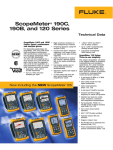
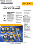
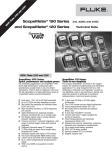
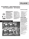
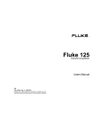
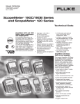
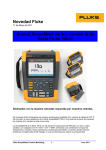
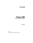
ScopeMeter 120 and 190 Series ® incl. 225C and 215C ScopeMeter 215C, 225C and 190C Series: Speed, performance and analysis power QU AL RT IF ED 90 CE 01 EM ST ANAGEMENT S YM Y IT TO MEET IS O For demanding applications, the ScopeMeter 215C, 225C and 190C Series high-performance oscilloscopes offer specifications usually found on top-end bench instruments. With up to 200 MHz bandwidth, 2.5 GS/s real time sampling and a deep memory of 27,500 points per input, they’re ideal for engineers who need the full capabilities of a high-performance scope in a handheld, battery powered instrument. • Dual input - 200, 100 or 60 MHz bandwidth • Up to 2.5 GS/s real time sampling per input • Bus Health Test capability for industrial buses (225C and 215C) • High waveform resolution of 3000 datapoints per channel • Frequency Spectrum using FFT analysis • Connect-and-View™ automatic triggering, a full range of manual trigger modes plus external triggering • Digital Persistence for analyzing complex, dynamic signals like on an analog oscilloscope • Fast display update rate for seeing dynamic behavior instantaneously Automatic capture and replay of • 100 screens • 27,500 points and more per input record length using ScopeRecord™ mode Technical Data • 1,000 V CAT II and 600 V CAT III safety certified • Up to 1,000 V independently floating isolated inputs • 5000 count DMM and paperless recorder built-in • Four hours rechargeable NiMH battery pack ScopeMeter 120 Series: Three-in-one simplicity The compact ScopeMeter 120 Series is the rugged solution for industrial troubleshooting and installation applications. It’s a truly integrated test tool, with oscilloscope, multimeter and “paperless” recorder in one affordable, easy-to-use instrument. Find fast answers to problems in machinery, instrumentation, control and power systems. • A dual input 40 MHz or 20 MHz digital oscilloscope • Two 5,000 counts true-rms digital multimeters • Cursor measurements (Fluke 124, 125) • A dual input TrendPlot recorder • Connect-and-View trigger simplicity for hands-off operation • Shielded test leads for oscilloscope, resistance, continuity and capacitance measurements • Full bandwidth, VPS40 10:1 40 MHz probe included standard with Fluke 124, 125 • Up to seven hours battery operation • 600 V CAT III safety certified • Optically isolated RS-232 interface • Rugged, compact case • Bus Health test for industrial bus systems (Fluke 125) • Power measurements and harmonics measurement (Fluke 125) Technical specifications 215C, 225C and 190C Series Oscilloscope mode Horizontal Vertical deflection Pulse width triggering: Pulse width qualified by time. Allows for triggering <t, >t, =t, ≠t, where t is selectable in minimal steps of 0.01 div. or 50 nsec. Time delay: One full screen of pre-trigger view or up to 100 screens (= 1200 divisions) of post-trigger delay Dual slope triggering: Triggers on both rising and falling edges alike N-cycle triggering: Triggers on N-th occurrence of a trigger event; N to be set in the range 2 to 99 Bandwidth Rise time Fluke 225C Fluke 199C 200 MHz 1.7 ns Fluke 215C Fluke 196C 100 MHz 3.5 ns Fluke 192C 60 MHz 5.8 ns Bandwidth limiter: User selectable: 10 kHz, 20 MHz or off Number of inputs: Two plus external trigger. All inputs references isolated from each other and ground. Input coupling: AC or dc, with ground level indicator Input sensitivity: 2 mV/div to 100 V/div Normal/invert: On both input channels; switched separately Variable attenuator: Variable gain on input channel A Input voltage: 1000 V CAT II, 600 V CAT III rated—see “general specifications” for further details Vertical resolution: 8 bit Accuracy: ± (1.5 % of reading + 0.04 x range/div) Input impedance: 1 MW ± 1 % // 15 pF ± 2 pF Maximum real-time sample rate Number of digitizers Time base range Fluke 225C Fluke 199C 2.5 GS/s Fluke 215C Fluke 196C 1 GS/s Fluke 192C 2 2 2 500 MS/s Automatic capture of 100 screens The instrument ALWAYS memorizes the last 100 screens (no user setup required). When an anomaly occurs on screen, the REPLAY button can be pressed to review the full screen sequence over and over. Instrument can be set up for triggering on glitches or intermittent anomalies and will operate in “baby-sit” mode capturing 100 events. Replay: Manual or continuous replay. Displays the captured 100 screens as a “live” animation, or under manual control. Each screen has date and time-stamp. Replay storage: Up to 2 sets of 100 screens each can be saved for later recall and analysis FFT – Frequency spectrum analysis Maximum record length: 3000 points per input in Scope mode; 27,500 points per input in ScopeRecord™ roll mode (5 ms/div to 2 min/div) Accuracy: ± (0.01 % of reading + 1 pixel) Glitch capture: 50 nsec (5 μsec/div to 1 min/div) Shows frequency content of oscilloscope waveform using Fast Fourier Transform Window: Automatic, Hamming, Hanning or None Automatic window: Digitally re-samples acquired waveform to get optimum frequency resolution in FFT resultant Vertical scale: Linear/logarithmic, in volts Frequency axis: Logarithmic; frequency range automatically set as function of timebase range of oscilloscope Display and acquisition Waveform compare and pass/fail testing Display: 144 mm full-color LCD, with backlight Display modes: Input A, input B, dual, average, Replay Visible screen width: 12 divisions Waveform mathematics: A + B, A - B, A * B, all with user selectable scaling of resultant; A versus B (X - Y mode); Frequency spectrum using FFT analysis Acquisition modes: Normal, auto, single shot, ScopeRecord™ roll, glitch capture, waveform compare, waveform compare with automatic “Pass / Fail testing”, Bus Health test mode (225C and 215C only), Eyepattern Display of single ended or differential bus signal (Fluke 225C and 215C only). Waveform compare: Provides storage and display of a reference waveform for visual comparison with newly acquired waveforms. Reference is derived from an acquired waveform and can be modified in the ScopeMeter or externally using FlukeView® Software. Pass/Fail Testing: In waveform compare mode, the Color Scopemeter can be set up to store only matching (“Pass”) or only non-matching (“Fail”) acquired waveforms in the replay memory bank for further analysis. 5 ns/div to 5 s/div 10 ns/div to 5 s/div Trigger and delay Source: Input A, input B, external trigger input. All input references isolated from each other and from ground Modes: Automatic Connect-and-View,™ free run, single shot, edge, delay, video, video line, selectable pulsewidth, dual slope, N-cycle Connect-and-View™: Advanced automatic triggering that recognizes signal patterns, automatically sets up and continuously adjusts triggering, time base and amplitude. Automatically displays stable waveforms of complex and dynamic signals like motor drive and control signals. Can be switched off if desired. Video triggering: NTSC, PAL, PAL+, SECAM. Includes field 1, field 2 and line select 2 Fluke Corporation Automatic scope measurements V dc, V ac rms, V ac+dc, Vpeak max, Vpeak min, Vpeak to peak, A ac, A dc, A ac+dc, frequency (Hz), risetime, falltime, power factor, Watts, VA, VA reactive, phase, pulse width (pos/neg), dutycycle (pos/neg), temperature °C, temperature °F, dBV, dBm into 50 Ω and 600 Ω Vpwm ac, Vpwm ac+dc for measurement on pulse width modulated motordrives and frequency inverters Cursor measurements Source: Input A, input B or the mathematical result trace (excluding A vs B curve) Dual horizontal lines: Voltage at cursor 1 and 2, voltage between cursors Dual vertical lines: Time between cursors, 1/T between cursors (in Hz), voltage between markers, risetime with markers, falltime with markers; Vrms between cursors, Watts between cursors Single vertical line: Min-Max and average voltage at cursor position; frequency and rms-value of individual frequency component in FFT result ScopeMeter 215C, 225C and 190C Series, 120 Series Zoom Recorded timespan: Up to 22 days with a resolution of 1 minute Recording mode: Continuous roll for the duration of the full recordable timespan Bus health test mode Measurement speed: 5 measurements per second (Fluke 225C and 215C only) Horizontal scale: Time from start, time of day Zoom: Up to 64x zoom Bus Health automatically analyzes the electrical signals Memory: Up to 2 TrendPlot recordings can be saved on the industrial bus system to measure individual for later recall and analysis parameters and to give waveform information. Automatically compares the measurement results to Cursor measurements—all recorder modes preset values and present ‘good’, ‘weak’ or ’false’ Source: Input A, B or DMM input indicator with each parameter. Dual vertical lines: Min-Max or Average Bus types and reference standards used: voltage. Time between cursors AS-i (EN50295, 166 kb/s); Single vertical line: Min-Max or Average CAN-bus (ISO-11898, up to 1 Mb/s); voltage. Absolute date and time or time from start Modbus (EIA-232 up to 115 kb/s and EIA-485 up to 10 Mb/s); Meter mode Foundation Fieldbus H1 (61158 type 1, 31.25 kb/s); Profibus DP (EIA-485 up to 10 Mb/s) and PA (61158 Via 4 mm banana inputs. Fully isolated from scope type 1, 31.25 kb/s); inputs and scope ground. The specified accuracy is Ethernet [10Base2 (coaxial) and 10BaseT (UTP)], valid over the temperature range 18 °C to 28 °C 10 Mb/s; (65 °F to 82 °F). Add 10 % of specified accuracy for Ethernet 100BaseT (100 Mb/s); each degree C below 18 °C or above 28 °C. RS-232 (EIA-232, up to 115 kb/s); Maximum resolution: 5,000 counts RS-485 (EIA-485, up to 10 Mb/s). Voltmeter ranges: 500 mV, 5 V, 50 V, 500 V, 1,000 V Measured parameters (where applicable): Accuracy: Bias voltage level, signal amplitude, pulse width or V dc ± (0.5 % + 5 counts) baud rate, risetime, fall time, jitter, signal distortion, V ac true rms noise HF, noise LF, in-band noise. 15 Hz to 60 Hz: ± (1 % + 10 counts) 60 Hz to 1 kHz: ± (2.5 % + 15 counts) Recorder mode V ac+dc true rms dc to 60 Hz: ± (1 % + 10 counts) ScopeRecord—roll mode 60 Hz to 1 kHz: ± (2.5 % + 15 counts) Dual input waveform storage mode Ohms: Source and display: Input A, input B, dual Ranges: 500 Ω, 5 kΩ, 50 kΩ, 500 kΩ, 5 MΩ, 30 MΩ Memory depth: 27,500 points per input. Each point Accuracy: ± (0.6 % + 5 counts) consists of Min-Max pair Min-Max values: Min-Max values are measured at Other meter functions high sample rates ensuring capture and display of Continuity: Beeper on < 50 Ω (± 30 Ω) glitches Diode test: Up to 2.8 V Time base range 5 ms/div to 1 min/div 2 min/div Amps: A dc, A ac, A ac+dc using an optional current clamp or shunt. Scaling factors: 0.1 mV/A ... 100 V/A Recorded timespan 6 sec to 24 hr 48 hr Temperature (°C, °F): With optional accessories. Scale Glitch capture 50 ns 250 ns factors 1 mV/°C or 1 mV/°F Sample rate 20 MS/s 4 MS/s Input impedance: 1 MΩ ± 1 %/10 pF ± 2 pF Resolution 200 µsec to 2 sec 4.8 sec Advanced meter functions: Auto/manual ranging, relative measurements (zero reference), TrendPlot Recording modes: Single sweep, continuous roll, recording Start-on-Trigger (through external), Stop-on-Trigger (through external) General specifications Stop-on-Trigger (through external): ScopeRecord mode can be stopped by an individual trigger event, or Input voltage ratings by an interruption of a repetitive trigger signal Horizontal scale: Time from start, time of day Maximum probe voltage: CAT II 1,000 V, CAT III Zoom: Up to 100x 600 V (Maximum voltage between 10:1 probe tip Memory: Up to 2 dual input ScopeRecord waveforms (VPS210) and reference lead) can be saved for later recall and analysis Floating voltage: CAT II 1,000V, CAT III 600 V (Maximum voltage between earth ground and any TrendPlot™ recording terminal (signal input or shielding)) Single or dual input electronic paperless chart Independently isolated inputs: CAT II 1,000 V, recorder. Plots, displays and stores meter and scope CAT III 600 V (Maximum voltage between any terminal measurements. of one input or probe (VPS210) and any other terminal Source and display: Input A, input B or DMM input of another input or probe (VPS210)) Memory depth: 18,000 points recording. Per record Maximum voltage on BNC input directly point a minimum, a maximum and an average value, (input A or B): CAT III 300 V plus a date and timestamp are recorded. Maximum voltage on meter input: CAT II 1,000 V, Ranges: 5 s/div to 30 min/div in normal view mode; CAT III 600 V 5 min/div to 48 hr/div in view all mode, giving overview of total record Up to 16x horizontal zoom ScopeMeter 215C, 225C and 190C Series, 120 Series Fluke Corporation 3 Memory save and recall Input voltage ratings Scope memories: 15 memory locations that each can contain two waveforms plus corresponding setup. With each storage action, a user specified name (20 ASCII characters long) can be assigned to the stored data, for easier reference. Recorder memories: 2 memory locations that each can contain 100 captured dual input scope screens, or a dual input ScopeRecord (27,500 Min-Max pairs per input), or a dual input Trendplot (18,000 min-max pairs + average values) Maximum probe voltage: CAT II 1000 V/ CAT III 600 V (Maximum voltage between 10:1 probe tip [VPS200] and reference lead) Floating voltage: CAT II 1000 V/ CAT III 600 V (Maximum voltage between earth ground and any terminal [signal input or shielding]) Independently isolated inputs: CAT II 1000 V/ CAT III 600 V (Maximum voltage between any terminal of one input or probe [VPS200] and any other terminal of another input or probe [VPS200]) Maximum voltage on BNC input directly (input A or B): CAT III 300 V Maximum voltage on meter input: CAT II 1,000 V/ CAT III 600 V Real-time clock Time and date stamp for ScopeRecord, 100 captured screens and TrendPlots Mechanical data Size: 256 mm x 169 mm x 64 mm (10.1 in x 6.6 in x 2.5 in) Weight: 2 kg (4.4 lbs) Case Design: Rugged, shock proof with integrated protective holster Drip and dust proof: IP51 according to IEC529 Shock and vibration: Shock 30g, Vibration (sinusoidal) 3g according to MIL-PRF-28800F Class 2 Display: Bright full-color LCD with backlight Brightness: 80 Cd/m2 typ. using power adapter Display size: 115.2 mm x 86.4 mm (4.54 in x 3.4 in); 144 mm (5.67 in) diagonal Resolution: 320 x 240 pixels Contrast and brightness: User adjustable, temperature compensated Brightness: 80 cd/m2 typ. using power adapter Power Line power: Country-specific line voltage adapter/battery charger included Battery power: Rechargeable NiMH (installed) Battery operating time: 4 hours Battery charging time: 4 hours Battery power saving functions: Auto power down with adjustable power down time. On-screen battery status indicator. Safety Compliance: EN61010-1-2001, Pollution degree 2; UL61010B, with approval; CAN/CSA C22.2, No. 61010-1-04, with approval; ANSI/ISA-82.02.01 Environmental Operating temperature: 0 °C to +50 °C Storage temperature: -20 °C to +60 °C Humidity: 10 °C to 30 °C: 95 % RH non condensing 30 °C to 40 °C: 75 % RH non condensing 40 °C to 50 °C: 45 % RH non condensing Maximum operating altitude: 3,000 m (10,000 feet) Maximum storage altitude: 12 km (40,000 feet) Electro-Magnetic-Compatibility (EMC): EN 61326-1 for emission and immunity Optically-isolated PC/printer interface To printer: Supports HP Laserjet,® DeskJet, Epson FX/LQ, Seiko DPU-414 and Postscript printers via optional PAC 91 To PC: Transfer instrument settings, screen images and waveform data, compatible with FlukeView® software for Windows® via optional OC4USB or PM9080. Warranty Three-years, parts and labor on mainframe instrument One-year on accessories Accessories Standard accessories Fluke 215C, 225C and 190C Series Rechargeable battery pack (installed) BP190 Line voltage adapter/ battery charger BC190 Voltage probes and accessories 10:1 voltage probe (VPS200, 1 red + 1 grey) including hook clip, ground lead with mini alligator clip, ground spring for probe tip Multimeter test leads TL75 Hard Point test lead set (1 red, 1 black) User manual Multi-lingual CD-ROM 215C and 225C additional accessories Three breakout adapters for bus systems using RJ45, DB9, and M12 connectors. 4 Fluke Corporation ScopeMeter 215C, 225C and 190C Series, 120 Series BHT190 Technical specifications 120 Series Oscilloscope mode Cursor measurements (125, 124) Vertical deflection Sources: Input A, Input B Modes: Single or dual vertical cursor, dual horizontal cursor, risetime or falltime Measurements: Single vertical line: Average, min value, max value, time from start of recording in roll mode Dual vertical lines: ∆V at markers, time between cursors, 1/T between cursors (in Hz) Dual horizontal lines: High, low or ∆V – readout, risetime and falltime: transition time, 0 %-level, 100 %-level, with markers at 10 % and 90 % Accuracy: As oscilloscope Bandwidth and risetime Fluke 125, 124 Fluke 123 Bandwidth (risetime) • with VPS40 probes 40 MHz 20 MHz • input A and B directly • with STL120 Shielded 40 MHz 20 MHz 12.5 MHz 12.5 MHz Instrument risetime (input directly) 8.75 ns 17.5 ns Test Leads Number of inputs: two Input coupling: ac, dc with ground level indicator Input sensitivity: 5 mV to 500 V/div (with the included VPS40 (Fluke 125, 124) and STL120 shielded test leads measure up to 600 Vrms, CAT III) Input voltage: 600 V CAT III. See “general specifications” for more detailed information. Vertical resolution: 8 bit Accuracy: ± (1 % of reading + 0.05 x range/div) Input impedance: 1 MΩ ± 1 % // 225 pF with STL120 shielded test leads; 1 MΩ ± 1 % // 20 pF ± 3 pF with BB120; 5 MΩ ± 1 % // 15.5 pF with VPS40, 10:1 voltage probe Horizontal Max. sample rate (both channels simultaneously): Fluke 125, 124: 2.5 GS/s for repetitive signals; 25 MS/s for single shot Fluke 123: 1.25 GS/s for repetitive signals; 25 MS/s for single shot Number of digitizers: two Time base range: 10 ns/div to 1 min/div (Fluke 125, 124) Maximum record length: 512 Min/Max points per input Accuracy: ± (0.1 % of reading + 1 pixel) Glitch detect: 40 ns Display and acquisition Display modes: Input A, input A and B, envelope, smooth Acquisition modes: Normal (including glitch capture), single shot, roll Trigger and delay Source: Input A, input B, external via optional ITP120 Modes: Automatic Connect-and-View, Free Run, Edge, Single Shot, Video, Video Line Connect-and-View: Advanced automatic triggering that recognizes signal patterns and automatically sets up and continuously adjusts triggering, time base and amplitude. Automatically displays stable pictures of complex and dynamic signals like motor drive and control signals Video triggering: NTSC, PAL, PAL+, SECAM. Includes line select Time delay: Up to 10 divisions pre-trigger view Measurements Vdc, Vac, Vac+dc, Vpeak max, Vpeak min, Vpeak to peak, frequency (Hz), positive pulse width, negative pulse width, positive duty cycle, negative duty cycle, Amp ac, Amp dc, Amp ac+dc, Phase, Temperature °C, Temperature °F, dBV, dBm into 50 Ω and 600 Ω. (Amps, °C or °F with optional probes) Bus health tester (Fluke 125 only) Bus health automatically analyzes the electrical signals on the network to give waveform data and measure individual parameters. Automatic comparison of the measurement results to the standards results in “good” or “false” indicators to be displayed per parameter. Bus types and reference standards used: AS-i (EN50295, 166 kb/s)®; CAN-bus (ISO-11898, up to 1 Mb/s); Interbus S (EIA-485, up to 10 Mb/s)®; ControlNet (61158 type 2, 2.5 Mb/s)®; Modbus (EIA-232, up to 115 kb/s and EIA-485, up to 10 Mb/s)®; Foundation Fieldbus H1 (61158 type 1, 31.25 kb/s) and H2 (61158 type 1, up to 10 Mb/s); Profibus DP (EIA-485, up to 10 Mb/s) and PA (61158 type 1, 31.25 kb/s); Ethernet [10Base2 (coaxial) and 10BaseT (UTP)], 10 Mb/s; RS-232 (EIA-232, up to 115 kb/s); RS-485 (EIA-485, up to 10 Mb/s); or user defined system Measured parameters: Baud rate, risetime, falltime, high level, low level, distortion, amplitude and jitter, with comparison to system’s standard values Power measurements (Fluke 125 only) Measure types: Watt, VA, VAR, Power Factor (PF) Power configuration: Single phase or balanced 3-phase (delta-configuration) mains supply Voltage measurement: Channel A, using STL120, voltage probe or direct input Current measurement: Channel B, using i400s current clamp (included) or other compatible clamp Current clamp or shunt sensitivity: 0.1/1/10/100/1000 mV/A, 10 mV/mA and 400 mV/A Harmonics mode (Fluke 125 only) Converts waveform information into a harmonics display (using FFT processing), which shows the relative amplitudes of the 1st up to the 33rd harmonic Harmonics frequency range: DC to 33rd harmonic (fundamental ≤ 60 Hz); DC to 24th (fundamental ≤ 400 Hz) Analyzed waveform: Voltage waveform (Ch.A), current waveform (Ch.B) or power (Ch.A x Ch.B), automatically generated Display: Bargraph showing 1st up to 33rd harmonic, amplitude displayed in % relative to fundamental Timebase setting: 5 ms/div. Measurements: Relative amplitude of individual harmonic; THD in %r or %f ScopeMeter 215C, 225C and 190C Series, 120 Series Fluke Corporation 5 Dual input meter Recorder mode The specified accuracy is valid over the temperature range 18 °C to 28 °C (64 °F to 82 °F). Add 10 % of specified accuracy for each °C below 18 °C or above 28 °C (64 °F to 82 °F) Max. meter bandwidth: 40 MHz (Fluke 125, 124), 20 MHz (Fluke 123) Trendplot recording Voltage measurements Dual input electronic paperless chart recorder. Plots and displays the actual, minimum, maximum and average of any measurement. Source and display: Input A, input A and B Range: 15 s/div to 2 days per division (automatic) Recorded timespan: Up to 16 days with a resolution of 1.5 hours Recording mode: Continuous with automatic vertical scaling and horizontal time compression Measurement speed: 2.5 measurements per second maximum Horizontal scale: Time from start Measurement selection: V dc, V ac rms, V ac+dc rms, Vpeak max, Vpeak min, Vpk-pk Ranges: 500 mV, 5 V, 50 V, 500 V, 1250 V Full scale reading: 5,000 counts Accuracy V dc: ± (0.5 % + 5 counts) V ac rms: 1 Hz to 60 Hz: ± (1 % + 10 counts) 60 Hz to 1 kHz: ± (2.5 % + 15 counts) 20 kHz to 1 MHz ± (5 % + 20 counts) V ac+dc true-rms: DC to 60 Hz: ± (1 % + 10 counts) 60 Hz to 1 kHz: ± (2.5 % + 15 counts) 20 kHz to 1 MHz (5 % + 20 counts) V ac pwm: Measures the effective output voltage of pulse-width modulated motordrives and frequency inverters (Fluke 125 only) Vpeak: Max peak or Min peak: 5 % of full scale Peak-to-peak: 10 % of full scale A ac+dc true-rms, A ac, A dc: Current Clamp or shunt sensitivity: 0.1 mV/A, 1 mV/A, 10 mV/A, 100 mV/A, 400 mV/A, 1 V/A or 10 mV/mA. Bright LCD with CCFL backlight, 60 (35) cd/m2 with (without) power adapter Size: 72 mm x 72 mm (2.8 in x 2.8 in) Resolution: 240 x 240 pixels Contrast and brightness: User adjustable, temperature compensated Ohms Memory save and recall Ranges: 500 Ω, 5 kΩ, 50 kΩ, 500 kΩ, 5 MΩ, 30 MΩ (all models), 50.00 Ω (Fluke 125 only) Max. resolution: 5,000 counts Accuracy: ± (0.6 % of reading + 5 counts) Capacitance Ranges: 50 nF to 500 µF Max. resolution: 5,000 counts Accuracy: ± (2 % of reading + 10 counts) Other meter functions Frequency: Up to 70 MHz (Fluke 125, 124) or up to 40 MHz (Fluke 123) Rotational speed (RPM): Revolutions per minute, based on 1, 2 or 4 or 8 pulses per 2 revolutions (Fluke 125 only) Max. RPM reading: 50 kRPM Continuity: Beeper on < 30 Ω Diode test: Up to 2.8 V Duty cycle: 2 % to 98 %, up to 30 MHz Temperature (°C, °F): With optional accessories. Scale factors 1 mV/°C or 1 mV/°F Number of inputs: 2 Input impedance: 1 MΩ ± 1 %/10 pF ± 2 pF Advanced meter functions: Auto/manual ranging, TouchHold®, Relative measurements (zero reference), TrendPlot recording 6 Fluke Corporation General specifications Case Design: Rugged, shock proof with integrated protective holster Drip and dust proof: IP51 according to IEC529 Shock and vibration: Shock 30 g according to MIL-PRF-28800F, Class 2, par. 3.8.4.2 and 4.5.5.3.1 Shock and vibration: Vibration 3 g according to MIL-PRF-28800F, Class 2, par. 3.8.5.1 and 4.5.5.4.1 Display 20 (Fluke 125, 124) and 10 (Fluke 123) instrument screens with user set-ups and user text Real-time clock Time and date stamp TrendPlot recording Power Line power: Country-specific line voltage adapter/battery charger included Battery power: Rechargeable Ni-MH BP120MH (installed) Battery operating time: Up to 7 hours using BP120MH Battery charging time: 7 hours Battery power saving functions: Auto power down with adjustable power down time. On-screen battery power indicator Mechanical data Size: 50 mm x 115 mm x 232 mm (2 in x 4.5 in x 9.1 in) Weight: 1.2 kg (2.64 lb) Safety Compliance: EN61010-1-2001, Pollution degree 2; CAN/CSA C22.2, No. 61010-1-04, including CCSAUS-approval; ANSI/ISA-82.02.01 ScopeMeter 215C, 225C and 190C Series, 120 Series Input voltage ratings Maximum input voltage: CAT III 600 V (Maximum voltage between input and reference lead) Maximum input voltage using VPS40 Probe: CAT III 600 V, CAT II 1000 V (Maximum voltage between probe tip input and reference lead) Floating voltage: CAT III 600 V (Maximum voltage between earth ground and any terminal [signal input or reference lead]) Maximum voltage between reference leads: Instrument has common grounds connected via self recovering fault protection. For different ground potential measurements between inputs, use DP120 differential voltage probe or a Fluke 190C Series instrument. Environmental According to MIL-PRF-28800F, Class 2 Maximum operating altitude: 2,000 m (6,500 ft) 4,500 m (15,000 ft) voltages ≤ 300 V Maximum storage altitude: 12 km (40,000 ft) Electro-Magnetic-Compatibility (EMC): EN61326-1 for emissions and immunity Optically isolated PC/printer interface To printer: Supports HP Laserjet®, Deskjet®, Epson FX/LQ and postscript printers via optional PAC91 To PC: Transfer instrument settings, screen images and data, compatible with FlukeView® software for Windows® via optional OC4USB (USB) or PM9080 (RS-232) interface cable. Warranty Three-years (parts and labor) on main instrument One-year on accessories Operating temperature: 0 °C to +50 °C Storage temperature: -20 °C to +60 °C Humidity: 10 °C to 30 °C, 95% RH non condensing; 30 °C to 40 °C, 75% RH non condensing; 40 °C to 50 °C, 45% RH non condensing FlukeView® ScopeMeter® Software for Windows® FlukeView ScopeMeter software helps you get more out of your ScopeMeter: • Store instrument’s screen copies on the PC, in color (with Fluke 190C-Series only) or in black and white • Copy screen images into your reports and documentation Capture and store waveform data from your • ScopeMeter on your PC • Create and archive waveform references for automatic (Fluke 190C Series) or visual (Fluke 190B and 190C Series) comparison • Includes waveform analysis, e.g. FFT spectrum analysis Copy waveform data into your spreadsheet for • detailed analysis • Use cursors for parameter measurement • Extended recording of up to four user-selected measurements help you monitor and analyze slow moving signals and related events • Logging of other readings directly into other application programs, eg., spreadsheet Add user text to instrument setups and send • these to the instrument for operator reference and instructions • Capture complete Replay sequence into the PC for further analysis and documentation (Fluke 190C Series) English, French and German versions included on • a single CD-ROM System requirements • Pentium 90 or better • CD-ROM drive • Microsoft® Windows® (2000 and beyond) • One free RS232 port or USB port • PM9080 optically isolated RS232 adapter/cable, or: • OC4USB optically isolated USB interface adapter/ cable, available separately or included in SCC120/ SCC190 kit and in ScopeMeter “S” versions Supported instruments Full support for Fluke 199C, 199B, 199, 196C, 196B, 196, 192B, 192, 125, 124 and 123. Starting release V4.5, the Fluke 225C, 215C and 192C are supported. Note: Some functionality may be available with specific ScopeMeter models only ScopeMeter 215C, 225C and 190C Series, 120 Series Fluke Corporation 7 Accessories Standard accessories Fluke 225C, 215C, 199C, 196C, 192C Fluke 125, Fluke 124, Fluke 123 Rechargeable battery pack (installed) BP190 BP120MH Line voltage adapter/ battery charger BC190 PM8907 Voltage probes and accessories 10:1 voltage probe (VPS210) including hook clip, ground lead with mini alligator clip, ground spring for probe tip STL120 Shielded Test lead set; VPS40 high impedance 10:1 probe, 40 MHz (1 black, included with Fluke 125, 124); ground leads with mini alligator clips; AC120 alligator clips; BB120 BNCto-Shielded banana adapter Multimeter test leads TL75 Hard Point test lead set (1 red, 1 black) TL75 Hard Point test lead set (1 black) – Current clamp i400s Current Clamp (included with Fluke 125 only) User manual Multi-lingual CD-ROM Multi-lingual CD-ROM Bus test connection support BHT190 included with Fluke 225C and 215C, acts as break-out adaptor for DB-9, RJ-45 and M12 industrial bus connection systems BHT190 optional, for use with Fluke 125 only Next to the above standard accessories, Fluke offers a wide range of optional accessories like temperature probes, current clamps, high voltage probes, cables, adapters and carrying cases to further assist you in your job. See the Fluke web-site or contact your distributor for details. SCC190 and SCC120—Software, Case, Cable kits For user’s safety, the Fluke ScopeMeters are connected to a PC or printer using an optically isolated interface cable. Software and cable can be ordered separately, or as part of a special value kit: the SCC190 or the SCC120 kit. Each of these include a protective hard shell carrying case (model depending on the ScopeMeter model) for safe and convenient storage of instrument and accessories, the FlukeView ScopeMeter Software for Windows and the OC4USB-interface cable. For those who prefer an RS-232 link, an optically isolated RS-232 cable PM9080 is available as separate item. 8 Fluke Corporation ScopeMeter 215C, 225C and 190C Series, 120 Series International safety standards Measurement voltage category Summary description CAT IV Three phase at utility connection, any outdoor conductors (under 1,000 V) • Outside and service entrance • Service drop from pole to building • Run between meter and panel • Overhead line to detached building • Underground line to well pump Three-phase distribution (under 1,000 V), CAT III including single phase commercial lighting and distribution panels • Feeders and short branch circuits • Distribution panel devices • Heavy appliance outlets with “short” connections to service entrance CAT II Single-phase receptable connected loads • Outlets and long branch circuits • All outlets at more than 10 m (30 ft) from Category III source • All outlets at more than 20 m (60 ft) from Category IV source Electronic CAT I • Electronic equipment • Low energy equipment with transient limiting protection To protect your instrument and—more importantly— yourself, choose a test tool that can withstand the electrical hazards present in the environment in which you plan to use it. EN61010 establishes international safety requirements for electrical measurement equipment. It separates the various electrical environments into installation categories based on the danger from high-voltage energy transients. To choose the right tool, the voltage rating alone does not determine the safety. It is the combination of voltage rating and installation category that determines maximum transient withstand capability of the tool. CAT III rated instruments are recommended for measurement on industrial power distribution systems. Ordering information Fluke 225C Fluke 225C/S Fluke 215C Fluke 215C/S Fluke 199C Fluke 199C/S Fluke 196C Fluke 196C/S Fluke 192C Fluke 192C/S Fluke 125 Fluke 125/S Fluke 124 Fluke 124/S Fluke 123 Fluke 123/S SCC190 SCC120 PM9080 OC4USB DP120 BHT190 ITP120 SW90W C190 C120 Color ScopeMeter (200 MHz/2.5 GS/s) with Bus Health Test Functions Color ScopeMeter (200 MHz/2.5 GS/s) with Bus Health Test + SCC190 kit Color ScopeMeter (100 MHz/1 GS/s) with Bus Health Test Functions Color ScopeMeter (100 MHz/1 GS/s) with Bus Health Test + SCC190 kit Color ScopeMeter (200 MHz/2.5 GS/s) Color ScopeMeter (200 MHz/2.5 GS/s) + SCC190 kit Color ScopeMeter (100 MHz/1 GS/s) Color ScopeMeter (100 MHz/1GS/s) + SCC190 kit Color ScopeMeter (60 MHz/500 MS/s) Color ScopeMeter (60 MHz/500 MS/s) + SCC190 kit Industrial ScopeMeter (40 MHz) Industrial ScopeMeter (40 MHz) + SCC120 kit Industrial ScopeMeter (40 MHz) Industrial ScopeMeter (40 MHz) + SCC120 kit Industrial ScopeMeter (20 MHz) Industrial ScopeMeter (20 MHz) + SCC120 kit FlukeView® Software + Cable + Case (190 Series) FlukeView® Software + Cable + Case (120 Series) Optically Isolated RS-232 adapter/cable Optically Isolated USB interface cable Differential Voltage Probe for Fluke 120 Series Bus Health Test break-out adapter for DB-9, RJ-45 and M12 connection systems Optically Isolated External Trigger Input for Fluke 120 series FlukeView® ScopeMeter Software for Windows® Hard Shell Carrying Case for Fluke 190 series Hard Shell Carrying Case for Fluke 120 series SCC kit includes: Hard-shell carrying case, optically isolated USB interface cable, and FlukeView® for Windows® software. ScopeMeter 215C, 225C and 190C Series, 120 Series Fluke Corporation 9 Selection guide Bandwidth Max. real time sample rate Max equivalent time sample rate Display Digital persistence Envelope mode Waveform compare Max record length in Scope mode: in ScopeRecord mode: Number of inputs Number of digitizers Independently floating isolated inputs Input sensitivity Glitch capture Timebase range in scope mode Trigger types Scope measurements Bus health test function Waveform mathematics Color ScopeMeter 215C, 225C Fluke 225C Fluke 215C 200 MHz 100 MHz 2.5 GS/s 1 GS/s – ScopeMeter 120 Series Fluke 125 Fluke 124 Fluke 123 40 MHz 40 MHz 20 MHz 25 MS/s 25 MS/s 25 MS/s 2.5 GS/s 2.5 GS/s 1.25 GS/s 14.4 cm Full Color LCD Yes, gives analog oscilloscope like waveform decay (user selectable) Yes Visual Reference and Automatic ‘Pass / Fail’ testing 10.2 cm monochrome LCD – Yes – 3000 points per input channel, allowing for high time resolution signal analysis using Zoom; 27,500 points per input or more (5 ms/div...2 min/div.) 512 min/max points per input 2 plus external / DMM input, all isolated from each other and from ground 2 2; opt. Isolated External Trig. thru ITP120 2 Up to 1000 V between inputs, references and ground – 2 mV/div. ...100 V/div. Up to 3 ns using Pulse Width triggering; 50 ns peak detect at 5 μs/div. to 1 min/div. 10 ns/div. ... 5 ns/div. to 2 min/div. 2 min/div. Connect-and-View™, Free Run, Single Shot, Edge, Delay, Video Frame, Video Line, Selectable pulse width and External. Dual slope trigger and Event trigger (n-cycle) 5 mV/div. 500 V/div. 40 ns 7 cursor measurements, 30 automatic measurements Automatic Vrms and watts measurement on cursor limited part of waveform Signal validation and eyepattern – mode for standard industry buses A + B, A - B, A x B, A versus B (X-Y-mode, giving Lissajous diagrams) Frequency Spectrum (FFT) Power measurements ScopeRecord trigger modes Capture last 100 screens Dual input TrendPlot Memory for screens/ set-ups Memory for recordings True-rms multimeter Safety certified (EN61010-1) Battery (installed) BHT190 bus health adapter set Line power Size Weight PC and printer interface Warranty Color ScopeMeter 190C Series Fluke 199C Fluke 196C Fluke 192C 200 MHz 100 MHz 60 MHz 2.5 GS/s 1 GS/s 500 MS/s P (W), VA, VAR, PF 20 ns/div. ... 1 min/div Connect-and-ViewTM, Free Run, Single Shot, Edge, Video As 124 + Power, Cursor + 26 26 automatic VA, VAR, PF, Automatic measurements RPM, Vpwm; measurement THD For standard – industry buses Harmonics – mode Power, VA, VAR, – PF, Vpwm 10 ns/div. ...1 min/div. Start on trigger, stop on trigger – Automatic, with replay capability Yes, with cursors and zoom 10 screens and set-ups; 5 more memories are made available upon registration of the ScopeMeter Two, each can store 100 scope screens, a ScopeRecord or a TrendPlot 5000 counts, volts, amps, ohms, continuity, diode, temp 1000 V CAT II/600 V CAT III (instrument and included accessories) 4 hr Ni-MH (BP190) Included – – Yes, with cursors Yes 20 10 Dual fully featured 5000 counts DMM 600 V CAT III (Instrument and included accessories) 7 hr Ni-MH (BP120MH) Optional – Adapter / battery-charger included (BC190) Adapter / Battery charger included (PM8907) 25.6 cm x 16.9 cm x 6.4 cm 23.2 cm x 11.5 cm x 5.0 cm 2 kg 1.2 kg Using optional optically insulated adapter/cable OC4USB (USB) or PM9080 (RS-232) Three years on main instrument, one year on the standard accessories Fluke.Keeping your world up and running.® Fluke Corporation PO Box 9090, Everett, WA 98206 U.S.A. Fluke Europe B.V. PO Box 1186, 5602 BD Eindhoven, The Netherlands For more information call: In the U.S.A. (800) 443-5853 or Fax (425) 446-5116 In Europe/M-East/Africa +31 (0) 40 2675 200 or Fax +31 (0) 40 2675 222 In Canada (800)-36-FLUKE or Fax (905) 890-6866 From other countries +1 (425) 446-5500 or Fax +1 (425) 446-5116 Web access: http://www.fluke.com ©2001-2010 Fluke Corporation. Specifications subject to change without notice. Trademarks are the property of their respective owners. Printed in U.S.A. 1/2010 1629083H D-EN-N Modification of this document is not permitted without written permission from Fluke Corporation.