1
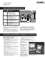
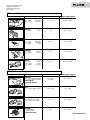
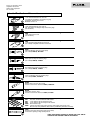
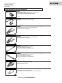
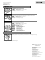
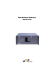
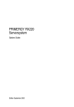
Page 1 of 8, Document #2320 ScopeMeter® 190C/190B Series and ScopeMeter® 120 Series ©2002 Fluke Corporation Rev. C-12/2002 ScopeMeter ® 190C/190B Series and ScopeMeter ® 120 Series Technical Data ANAGEMENT S YM Y IT EM ST QU AL ScopeMeter 190C and 190B Series: Speed, performance and analysis power RT 90 01 CE IF IE D TO MEET IS O R For demanding applications, the ScopeMeter 190C and 190B Series high-performance oscilloscopes offer specifications usually found on top-end bench instruments. With up to 200 MHz bandwidth, 2.5 GS/s real time sampling and a deep memory of 27,500 points per input they’re ideal for engineers who need the full capabilities of a high-performance scope in a handheld, battery powered instrument. • • • • • • Dual input - 200, 100 or 60 MHz bandwidth Up to 2.5 GS/s real time sampling per input Connect-and-View™ automatic triggering, a full range of manual trigger modes plus external triggering Digital Persistence for analyzing complex, dynamic signals like on an analog oscilloscope (190C) Fast display update rate for seeing dynamic behavior instantaneously Automatic capture and replay of 100 screens • • • • • • 27,500 points and more per input record length using ScopeRecord™ mode TrendPlot™ paperless recorder for trend analysis up to 22 days 1,000 V CAT II and 600 V CAT III safety certified Waveform reference for visual comparison and automatic pass/fail testing (190C) of waveforms Up to 1,000 V independently floating isolated inputs Four hours rechargeable NiMH battery pack ScopeMeter 120 Series: Three-in-one simplicity The compact ScopeMeter 120 Series is the rugged solution for industrial troubleshooting and installation applications. It’s a truly integrated test tool, with oscilloscope, multimeter and “paperless” recorder in one affordable, easy-to-use instrument. Find fast answers to problems in machinery, instrumentation, control and power systems. • A dual input 40 MHz or 20 MHz digital oscilloscope • Two 5,000 counts true-rms digital multimeters • • • Cursor measurements (Fluke 124) • Shielded test leads for oscilloscope, resistance, continuity and capacitance measurements • Full bandwidth, VPS40 10:1 40 MHz probe included standard with Fluke 124 • Up to seven hours battery operation • • 600 V CAT III safety certified • Rugged, compact case A dual input TrendPlot recorder Connect-and-View trigger simplicity for hands-off operation Optically isolated RS-232 interface Page 2 of 8, Document #2320 ScopeMeter® 190C/190B Series and ScopeMeter® 120 Series ©2002 Fluke Corporation Rev. C-12/2002 Technical Specifications 190C and 190B Series Oscilloscope Mode Vertical Deflection Bandwidth Rise time Fluke 199C Fluke 199B 200 MHz 1.7 ns Fluke 196C Fluke 196B 100 MHz 3.5 ns Fluke 192B 60 MHz 5.8 ns Bandwidth limiter: User selectable: 10 kHz, 20 MHz or off Number of inputs: 2 plus external trigger. All inputs isolated from each other and ground. Input coupling: AC or DC, with ground level indicator Input sensitivity: 2 mV/div to 100 V/div (Fluke 190C Series); 5 mV/div to 100 V/div (Fluke 190B Series) Variable attenuator: Variable gain on input channel A Input voltage: 1000 V CAT II, 600 V CAT III rated See “general specifications” for further details. Vertical resolution: 8 bit Accuracy: ± (1.5% of reading + 0.04 x range/div) Input impedance: 1 MΩ ± 1% // 15 pF ± 2 pF Horizontal Maximum real-time sample rate Number of digitizers Time base range Fluke 199C Fluke 199B 2.5 GS/s Fluke 196C Fluke 196B 1 GS/s Fluke 192B 500 MS/s 2 2 2 5 ns/div to 5 s/div 10 ns/div to 5 s/div Maximum record length: 1,200 points per input in Scope mode; 27,500 points per input in ScopeRecord™ roll mode (5 ms/div to 2 min/div) Accuracy: ± (0.01 % of reading + 1 pixel) Glitch capture: 50 nsec (at 5 µsec/div to 1 min/div); 250 nsec (at 2 min/div) Display and Acquisition Fluke 199C Fluke 199B Fluke 196C Fluke 196B Fluke 192B Display 144 mm (5.67˝) full 144 mm (5.67˝) color LCD monochrome LCD Display modes Input A, input B, dual, Input A, input B, dual, average, invert, replay, average, invert, Digital Persistence mode replay, persistence (short/medium/ (on/off) long/infinite) Visible screen width: 12 divisions in scope mode Waveform mathematics: A + B, A - B, A * B, all with user selectable scaling of resultant; A versus B (X - Y-mode) Acquisition modes: Normal, auto, single shot, ScopeRecord™ roll, glitch capture, waveform compare, waveform compare with automatic “Pass / Fail testing” (in 199C and 196C only) Trigger and Delay Source: Input A, input B, external trigger input. All input references isolated from each other and from ground Modes: Automatic Connect-and-View,™ free run, single shot, edge, delay, video, video line, selectable pulsewidth Connect-and-View™: Advanced automatic triggering that recognizes signal patterns, automatically sets up and continuously adjusts triggering, time base and amplitude. Automatically displays stable waveforms of complex and dynamic signals like motor drive and control signals. Video triggering: NTSC, PAL, PAL+, SECAM. Includes field 1, field 2 and line select. Pulse width triggering: Pulse width qualified by time. Allows for triggering <t, >t, =t, ≠t, where t is selectable in minimal steps of 0.01 div. or 50 nsec. Time delay: One full screen of pre-trigger view or up to 100 screens (1200 divisions) of post-trigger delay Automatic Capture of 100 Screens The instrument ALWAYS memorizes last 100 screens (no user interaction or setup required). When an anomaly occurs on screen, the HOLD button can be pressed to review the full screen sequence over and over. Instrument can be set up for triggering on glitches or intermittent anomalies and will operate in “baby-sit” mode and will capture 100 events. Alternatively, the 199C and 196C can be set up in waveform compare mode to store only matching (“Pass”) or only non-matching (“Fail”) acquired waveforms in the replay memory bank for further analysis. Replay: Manual or continuous replay. Displays the captured 100 screens as a “live” animation. Each screen is labelled with date and timestamp. The contents can also be viewed by manually scrolling backwards and forwards “screen by screen.” Replay storage: Up to 2 sets of 100 screens each can be saved for later recall and analysis Waveform Compare and Pass/Fail Testing Waveform compare: Provides storage and display of a reference waveform for visual comparison with newly acquired waveforms. Reference is derived from an acquired waveform and can be modified in the ScopeMeter or externally using FlukeView® Software. Pass/Fail Testing (199C, 196C): In waveform compare mode, the Color Scopemeter can be set up to store only matching (“Pass”) or only non-matching (“Fail”) acquired waveforms in the replay memory bank for further analysis. Automatic Scope Measurements Vdc, Vac rms, Vac+dc, Vpeak max, Vpeak min, Vpeak to peak, Aac, Adc, Aac+dc, frequency (Hz), risetime, falltime, power factor, Watts, VA, VA reactive, phase, pulse width (pos/neg), dutycycle (pos/neg), temperature °C, temperature °F, dBV, dBm into 50 Ω and 600 Ω Vpwm ac, Vpwm ac+dc for measurement on pulse width modulated motordrives and frequency inverters Cursor Measurements Source: Input A, input B or the Mathematical Result trace Dual horizontal lines: Voltage at cursor 1 and 2, voltage between cursors Dual vertical lines: Time between cursors, 1/T between cursors (in Hz), voltage between markers, risetime with markers, falltime with markers Single vertical line: Min-Max and Average voltage at cursor position Zoom: Up to 8x horizontal zoom Page 3 of 8, Document #2320 ScopeMeter® 190C/190B Series and ScopeMeter® 120 Series ©2002 Fluke Corporation Rev. C-12/2002 Meter Mode Recorder Mode Via 4 mm banana inputs. Fully isolated from scope inputs and scope ground. The specified accuracy is valid over the temperature range 18 °C to 28 °C (65 °F to 82 °F). Add 10 % of specified accuracy for each degree C below 18 °C or above 28 °C. Maximum Resolution: 5,000 counts Voltmeter Ranges: 500 mV, 5 V, 50 V, 500 V, 1,000 V Accuracy: Vdc ± (0.5 % + 5 counts) Vac true rms 15 Hz...60 Hz: ± (1 % + 10 counts) 60 Hz...1 kHz: ± (2.5 % + 15 counts) Vac+dc true rms dc...60 Hz: ± (1 % + 10 counts) 60 Hz...1 kHz: ± (2.5 % + 15 counts) Ohms: Ranges: 500 Ω, 5 kΩ, 50 kΩ, 500 kΩ, 5 MΩ, 30 MΩ Accuracy: ± (0.6 % + 5 counts) ScopeRecord-Roll Mode Other Meter Functions Continuity: Beeper on < 50 Ω (± 30 Ω) Diode test: Up to 2.8 V Amps: Adc, Aac, Aac+dc using an optional current clamp or shunt Scaling factors: 0.1 mV/A ... 100 V/A Temperature (°C, °F): With optional accessories. Scale factors 1 mV/°C or 1 mV/°F Input impedance: 1 MΩ ± 1% // 10 pF ± 2 pF Advanced meter functions: Auto/manual ranging, relative measurements (Zero reference), TrendPlot recording Dual input waveform storage mode Source and display: Input A, Input B, Dual Memory depth: 27,500 points per input or more. Each point consists of Min-Max pair Min-Max values: Min-Max values are measured at high sample rates ensuring capture and display of glitches Time base range Recorded timespan Glitch capture Sample rate Resolution 5 ms/div to 1 min/div 6 sec to 24 hr 50 ns 20 MS/s 200 µsec to 2 sec 2 min/div 48 hr 250 ns 4 MS/s 4.8 sec Recording modes: Single sweep, continuous roll, Start-on-Trigger, Stop-on-Trigger Stop-on-Trigger (through external): ScopeRecord mode can be stopped by an individual trigger event, or by an interruption of a repetitive trigger signal Horizontal scale: Time from start, time of day Zoom: Up to 100x Memory: Up to 2 dual input ScopeRecord waveforms can be saved for later recall and analysis TrendPlot™ recording Single or dual input electronic paperless chart recorder. Plots, displays and stores meter and scope measurements. Source and display: Input A, Input B or DMM input Memory depth: 18,000 points recording. Per record point a minimum, a maximum and an average value, plus a date and timestamp are recorded. Ranges: 5 s/div to 30 min/div in normal view mode; 5 min/div to 48 hr/div in view all mode, giving overview of total record Recorded timespan: Up to 22 days with a resolution of 1 minute Recording mode: Continuous roll for the duration of the full recordable timespan Measurement speed: 5 measurements per second Horizontal scale: Time from start, time of day Zoom: Up to 64x zoom Memory: Up to 2 TrendPlot recordings can be saved for later recall and analysis Cursor measurements - all recorder modes Source: Input A, B or DMM input Dual vertical lines: Min-Max or Average voltage. Time between cursors Single vertical line: Min-Max or Average voltage. Absolute date and time or time from start Page 4 of 8, Document #2320 ScopeMeter® 190C/190B Series and ScopeMeter® 120 Series ©2002 Fluke Corporation Rev. C-12/2002 General Specifications Safety Case Compliance: EN61010-1 (1993) Pollution degree 2 UL 3111-1 (1994) CAN/CSA C22.2 No.1010.1 (1992) ANSI/ISA S82.01 (1994) Design: Rugged, shock proof with integrated protective holster Drip and dust proof: IP51 according to IEC529 Shock and Vibration: Shock 30 g, Vibration (sinusoidal and random) 3 g according to MIL-PRF-28800F Class 2 Display Fluke 199C, 196C Bright full-color LCD with CCFL backlight, 80 (30) Cd/m2 with (without) power adapter Fluke 199B, 196B, 192B Bright monochrome LCD with CCFL backlight, 125 (75) Cd/m2 with (without) power adapter Display size: 115.2 x 86.4 mm (4.54 x 3.4 in.) Resolution: 320 x 240 pixels Contrast and brightness: User adjustable, temperature compensated Memory Save and Recall Scope memories: 10 memory locations that each can contain two waveforms plus corresponding setup Recorder memories: 2 memory locations that each can contain 100 captured dual input scope screens, or a dual input ScopeRecord (27,500 Min-Max pairs per input), or a dual input Trendplot (18,000 min-max pairs + average values) Real-Time Clock Time and date stamp for ScopeRecord, 100 captured screens and TrendPlots Power Input Voltage Ratings Maximum probe voltage: 1,000 V CAT II/600 V CAT III (Maximum voltage between 10:1 probe tip (VPS200) and reference lead) Floating voltage: 1,000 V CAT II/600 V CAT III (Maximum voltage between earth ground and any terminal (signal input or shielding)) Independently isolated inputs: 1,000 V CAT II/600 V CAT III (Maximum voltage between any terminal of one input or probe (VPS200) and any other terminal of another input or probe (VPS200)) Maximum voltage on BNC input directly (input A or B): 300 V CAT III Maximum voltage on meter input: 1,000 V CAT II/600 V CAT III Environmental Operating temperature: 0 °C to +50 °C Storage temperature: -20 °C to +60 °C Humidity: 10 °C to 30 °C: 95% RH non condensing 30 °C to 40 °C: 75% RH non condensing 40 °C to 50 °C: 45% RH non condensing Maximum operating altitude: 3,000 m (10,000 feet) Maximum storage altitude: 12 km (40,000 feet) Electro-Magnetic-Compatibility (EMC): EN 61326-1 for emission and immunity Line power: Country specific line voltage adapter/battery charger included Battery power: Rechargeable NiMH (installed) Battery operating time: 4 hours Battery charging time: 4 hours Battery power saving functions: Auto power down with adjustable power down time. On screen battery power indicator PC communication: Transfer instrument settings, screen images, waveform data and waveform references, compatible with FlukeView® software for Windows® via optional PM9080. To printer: Supports HP Laserjet®, DeskJet, Epson FX/LQ and Postscript printers via optional PAC 91 Mechanical Data Warranty Size: 256 x 169 x 64 mm (10.1 x 6.6 x 2.5 in) Weight: 2 kg (4.4 lbs) 3 years, parts and labor on mainframe instrument 1 year on accessories Optically Isolated PC / Printer Interface Accessories Standard Accessories Rechargeable battery pack (installed) Line voltage adapter / Battery charger Voltage probes and accessories Multimeter test leads User manual Fluke 199C, Fluke 196C, Fluke 199B, Fluke 196B, Fluke 192B BP190 BC190 10:1 voltage probe (VPS200, 1 red + 1 grey) including hook clip, ground lead with mini alligator clip, ground lead with hook clip, 4 mm add-on probe tip, ground lead to 4 mm banana plug TL75 Hard Point test lead set (1red, 1 black) 9 language versions on CD-ROM, “Getting Started” booklet included with instrument Page 5 of 8, Document #2320 ScopeMeter® 190C/190B Series and ScopeMeter® 120 Series ©2002 Fluke Corporation Rev. C-12/2002 Technical Specifications ScopeMeter 120 Series Oscilloscope Mode Cursor Measurements (124 only) Vertical deflection Sources: Input A, Input B Modes: Single or dual vertical cursor, dual horizontal cursor, rise- or falltime Measurements: Single vertical line: Average, min value, max value, time from start of recording in roll mode Dual vertical lines: ∆V at markers, time between cursors, 1/T between cursors (in Hz) Dual horizontal lines: High, low or ∆V - readout, rise- and falltime: transition time, 0 %-level, 100 %level, with markers at 10 % and 90 % Accuracy: As oscilloscope Bandwidth and Risetime Fluke 124 Fluke 123 Bandwidth (risetime) • with VPS40 probes • input A and B directly • with STL120 Shielded Test Leads 40 MHz 40 MHz 12.5 MHz 20 MHz 20 MHz 12.5 MHz Instrument risetime (input directly) 8.75 ns 17.5 ns Number of inputs: 2 Input coupling: AC, DC with ground level indicator Input sensitivity: 5 mV to 500 V/div (with the included VPS40 (Fluke 124) and STL120 shielded test leads measure up to 600 Vrms, CAT III) Input voltage: 600 V CAT III. See General Specifications for more detailed information Vertical resolution: 8 bit Accuracy: ± (2 % of reading + 0.05 x range/div) Input impedance: 1 MΩ ±1 % // 225 pF with STL120 shielded test leads; 1 MΩ ±1 % // 20 pF ± 3 pF with BB120; 5 MΩ ±1 % // 15.5 pF with VPS40, 10:1 Voltage probe Horizontal Max. sample rate (both channels simultaneously): Fluke 124: 2.5 GS/s for repetitive signals; 25 MS/s for single shot Fluke 123: 1.25 GS/s for repetitive signals; 25 MS/s for single shot Number of digitizers: 2 Time base range: 10 ns/div to 1 min/div (Fluke 124); 20 ns/div to 1 min/div (Fluke 123) Maximum record length: 512 Min-Max points per input Accuracy: ± (0.1 % of reading + 1 pixel) Glitch detect: 40 ns Display and acquisition Display modes: Input A, input A and B, envelope, smooth Acquisition modes: Normal (including glitch capture), single shot, roll Trigger and delay Source: Input A, input B, external via optional ITP120 Modes: Automatic Connect-and-View, Free Run, Edge, Single Shot, Video, Video Line Connect-and-View: Advanced automatic triggering that recognizes signal patterns and automatically sets up and continuously adjusts triggering, time base and amplitude. Automatically displays stable pictures of complex and dynamic signals like motor drive and control signals Video triggering: NTSC, PAL, PAL+, SECAM. Includes line select Time delay: Up to 10 divisions pre-trigger view Measurements Vdc, Vac, Vac+dc, Vpeak max, Vpeak min, Vpeak to peak, frequency (Hz), positive pulse width, negative pulse width, positive duty cycle, negative duty cycle, Amp ac, Amp dc, Amp ac+dc, Phase, Temperature °C, Temperature °F, dBV, dBm into 50 Ω and 600 Ω. (Amps, °C or °F with optional probes) Dual Input Meter The specified accuracy is valid over the temperature range 18 °C to 28 °C (64 °F to 82 °F). Add 10 % of specified accuracy for each °C below 18 °C or above 28 °C (64 °F to 82 °F) Max. meter bandwidth: 40 MHz (Fluke 124), 20 MHz (Fluke 123) Voltage measurements Measurement selection: Vdc, Vac rms, Vac+dc rms, Vpeak max, Vpeak min, Vpk-pk Ranges: 500 mV, 5 V, 50 V, 500 V, 1250 V Full scale reading: 5,000 counts Accuracy Vdc: ± (0.5 % + 5 counts) Vac rms: 1 Hz to 60 Hz: ± (1 % + 10 counts) 60 Hz to 1 kHz: ± (2.5 % + 15 counts) 20 kHz to 1 MHz ± (5 % + 20 counts) Vac+dc true-rms: DC to 60 Hz: ± (1 % + 10 counts) 60 Hz to 1 kHz: ± (2.5 % + 15 counts) 20 kHz to 1 MHz (5 % + 20 counts) Vpeak: Max peak or Min peak: 5% of full scale Peak-to-peak: 10% of full scale Ohms Ranges: 500 Ω, 5 kΩ, 50 kΩ, 500 kΩ, 5 MΩ, 30 MΩ Max. resolution: 5,000 counts Accuracy: ± (0.6 % of reading + 5 counts) Capacitance Ranges: 50 nF to 500 µF Max. resolution: 5,000 counts Accuracy: ± (2 % of reading + 10 counts) Other meter functions Frequency: Up to 70 MHz (Fluke 124) or up to 40 MHz (Fluke 123) Continuity: Beeper on < 30 Ω Diode test: Up to 2.8 V Amps: Amp dc, Amp ac, Amp ac+dc using an optional current clamp or shunt. Scaling factors: 0.1 mV/Amp to 100 V/Amp Temperature (°C, °F): With optional accessories. Scale factors 1 mV/°C or 1 mV/°F Number of inputs: 2 Input impedance: 1 MΩ ± 1 % // 10 pF ± 2 pF Advanced meter functions: Auto/manual ranging, TouchHold®, Relative measurements (zero reference), TrendPlot recording Page 6 of 8, Document #2320 ScopeMeter® 190C/190B Series and ScopeMeter® 120 Series ©2002 Fluke Corporation Rev. C-12/2002 Recorder Mode Mechanical data Trendplot recording Size: 50 x 115 x 232 mm (2 x 4.5 x 9.1 in) Weight: 1.2 kg (2.64 lbs) Dual input electronic paperless chart recorder. Plots and displays the actual, minimum, maximum and average of any measurement. Source and display: Input A, Input A and B Range: 15 s/div to 2 days per division (automatic) Recorded timespan: Up to 16 days with a resolution of 1.5 hours Recording mode: Continuous with automatic vertical scaling and horizontal time compression Measurement speed: 2.5 measurements per second maximum Horizontal scale: Time from start General Specifications Case Design: Rugged, shock proof with integrated protective holster Drip and dust proof: IP51 according to IEC529 Shock and vibration: Shock 30 g Vibration 3 g (sinusoidal) according to MIL-PRF-28800F Class 2 Display Bright LCD with CCFL backlight, 60 (35) cd/m2 with (without) power adapter Size: 72 x 72 mm (2.8 x 2.8 inch) Resolution: 240 x 240 pixels Contrast and brightness: User adjustable, temperature compensated Memory Save and Recall 20 (10 in Fluke 123) instrument screens with user set-ups and user text Real-time clock Time and date stamp TrendPlot recording Power Line power: Country specific line voltage adapter/battery charger included Battery power: Rechargeable Ni-MH BP130 (installed in Fluke 124) or rechargeable NiCd BP120 (installed in Fluke 123) Battery operating time: Up to 7 hours using BP130, up to 5 hours using BP120 Battery charging time: 5 hours (Fluke 123), 7 hours (Fluke 124) Battery power saving functions: Auto power down with adjustable power down time. On-screen battery power indicator Safety Compliance: EN61010.1 (1993) Pollution degree 2, UL3111-1 (1994), CAN/CSA-C22.2 No. 1010.1 (1992), ANSI/ISA S82.01 (1994) Input voltage ratings Maximum input voltage: 600 V CAT III (Maximum voltage between input and reference lead) Maximum input voltage using VPS40 Probe: 600 V CAT III, 1000 V CAT II (Maximum voltage between probe tip input and reference lead) Floating voltage: 600 V CAT III (Maximum voltage between earth ground and any terminal (signal input or reference lead)) Maximum voltage between reference leads: Instrument has common grounds connected via self recovering fault protection. For different ground potential measurements between inputs use DP120 differential voltage probe Environmental Operating temperature: 0 °C to +50 °C Storage temperature: -20 °C to +60 °C Humidity: 10 °C to 30 °C, 95% RH non condensing; 30 °C to 40 °C, 75% RH non condensing; 40 °C to 50 °C, 45% RH non condensing Maximum operating altitude: 2,000 m (6,500 feet); 3,000 m (10,000 feet) voltages ≤ 400 V Maximum storage altitude: 12 km (40,000 feet) Electro-Magnetic Compatibility: Emission EN50081-1 (EN55022 and EN60555-2) Immunity EN50082-2 (IEC1000–4-2, -3, -4, -5) Optically isolated PC/Printer interface To printer: Supports HP Laserjet,® Deskjet,® Epson FX/LQ and postscript printers via optional PAC91 To PC: Transfer instrument settings, screen images and data, compatible with FlukeView® software for Windows® via optional PM9080 Warranty 3 years, parts and labor on mainframe instrument 1 year on accessories Accessories Standard Accessories Rechargeable battery pack (installed) Line voltage adapter / Battery charger Voltage probes and accessories Multimeter test leads User manual Fluke 123, Fluke 124 BP120 (Fluke 123), BP130 (Fluke 124) PM8907 STL120 Shielded Test lead set; VPS40 high impedance 10:1 probe, 40 MHz (1 black, included with Fluke 124 only); HC120 hook clips; ground leads with mini alligator clips; AC120 alligator clips; BB120 BNC-to-Shielded banana adapter TL75 Hard Point test lead (1 black) 14 language versions on CD-ROM, “Getting Started” booklet included with instrument Page 7 of 8, Document #2320 ScopeMeter® 190C/190B Series and ScopeMeter® 120 Series ©2002 Fluke Corporation Rev. C-12/2002 International Safety Standards Overvoltage Category CAT IV CAT III CAT II CAT I Summary description Three phase at utility connection, any outdoors conductors (under 1,000 V) • Outside and service entrance • Service drop from pole to building • Run between meter and panel • Overhead line to detached building • Underground line to well pump Three-phase distribution (under 1,000 V), including single phase commercial lighting and distribution panels • Feeders and short branch circuits • Distribution panel devices • Heavy appliance outlets with “short” connections to service entrance Single-phase receptable connected loads • Outlets and long branch circuits • All outlets at more than 10 m (30 ft) from Category III source • All outlets at more than 20 m (60 ft) from Category IV source Electronic • Electronic equipment • Low energy equipment with transient limiting protection To protect your instrument and – more importantly – yourself, choose a test tool that can withstand the electrical hazards present in the environment in which you plan to use it. EN61010 establishes international safety requirements for electrical measurement equipment. It separates the various electrical environments into installation categories based on the danger from high voltage-energy transients. To choose the right tool, the voltage rating alone does not determine the safety. It is the combination of voltage rating and installation category that determines maximum transient withstand capability of the tool. CAT III rated instruments are recommended for measurement on industrial power distribution systems. FlukeView® ScopeMeter® Software for Windows® FlukeView software adds PC power to your Fluke ScopeMeter Test Tools. FlukeView ScopeMeter software helps you get more out of your ScopeMeter: • Store instrument’s screen copies on the PC, in color (with Fluke 190C Series) or in black and white (Fluke 190B and 120 Series) • Copy color screen images into your reports and documentation (color screen images with Fluke 190C Series only) • Capture and store waveform data from your ScopeMeter on your PC • Create and archive waveform references for automatic (Fluke 190C Series) or visual (Fluke 190B and 190C Series) comparison • Use cursors for parameter measurement • Includes waveform analysis, e.g., FFT spectrum analysis • Copy waveform data into your spreadsheet for detailed analysis • Extended recording of up to four user-selected measurements help you monitor and analyze slow moving signals and related events • Logging of other readings directly into other application programs, eg., spreadsheet • • • Add user text to instrument setups and send these to the instrument for operator reference and instructions Capture complete Replay sequence into the PC for further analysis and documentation English, French and German versions included on a single CD-ROM Note: Some functionality may be available with specific ScopeMeter models only System requirements • • • • • Pentium 90 or better CD-ROM drive Windows® 95 / 98 / Me / NT 4.0 / 2000 / XP One free RS 232 port PM9080 Optically isolated RS 232 adapter/cable, available separately or included in SCC190/SCC120 kit and in ScopeMeter ‘S’ versions Supported Instruments Full support for Fluke 199C, 199B, 199, 196C, 196B, 196, 192B, 192, 124, 123 Page 8 of 8, Document #2320 ScopeMeter® 190C/190B Series and ScopeMeter® 120 Series ©2002 Fluke Corporation Rev. C-12/2002 Selection Guide Bandwidth Max real time sample rate Max equivalent time sample rate Display Digital persistence Envelope mode Waveform compare 190C Color ScopeMeter Series Fluke 199C Fluke 196C 200 MHz 100 MHz 2.5 GS/s 1 GS/s 190B ScopeMeter Series Fluke 199B Fluke 196B Fluke 192B 200 MHz 100 MHz 60 MHz 2.5 GS/s 1 GS/s 500 MS/s — 144 mm full color LCD Yes, gives analog oscilloscope like waveform decay (user selectable) Yes Visual reference and automatic ‘Pass / Fail’ testing Fluke 120 Series Fluke 124 Fluke 123 40 MHz 20 MHz 25 MS/s 2.5 GS/s 144 mm monochrome LCD 1.25 GS/s 102 mm monochrome LCD — — Yes Visual reference Yes — Max record length in Scope Mode: 1200 points per input channel 512 min/max points per input in ScopeRecord mode: 27,500 points per input or more (5 ms/div to 2 min/div) — Number of inputs 2 plus external / DMM input, all isolated from each other and from ground 2 Number of digitizers 2 2 Independently floating Up to 1000 V between inputs, references and ground — isolated inputs Input sensitivity 2 mV/div to 100 V/div 5 mV/div. to 100 V/div 5 mV/div to 500 V/div Glitch capture Up to 3 ns using pulse width triggering; 50 ns peak detect at 5 ms/div to 1 min/div 40 ns Timebase range in Scope mode 5 ns/div to 2 min/div 10 ns/div to 10 ns/div to 20 ns/div to 2 min/div 1 min/div 1 min/div Trigger types Connect-and-View™, Free Run, Single Shot, Edge, Delay, Video Frame, Connect-and-View™, Free Run, Video Line, Selectable Pulse Width and External Single Shot, Edge, Video Scope measurements 7 cursor measurements, 30 automatic measurements cursors + 26 26 automatic automatic measurements measurements Waveform mathematics A + B, A - B, A x B, A versus B (X-Y-mode, giving Lissajous diagrams) — ScopeRecord trigger modes Start on trigger, stop on trigger — Capture last 100 screens Automatic, with replay capability — Dual input TrendPlot Yes, with cursors and zoom Yes Memory for screens and 10 screens with set-up; set-ups 5 more memories are made available upon registration of the ScopeMeter 20 10 Memory for recordings Two, each can store 100 scope screens, a ScopeRecord or a TrendPlot True-rms multimeter 5000 counts, Volts, Amps, Ohms, Continuity, Diode, Temp Safety certified (EN61010-1) 1000 V CAT II / 600 V CAT III (instrument and included accessories) 600 V CAT III (instrument and included accessories) Battery (installed) 4 hr Ni-MH BP190 7 hr NiMH 5 hr NiCd Line Power Adapter / battery-charger included Size 25 x 16.9 x 6.4 cm (10.1 x 6.7 x 2.5 in) 232 x 115 x 50 mm (9.2 x 4.5 x 2 in) Weight 2 kg (4.4 lb) 1.2 kg (2.64 lbs) PC and Printer Interface Using optional optically isolated RS-232 adapter/cable Warranty 3 years on main instrument, 1 year on the standard accessories Detailed technical specifications and optional accessories can be found on the Fluke web site. There, you can also download a fully-functional instrument which is based on the real instrument firmware. Check it out at: www.fluke.com/scopemeter. Ordering Information Fluke-199C/S Color ScopeMeter (200 MHz / 2.5 GS/s) with SCC190 kit Fluke-199C Color ScopeMeter (200 MHz / 2.5 GS/s) Fluke-196C/S Color ScopeMeter (100 MHz / 1 GS/s) with SCC190 kit Fluke-196C Color ScopeMeter (100 MHz / 1 GS/s) Fluke-199B/S ScopeMeter (200 MHz / 2.5 GS/s) with SCC190 kit Fluke-199B ScopeMeter (200 MHz / 2.5 GS/s) Fluke-196B/S ScopeMeter (100 MHz / 1 GS/s) with SCC190 kit Fluke-196B ScopeMeter (100 MHz / 1 GS/s) Fluke-192B/S ScopeMeter (60 MHz / 500 MS/s) with SCC190 kit Fluke-192B ScopeMeter (60 MHz / 500 MS/s) Fluke-124/S Industrial ScopeMeter, 40 MHz, with SCC120 kit Fluke-124 Industrial ScopeMeter, 40 MHz Fluke-123/S Industrial ScopeMeter, 20 MHz, with SCC120 kit Fluke-123 Industrial ScopeMeter, 20 MHz BP120 Rechargeable NiCd Battery for use with Fluke 120 Series BP130 BP190 SW90W PM9080 SCC190 SCC120 C195 C190 C125 C120 DP120 VPS40 Rechargeable NiMH Battery for use with Fluke 120 Series Rechargeable NiMH Battery for use with Fluke 190 Series ScopeMeters FlukeView ScopeMeter Software for Windows Optically isolated RS232 adapter/cable Software - Cable - Case kit for Fluke 190 Series Software - Cable - Case kit for Fluke 120 Series Durable, universal soft carrying case for ScopeMeters and accessories Hard shell protective carrying case for Fluke 190 Series ScopeMeters Durable, protective soft carrying case for Fluke 120 Series ScopeMeters Hard shell protective carrying case for Fluke 120 Series ScopeMeters Differential Voltage Probe for use with Fluke 120 Series 40 MHz, 10:1 Voltage probe set for use with Fluke 120 Series Fluke. Keeping your world up and running. Fluke Corporation PO Box 9090, Everett, WA USA 98206 Fluke Europe B.V. PO Box 1186, 5602 BD Eindhoven, The Netherlands For more information call: In the U.S.A. (800) 443-5853 or Fax (425) 446-5116 In Europe/M-East/Africa +31 (0) 40 2675 200 or Fax +31 (0) 40 2675 222 In Canada (800)-36-FLUKE or Fax (905) 890-6866 From other countries (425) 446-5500 or Fax (425) 446-5116 Web access: http://www.fluke.com Page 1 of 6, Document #2321 ScopeMeter Accessories ©2001 Fluke Corporation Rev. A-9/2001 ScopeMeter® Accessories PC Software SW90W FlukeView® ScopeMeter® Software for Windows® • For Fluke 190 & 120 Series ScopeMeter • Windows® 95/98 NT 4.0/2000 • Requires one free RS-232 port (COM port) • Optional PM9080 RS-232 Adapter/Cable required SCC120 Software Cable Case 120 Series SCC190 Software Cable Case 190 Series Accessories Package, including: • FlukeView® ScopeMeter® Software for Windows® English, French and German languages • PM9080 Optically Isolated RS-232 Adapter/Cable • Hard Carrying Case C120 or C190 Protective Cases C120 Hard Carrying Case for 120 Series C190 Hard Carrying Case for 190 Series Storage compartments for test leads, probes, instruction manual, power adapter and other small accessories. C195 Soft Carrying Case Universal Durable soft case. Adjustable storage compartments suitable for all ScopeMeter models. Storage compartments for test leads, probes, instruction manual, power adapter and other accessories. C125 Compact Soft Case 120 Series Zippered carrying case (black) for 120 Series. Pouch is designed to carry test leads and probes. Convenient belt loop accommodates tool belt. Powering and Charging − + PM8907 Line Voltage Adapter/Battery Charger 120 Series BC190 Line Voltage Adapter/Battery Charger 190 Series /801 (Europe) 230 V ± 10% /803 (North America) 120 V ± 10% /804 (United Kingdom) 230 V ± 10% /806 (Japan) 100 V ± 10% /807 (Australia) 230 V ± 10% /808 (Universal) switchable 115 V± 15% or 230 V ± 15% Page 2 of 6, Document #2321 ScopeMeter Accessories ©2001 Fluke Corporation Rev. A-9/2001 Safety Designed Oscilloscope Probes Double insulated, 600V CAT III / 1000V CAT II rated Type / Description Attenuation Max. Signal Voltage Band Width 10:1 1000 V 200 MHz 10:1 1000 V 200 MHz VPS201 ➀➁ 100:1 Voltage Probe Set (red and gray) 100:1 1000 V 200 MHz VPS250 ➀ 2.5 m Voltage Probe Set (red and gray) 10:1 1000 V 75 MHz VPS121 ➀ 1:1 Voltage Probe Set probe (one black) 1:1 300 V 12 MHz VPS200-G Voltage Probe Set (one gray) ➀➁ VPS200-R Voltage Probe Set (one red) ➀➁ Probe sets include: ➀ 600 V CAT III / 1000 V CAT II rated Voltage Probe 1.2 m; Hook Clip for Probe Tip; 4 mm Test Probe for Probe; Ground Lead with Hook Clip; Ground Lead with Mini Alligator. ➁ 30 V CAT II rated Ground Spring for Probe Tip DP120 Differential probe 1.5 m with shrouded banana probe tips (red and black) 600V CAT III / 1000V CAT II rated 200:1 20:1 1200 Vp 120 Vp 20 MHz 20 MHz ITP120 Optically isolated trigger probes 1.2 m, for ScopeMeter 123. Incl. Hookclip with ground lead. Max. signal voltage & voltage to ground: 600 V rms, CAT II Safety Designed Oscilloscope Probe Accessories For VPS Series probes AS200-G Probe Accessory Set Gray AS200-R Probe Accessory Set Red Set includes: 600 V CAT III / 1000 V CAT II rated Industrial Alligator for Probe; 2 mm Test Probe for Probe; 2 mm Test Probe for Banana; Industrial Alligator for Banana; Ground Lead 4 mm Banana RS200 Probe Replacement Set Set includes: 600 V CAT III / 1000 V CAT II rated Hook Clip for Probe Tip (2 red, 1 gray); 4-mm Test Probe for Probe (1 red, 1 gray); Ground Lead with Hook Clip(1 red, 1 gray); Ground Lead with Mini Alligator (2 black). 30 V CAT II rated Ground Spring for Probe Tip (5x). PM9090 Pin-grabber (red and gray) Maximum Voltage: 600 V rms. CAT III Page 3 of 6, Document #2321 ScopeMeter Accessories ©2001 Fluke Corporation Rev. A-9/2001 AC Current Clamps Range ! i200s 0.1 – 20 A 0.5 – 200 A ➂ 100 mV/A 10 mV/A ➂ 1 mV/A 80i-500s 1 – 500 A Basic Accuracy % reading Usable Frequency Range 1.5% + 0.5 A 40 Hz – 10 kHz 2% 5 Hz - 10 kHz i1000s 0.1 – 10 A 0.1 – 100 A 1 – 1000 A ➂ 100 mV/A 10 mV/A 1 mV/A 1% + 1 A 5 Hz – 100 kHz i2000flex 2 – 200 A 20 – 2000 A ➂ 10 mV/A 1 mV/A 1% F.S. 1 Hz – 20 kHz i3000s 1A – 30 A 1A – 300 A 1A – 3000 A ➂ 10 mV/A 1 mV/A 0.1 mV/A 2% + 2 A 10 Hz – 100 kHz Basic Accuracy % reading Usable Frequency Range 3% + 50 mA (@ 10A) DC – 100 kHz 3.5% + 0.5 A DC - 3 kHz 2% + 0.5 A DC – 10 kHz 0.1% DC - ≥10 kHz FLEX CUR AC IBLE RENT PRO BE BATT ERY POW LOW ER AND UT INPUT OUTP ON 0 FLE 1 mV/A mV/A OFF A 10 2000 A 200 i200 X AC / DC Current Clamps Type Ranges 0V 60 i410 ➂ 1 A – 400 A; AC/DC 1 mV/A 0V 60 i1010 ➂ 1 A – 600 A; AC 1 mV/A 1 A – 1000 A; DC 1 mV/A T CA 0V 60 0AA 6000 10 AC /D C OU RO 0 ZE A 01AM i1 CL T V/A EN 1m : RR UT CU TP P T CA III T CA 0V 60 0A 40 AC /D C OU RO ZE A 10 i4CLAM T V/A EN 1m : RR UT CU TP P T CA III 80i-110s 0.1 - 10 A; AC/DC 100 mV/A 1 – 100 A; AC/DC 10 mV/A 600 V CAT II, 300 V CAT III rated CS20MA 4 - 20 mA shunt 10 Ω 10 mV/mA 30 V CAT III rated ➂ 600 V CAT III rated Page 4 of 6, Document #2321 ScopeMeter Accessories ©2001 Fluke Corporation Rev. A-9/2001 Industrial Test Leads and Accessories STL120 1.2 m Industrial Shielded Test Lead Set 12.5 MHz for ScopeMeter 120 Series (red, gray) Compatible with AC120 & HC120 Maximum current: 1A ➃ TL20 1.6 m Industrial Silicone Test Lead Set Incl. Test Probes and Alligator Clips for banana plugs (red and black) ➄ TL24 1.6 m Silicone Test Leads (red and black) ➄ TL75 1.2 m Hard Point Right Angle Test Lead Set (red & black) Compatible with AC120 & HC120 ➄ UL 1244 AC20 Industrial Alligator Clips for banana plugs (red & black) 1000 V, 10 A max. AC80 Hook-Style Test Clips for banana plugs (red & black) 1000 V, 3 A max. AC83 Pin-Grabber Test Clips for banana plugs (red & black) 1000 V, 1 A max. AC85A Large Jaw Alligator Clips for banana plugs (red & black) 600 V, 10 A max. AC120 Alligator Clips 120 (red, gray, black) For STL 120 and TL75 Test Leads 600 V, 10 A max. HC120 Hook Clips 120 (red, gray) For STL 120 and TL75 Test Leads 600 V, 3 A max. Slim Reach™ Test Probes for banana plugs (red & black) ➄ TP1 Flat blade for North American wall sockets TP2 2 mm diameter tip for electronics work TP4 4 mm diameter tip for European wall sockets TP38 With insulated tips TP74 Lantern tip banana-style spring contacts with nickel-plated brass ends Meet GS-38, safety Guidance Note issued by UK Ministry of Health and Safety TP80 Electronic Test Probe for banana plugs (red & black) For electronic probing of high density boards ➄ ➃ Max. Signal Voltage & Voltage to Ground: 600 V rms. CAT III ➄ Rated for 10 A and 1000 V CAT III environments Page 5 of 6, Document #2321 ScopeMeter Accessories ©2001 Fluke Corporation Rev. A-9/2001 Safety Designed Cables and Adapters PAC91 Printer Adapter Cable 0.25 m Safety designed optical to parallel printer adapter cable See instrument Manual for compatible printers PM9080 Optically-isolated RS-232 Interface Adapter male PM9081 Dual banana plug 4 mm male to female BNC Adapter The set consists of two adapters ➅ PM9082 Dual banana jack 4 mm female to male BNC Adapter The set consists of two adapters ➅ PM9091 50 Ohm Coaxial BNC cable set, 3 x 1.5 m Three colored BNC male connectors (red, gray and black) for easy identification ➅ PM9092 50 Ohm Coaxial BNC cable set, 3 x 0.5 m Three colored BNC male connectors (red, gray and black) for easy identification ➅ PM9093 Male BNC to dual female BNC T-piece Set consists of two adapters ➅ female female male 0.5m V9092-42 BB120 ➅ Two shielded Banana-to-BNC Adapters Adapting Probes and BNC adapters to 120 Series ScopeMeters ➅ Max Signal Voltage: 300 V rms CAT III Max Voltage to Ground: 600 V rms. CAT III Page 6 of 6, Document #2321 ScopeMeter Accessories ©2001 Fluke Corporation Rev. A-9/2001 Temperature Probes 80T-150U Universal Temperature Probe For air, surface, and non-corrosive liquids Range: -50 ºC to + 150 ºC, or –58 ºF to 320 ºF Output: 1 mV per ºC or ºF Accuracy: ±1 ºC (1.8 ºF) 0 ºC to 100 ºC 0UROB 15 RE P T- RATU 80TEMPE E OF °F F °C 80T-IR Non-Contact Infrared Temperature Probe For hazardous to touch, moving, easily contaminated, or difficult to reach surfaces Range: -18 ºC to +260 ºC, or 0 ºF to 500 ºF Output: 1 mV per ºC or ºF Accuracy: ±3% of reading (+3 digits) 80T-IR INFRARED TEMPERATURE PROBE 0 to 500° F –18 to 260° C E R TKRATU 80TEMPE 80TK Thermocouple Module For Type K thermocouples with connector Range: -50 ºC to +1000 ºC, or –58 ºF to 1832 ºF Output: 1 mV per ºC or ºF Accuracy: 0.5% ±2 ºC, or 0.5% ±3.6 ºF Optional probes for 80TK 80CK-M Male Mini Connectors 80PK-1 K-Type General Purpose Probe 80PK-2A K-Type Immersion Probe 80PK-3A K-Type Surface Probe 80PK-4A K-Type Air Probe 80PK-5A K-Type Piercing Probe 80PK-6A K-Type Exposed Probe 80PK-7 K-Type Industrial Surface Probe 80PK-8 K-Type Pipe Clamp Probe E B O R P OF °F F °C Pressure Probes PV350 Digital Pressure/Vacuum Module Measures pressure to 500 psi (3447 kPa) and vacuum from 0 to 76 cm Hg (0 to 29.9” Hg) 0 35 PV i • ps Hg F a• cm kP OF g in H UM AU /V RE SU ES PR LE DU MO EN IC TR ME ISH GL ZE RO All ratings per IEC 1010-2-032, Pollution Degree 2 Fluke. Keeping your world up and running. Fluke Corporation PO Box 9090, Everett, WA USA 98206 Fluke Europe B.V. PO Box 1186, 5602 BD Eindhoven, The Netherlands For more information call: In the U.S.A. (800) 443-5853 or Fax (425) 446-5116 In Europe/M-East/Africa (31 40) 2 675 200 or Fax (31 40) 2 675 222 In Canada (800) 36-FLUKE or Fax (905) 890-6866 From other countries (425) 446-5500 or Fax (425) 446-5116 Web access: http://www.fluke.com/