1
SCSI BUS ANALYZER
Model # U l t r a - 2 0 8 0
USER=S MANUAL
Revision 2.1
June 1999
Ancot Corporation
115 Constitution Drive
Menlo Park, California 94025
(650) 322-5322
COMPANY PROFILE
Ancot Corporation designs and manufactures SCSI and Fibre Channel development and test equipment,
and other computer products for OEM markets, based on the SCSI, Fibre Channel, and Gigabit Ethernet
protocols. Ancot=s instruments are used worldwide by leading computer companies. Applications include
development, manufacturing, and repair. Ancot=s policy is to provide quality products, and to support its
customers with qualified engineering support to maximize the return on their investment.
Document No. 20032-021
8 Copyright 1998, 1999 by Ancot Corporation
ANCOT Corporation
User=s Manual
SCSI Bus Analyzer Ultra-2080
CONTENTS
SECTION 1 DESCRIPTION OF EQUIPMENT...........................................................1-1
1.1 Introduction..........................................................................................................1-1
1.2 General Description.............................................................................................1-2
1.3 System Overview................................................................................................1-3
1.4 Timing Conditions in Recording...........................................................................1-4
1.5 Front Panel (Ultra-2080/Bxx)..............................................................................1-5
1.6 Notational Conventions .......................................................................................1-7
1.7 User Interface......................................................................................................1-8
1.7.1 Local Mode Operation ..............................................................................1-8
1.7.2 Remote Mode Using Serial Port ...............................................................1-9
1.7.3 Remote Mode Over Ethernet Using Browser ...........................................1-9
1.7.4 Menus.....................................................................................................1-10
1.7.5 Other General Rules .............................................................................1-11
1.8 Timer ................................................................................................................1-11
1.9 Electrical Connection on the SCSI Bus .............................................................1-11
1.10 SCSI Bus Termination and Termination Power................................................1-12
1.11 Technical Specifications...................................................................................1-12
1.12 SCSI Standard Specifications and References ................................................1-14
1.12.1 SCSI Standard Specifications ..............................................................1-14
1.12.2 Other Literature ....................................................................................1-15
1.12.3 Internet Resources ...............................................................................1-15
SECTION 2 FUNCTIONS AND COMMANDS...........................................................2-1
2.1 Introduction..........................................................................................................2-1
2.2 Trace Memory .....................................................................................................2-2
2.3 File.......................................................................................................................2-4
2.3.1 Save Trace ...............................................................................................2-5
2.3.2 Restore Trace...........................................................................................2-6
2.3.3 Save Setup...............................................................................................2-6
2.3.4 Restore Setup ..........................................................................................2-7
2.3.5 Send Trace...............................................................................................2-7
2.3.6 Receive Trace ........................................................................................2-10
2.3.7 File Management....................................................................................2-11
2.3.8 Print ........................................................................................................2-13
2.3.9 DOS Shell...............................................................................................2-13
ANCOT Corporation
User=s Manual
SCSI Bus Analyzer Ultra-2080
2.4
Tracing ..............................................................................................................2-17
2.4.1 Run.........................................................................................................2-18
2.4.2 Stop ........................................................................................................2-18
2.4.3 Display Trace .........................................................................................2-18
2.4.4 Pause .....................................................................................................2-18
2.4.5 Find ........................................................................................................2-19
2.4.6 Trace Mode Setup Options ....................................................................2-19
2.4.7 Trigger Options.......................................................................................2-22
2.4.8 Set Display Format .................................................................................2-22
2.4.9 Time Calculation.....................................................................................2-22
2.5 Utilities...............................................................................................................2-24
2.5.1 Show System Configuration ...................................................................2-24
2.5.2 Clear Trace Memory...............................................................................2-25
2.5.3 Restore Factory Defaults........................................................................2-25
2.5.4 Load New Firmware ...............................................................................2-25
2.5.5 Serial Port Settings.................................................................................2-26
2.5.6 Remote Control Using Ethernet Port ......................................................2-27
2.5.7 Remote Control Using Serial Port ..........................................................2-29
2.5.8 Time and Date Settings..........................................................................2-30
2.5.9 The Screen Saver ..................................................................................2-30
2.6 SCSI Initiator Emulator ......................................................................................2-31
2.7 Help ...................................................................................................................2-32
SECTION 3 DISPLAYING THE TRACE MEMORY ..................................................3-1
3.1 Introduction..........................................................................................................3-1
3.2 The Structured Display Format............................................................................3-3
3.2.1 Structured Display with Narrow or Wide Data Transfers ..........................3-4
3.2.2 Structured Display with Narrow Data Transfers........................................3-6
3.2.3 Structured Display of SCAM Protocol.......................................................3-7
3.3 The Binary Display Format ..................................................................................3-7
3.3.1 Binary Display of the SCAM Protocol ......................................................3-12
3.4 The Hex Dump Format ......................................................................................3-14
3.5 The Compact Display Format............................................................................3-14
3.6 The Command Profile Format ...........................................................................3-15
3.7 Changing the Display Format ............................................................................3-16
SECTION 4 SEARCHING FOR EVENTS IN THE RECORDED TRACE ..................4-1
4.1 Introduction..........................................................................................................4-1
ANCOT Corporation
User=s Manual
SCSI Bus Analyzer Ultra-2080
4.1.1 Select a Custom Control Bit Pattern.........................................................4-2
4.2 Select the Search Options...................................................................................4-4
4.2.1 Search for Wide Data Pattern ..................................................................4-4
4.2.2 Set the Search Direction ..........................................................................4-5
4.2.3 Set the Occurrence Counter.....................................................................4-5
4.2.4 Set the Search Address Limits .................................................................4-5
4.2.5 Set the Search Starting Address ..............................................................4-5
4.2.6 Set the Data Bits Pattern..........................................................................4-6
4.3 Repeating the Search..........................................................................................4-6
SECTION 5 TRIGGERING........................................................................................5-1
5.1 Introduction..........................................................................................................5-1
5.2 Trigger Options ...................................................................................................5-1
5.3 Trigger Examples ................................................................................................5-4
5.3.1 Late Triggering .........................................................................................5-4
5.3.2 Early Triggering ........................................................................................5-5
5.3.3 No Trigger Required .................................................................................5-7
SECTION 6 SCSI INITIATOR EMULATION .............................................................6-1
6.1 Introduction..........................................................................................................6-1
6.2 SCSI Initiator Emulation . ....................................................................................6-1
6.2.1 <^A> Change LBA ....................................................................................6-3
6.2.2 <^B>, <^L> Macros...................................................................................6-3
6.2.3 <^D> Data Buffer Management ................................................................6-4
6.2.4 <^E> Edit CDB..........................................................................................6-4
6.2.5 <^F>, <^G> Increment LBA After Wt/Rd...................................................6-5
6.2.6 <^H> Autofill .............................................................................................6-5
6.2.7 <^I> Initiator ID .........................................................................................6-6
6.2.8 <^K> Compake Buffers ............................................................................6-6
6.2.9 <^N> Link & Flag Bit .................................................................................6-6
6.2.10 <^R> SCSI Reset .....................................................................................6-7
6.2.11 <^T> Target ID..........................................................................................6-7
6.2.12 <^U> Logical Unit (LUN) ...........................................................................6-7
6.2.13 <^X> Emulator Setup................................................................................6-7
6.2.14 <^Y> Queue Tag ......................................................................................6-8
6.2.15 <^Z> Repeat Command ...........................................................................6-8
6.3 <^D> Data Buffer management ...........................................................................6-9
6.3.1 <^0> Select Buffer .....................................................................................6-9
ANCOT Corporation
User=s Manual
SCSI Bus Analyzer Ultra-2080
6.2.2 <^1> View & Edit Buffer...........................................................................6-10
6.2.3 <^2> Fill Buffer ........................................................................................6-10
6.2.4 <^3> Copy Byffer ......................................................................................6-11
6.2.5 <^4> Set Buffer Size................................................................................6-11
6.4 <^X> Emulator Setup.......................................................................................6-12
6.4.1 <^0> Allocation/Transfer Lengths ............................................................6-12
6.4.2 <^1> Arbitration .......................................................................................6-13
6.4.3 <^2> Identify Message.............................................................................6-13
6.4.4 <^3> Disconnect/Reconnect....................................................................6-14
6.4.5 <^4> Custom Message............................................................................6-14
6.4.6 <^5> Data protocols.................................................................................6-14
6.4.7 <^6> Mode Sense/Mode Select...............................................................6-16
6.4.8 <^7> Target Type ....................................................................................6-17
6.4.9 <^8> SCSI Version ..................................................................................6-17
6.4.10 <^9> Timeout Selection ...........................................................................6-17
SECTION 7 INSTALLATION .....................................................................................7-1
7.1 Unpacking ...........................................................................................................7-1
7.2 Initial Turn-on ......................................................................................................7-1
7.3 Initial Checkout ....................................................................................................7-2
7.4 Communication, Interfacing, and Setup ..............................................................7-2
7.5 EPROM Upgrades...............................................................................................7-3
7.6 Firmware Upgrades (Flash Memory) ...................................................................7-4
7.7 Floppy Disk Drive Installation .............................................................................7-5
APPENDIX A EXTERNAL CONNECTOR PINS AND CABLES .............................. A-1
A.1 I/O Interface Connectors..................................................................................... A-1
A.2 Auxiliary Connectors ........................................................................................... A-2
A.3 Single-Ended and LVD 68-pin Connectors ......................................................... A-3
A.4 Differential HVD 68─pin Connectors................................................................... A-4
APPENDIX B ESCAPE SEQUENCES FOR SCREEN CONTROL ......................... B-1
B.1 General ............................................................................................................... B-1
B.2 Escape Sequences - Out (From Ultra-2080 to Terminal).................................... B-2
B.3 Escape Sequences - In (From Terminal to Ultra-2080)....................................... B-2
ANCOT Corporation
User=s Manual
SCSI Bus Analyzer Ultra-2080
APPENDIX C TRACE UPLOAD / DOWNLOAD FORMATS ................................... C-1
C.1 Header / Trailer Information ................................................................................ C-1
C.2 Raw Data Format................................................................................................ C-2
C.2.1 Natural SCSI Events ................................................................................ C-2
C.2.2 Artificial SCSI Events ............................................................................... C-5
C.3 Readable Formats .............................................................................................. C-8
APPENDIX D THE SCAM PROTOCOL .................................................................. D-1
D.1 General ............................................................................................................... D-1
D.2 Using the Ultra-2080 SCSI Bus Analyzer for SCAM ........................................... D-2
D.2.1 Activating the SCAM Display ................................................................... D-2
APPENDIX E USING THE PC & PROCOMM or Win95 HYPERTERMINAL .......... E-1
E.1 Remote Control - Using the PROCOMM............................................................. E-1
E.1.1 Setting Up PROCOMM Options............................................................... E-1
E.1.2 Save Trace to Host ................................................................................. E-4
E.1.2.1 ASCII Transfer .............................................................................. E-4
E.1.2.2 Xmodem Transfer ......................................................................... E-5
E.1.3 Restore Trace from Host ......................................................................... E-5
E.1.3.1 ASCII Transfer .............................................................................. E-5
E.1.3.2 Xmodem Transfer ......................................................................... E-6
E.2 Remote Control - Using the Win95 HYPERTERMINAL ..................................... E-7
APPENDIX F SCSI FACTS AND TIPS .....................................................................F-1
F.1 General ................................................................................................................F-1
F.2 Cabling .................................................................................................................F-1
F.3 Electrical Connection and Termination on the SCSI Bus .....................................F-1
F.3.1 Single-Ended Alternative...........................................................................F-2
F.3.2 High Voltage Differential - HVD Alternative ...............................................F-3
F.3.3 Low Voltage Differential - LVD Alternative ...............................................F-3
F.4 The Terminator Power: TERMPWR.....................................................................F-4
F.5 SCSI Initiators & Targets....................................................................................F-4
F.6 SCSI Device Addressing .....................................................................................F-5
F.7 SCSI Data Parity .................................................................................................F-5
F.8 Mixing SE & Diff SCSI Devices ...........................................................................F-6
F.9 Mixing SE & LVD SCSI Devices..........................................................................F-6
F.10 SCSI Cable Length..............................................................................................F-6
F.11 Extending the SCSI Cable...................................................................................F-6
ANCOT Corporation
User=s Manual
SCSI Bus Analyzer Ultra-2080
ANCOT Corporation
User=s Manual
SECTION
SCSI Bus Analyzer Ultra-2080: Section 1
1
DESCRIPTION OF EQUIPMENT
1.1
INTRODUCTION
The Ultra-2080 is a portable, advanced, versatile, user-configurable SCSI Bus Analyzer. This
instrument was designed for the following applications:
- development work in the laboratory
- production test
- field service applications
The Ultra-2080 Analyzer provides a comprehensive SCSI event tracer, a debugger with powerful
triggering capability, and an optional SCSI initiator emulator. It provides displays of SCSI bus
activity in a variety of formats for easy interpretation.
The Analyzer comes in the following configurations:
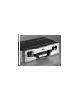
The Ultra-2080/Bxx is the briefcase model, and the Ultra-2080/Lxx which uses an
external PC host for control. The /Lxx models do not have a screen nor keyboard.
Both versions come with a circular trace buffer holding up to 128k events standard,
and optional 256k or 512k events.
The model numbers used for the Ultra-2080 are as follows:
Ultra-2080/mse where:
m = Model
B - briefcase version
L - ALite@ version (no screen or keyboard)
s = Memory Size
D - standard 128k trace events
K - optional 256k trace events
X - optional 512k trace events
e = Emulator option
E - emulator is installed
<blank> - no emulator is installed
1-1
ANCOT Corporation
User=s Manual
SCSI Bus Analyzer Ultra-2080: Section 1
An optional external floppy disk is also available (OP-XFL).
Examples:
Ultra-2080/BD - Standard briefcase model with 128k trace events.
Ultra-2080/BX - Briefcase model with optional 512k trace events.
Ultra-2080/BXE - Briefcase model with optional 512k trace events and emulator
1.2 GENERAL DESCRIPTION
The SCSI Bus Analyzer is used for recording activity on the SCSI Bus to which it is connected
non-intrusively. Its circular buffer can hold up to 128k events (standard for Ultra-2080/BDx),
256k or 512k events (optional). The recording method is event driven; only valid data or
transitions on certain SCSI signals are recorded. At the time of recording, each event is
time-stamped. The recording can later be played back in several forms. It can be displayed on a
built-in LCD flat screen, or sent to a printer to provide a hard copy. Recorded data can be
uploaded to a host computer, and saved on a disk to build a data base for post processing.
The display of recorded SCSI bus activity can be in several forms: "binary" format similar to a
time-domain form of logic analyzers, "structured" format which is an interpreted "SCSI-English"
form, easily understandable, Acompact@ showing one SCSI command per line, etc.
1-2
ANCOT Corporation
User=s Manual
SCSI Bus Analyzer Ultra-2080: Section 1
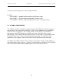
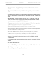
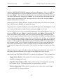
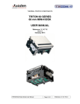
1.3 SYSTEM OVERVIEW
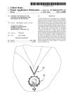
A simplified block diagram of the Ultra-2080 SCSI Bus Analyzer is shown below:
▐
▐
┌───────────────┐
▐
│
(optional) │
┌─────────────────┐
▐
│ SCSI Emulator │
│
│
▐>══════════>>
<═══════> SCSI Data Buffer│
▐
│ Symbios 53C895│
│ 8MB
│
▐
└──────────V────┘
└─────────V───────┘
▐
│
│
▐
│
│
▐ S
,,,,V,,,,,,,x,,,,,,,,,,,V,,,,
▐ C
┌───────┬────────┐ ▐ ┌───────┬────────┬───────┬────────┐
▐ S
│
│ Trace │ ▐ │
│Control │
│ Non│
▐ I
│Timer │ Memory │ ▐ │ MPU
│Program │Static │ Volat. │
▐
│
│128Kx72 │ ▐ │
│Flash
│RAM
│ EEPROM │
▐ B
│120
│ up to │ ▐ │
│
│
│
│
▐ u
│seconds│512Kx72 │ ▐ │ 68340 │1MB
│ 4MB
│ 8KB
│
▐ s
└───v───┴───v────┘ ▐ └───v───┴────v───┴───v───┴────v───┘
▐
│
│
▐
│
│
│
│
▐
│
│
▐
│
│
│
│
▐
,,,x,,,,x,,,,,,x,,,,,,x,,x,,,x,,,,,,,x,x,,,,x,,,x,,,x,,,,,
▐
│
│
Local bus
│
│
▐
│ ┌───────────┐
│
│
│
▐
│ │
│
│
┌─────x────────┐│
▐
│ │ SCSI Bus │
│
│Trigger/Filter││
▐>════════════>> Receivers >>═══════════════>>Circuits
││
▐
│ │
│
│
│
││
▐
│ └───────────┘
│
└/────/────────┘│
▐
┌──V──┐
│
│
│
┌─────V──┐
▐
│Dual x─────┐
│
│
│
│Parallel│
▐
│UART │
│
│
│
│
│ Port │
▐
└\──\─┘
│
│
│
│
└───\────┘
▐
│ │
┌──V──────────V─┐
│
│
│
(DB-25)
▐
│ │
│
│
│
│
└───<
Printer/Floppy
▐
│ │
│ FRONT PANEL
│
│
│
(BNC)
▐
│ │
│ w.Indicators, │
│
└─< Ext.Trigger Input
▐
│ │
│ EL screen,
│
│
▐
│ │
│ Keyboard
│
│
(BNC)
▐
│ │
│ Connectors
│
└──────< Ext.Synchr. Output
▐
│ │
└──────\──\──\──┘
▐
│ │
│ │ │
(DB-15)
▐
│ │
│ │ └──────────< Expansion Port Input
▐
│ │
│ └──────────< (RJ45) Ethernet 10/100
▐
│ │
│
(DIN5)
▐
│ │
(DB-9) └────< PC/AT Keyboard
▐
│ └──────< Serial-1 Port - mouse
▐
└─────────< Serial-2 Port
▐
▐ SCSI connectors 68-pin HD 'P' type for SCSI SE/LVD and HVD
1-3
ANCOT Corporation
User=s Manual
SCSI Bus Analyzer Ultra-2080: Section 1
The system carries out several major functions:
The Analyzer is connected to the SCSI bus by its line receivers. Note that the Analyzer is a
non-intrusive device, which merely senses activity on the SCSI bus through isolating receivers.
The load on the tested SCSI Bus is less than 25 pF.
From line receivers, the signals are directed to separate circuits: to trace memory, to the
trigger/filter circuitry, and to the front panel to be displayed using LED indicators. All parts of
the Ultra-2080 are internally controlled by the local MPU (Motorola's MC68340). The control
program for the MPU is saved in EPROM with 64KB capacity, and flash memory with 1MB
capacity.
Communication with the operator is by a built-in keyboard, and an LCD flat color screen display.
A parallel printer may be connected for hard copy output. In addition, a PC/AT type keyboard
and a mouse can be attached. The Analyzer can also be placed in 'Remote Control' mode,
controlled by an external PC or VT-100 type monitor.
Non-volatile EEPROM memory provides for storage of setup parameters, and user option
settings.
1.4 TIMING CONDITIONS IN RECORDING
Recording in the Trace Memory is event-driven. This means that only transitions on the SCSI
bus are recorded. A valid change (event) is determined by the tracing options, and is defined as
follows:
- a positive or negative transition on the BSY, SEL, ATN, and RST lines,
- during Information Transfer Phases, a SCSI event can be
a)
qualified by the valid edge of REQ or ACK signals:
During READ operations (Data from Target to Initiator), the status of SCSI bus
signals is recorded in Trace Memory following the leading edge of the REQ
signal. During WRITE operations (Data from Initiator to Target), the status of
SCSI bus signals is recorded following the leading edge of the ACK signal.
b)
recorded during any transition of the REQ or ACK signals, e.g., following all 4
edges of REQ and ACK.
1-4
ANCOT Corporation
c)
d)
User=s Manual
SCSI Bus Analyzer Ultra-2080: Section 1
recording of data during a Data-In or Data-Out phase can be skipped after the
leading bytes, up to 255. Note that all bytes transferred are counted, and the total
count will appear in the trace if the command completes successfully.
any transition on the MSG, C/D, or I/O SCSI Control lines can be recorded.
- the status of the SCSI bus and 3 external signals can be recorded on every negative
transition of bit 0 of the expansion port.
- certain changes on data lines when tracing the SCAM protocol and during the Arbitration
phase.
For more on trace recording modes read Section 2.4.6.
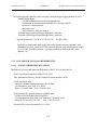
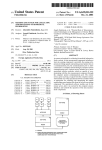
1.5
FRONT PANEL
The front panel of the Ultra-2080 contains a flat panel display screen, a keyboard, two pushbutton switches, and 36 LED indicator lights. Several connectors, a cooling fan, and the main
power switch module also share the front panel.
1-5
ANCOT Corporation
User=s Manual
1-6
SCSI Bus Analyzer Ultra-2080: Section 1
ANCOT Corporation
User=s Manual
Figure 1.
1-7
SCSI Bus Analyzer Ultra-2080: Section 1
ANCOT Corporation
User=s Manual
SCSI Bus Analyzer Ultra-2080: Section 1
The DISPLAY SCREEN is a high-visibility LCD flat panel, capable of displaying 25 lines of 80
characters.
The SYSTEM RESET switch restarts the system.
The SCSI RESET switch generates the RESET condition on the SCSI bus.
The LED indicators are:
POWER
TRACING
DISK ACTIVE
SCSI Control Signals: BUSY, SEL, C/D, I/O, MSG, REQ, ACK, RST and ATN
SCSI Data Signals: D0 - D15, and Data-Parity (2)
Single-Ended/LVD and Differential interface
TERMINATOR POWER (2)
CAPS LOCK
CONNECTORS located on the front panel are:
- Parallel Printer/Floppy (DB-25 female)
- Expansion 3-bit port Input (DB-15 female)
- two Serial I/O ports (DB-9 male for the mouse, DB-9 female for communication)
- 5-pin connector for PC/AT keyboard (DIN female)
- External Trigger Input (BNC connector)
- External Synch Output (BNC connector)
- J1,J2 - SCSI connectors (68-pin, female) for S-E/LVD interface
- J3,J4 - SCSI connectors (68-pin, female) for Diff HVD interface
-10/100 Mbit Ethernet (RJ-45)
EXTERNAL TRIGGER INPUT - The coaxial BNC type connector on the right side of the
front panel serves for input of an external trigger signal. The Ultra-2080 will trigger on positive
to negative transition if enabled from the trigger menu. External Trigger Input expects TTL level
signal.
The basic trigger functions, which most users would need, have been implemented in the system.
Additional unique trigger functions may be added by using this external trigger.
EXTERNAL SYNCH OUTPUT - The coaxial BNC type connector on the right side of the
front panel provides a trigger signal, which may be used for triggering external instruments such
as oscilloscopes, logic analyzers, etc. When a trigger occurs, this output generates positive to
negative transition. External Synch uses a TTL level.
EXPANSION 3-BIT PORT INPUT - There is often a need to compare the relationship of
external signals with the SCSI bus signals. For this purpose, the "Expansion" connector is
1-8
ANCOT Corporation
User=s Manual
SCSI Bus Analyzer Ultra-2080: Section 1
available. This input port allows for up to 3 signals to be recorded together with the SCSI trace.
This additional data, after being recorded, will be displayed as three "0" or "1" digits, in the
BINARY display mode. Pin 1 can be used as a clocking signal if "external clock" is enabled
from the recording mode menu.
See Appendix A for the Expansion connector pinout. Note that on this connector there are two
pins for Vcc (+5V, available up to 100mA), and two pins for GND. The Vcc and GND may be
used to power external devices such as AD converters, or other adapters.
AC POWER MODULE - consists of the AC main switch, fuse, and a three-pin receptacle for
the AC line cord. The fuse is accessible under a cover in the body of the module.
KEYBOARD - Note that the built-in keyboard and the external keyboard can be used interchangeably. You can be using both at the same time: press a key on the built-in keyboard, press
several keys on the external keyboard, go back to the built-in keyboard, etc.
The top row of keys on the built-in keyboard, corresponding to F1-F8 on the external keyboard,
have been labeled for the most common functions of the Ultra-2080. Use these keys for
shortcuts to common commands: Run, Stop, Display, etc.
10/100 Mbit ETHERNET PORT - This is a standard Ethernet port using an RJ-45 connector.
The hardware detects the proper speed when an Ethernet cable is connected. If you use 100
Mbit, make sure the cable is rated for 100 Mbit operation.
1.6 NOTATIONAL CONVENTIONS
The primary operator interface with the Ultra-2080 is through the keyboard on the front panel,
through the PC/AT keyboard, or through a mouse.. In this manual the following notation is used
when referring to keys and key sequences:
Keys are referred to by their legend, enclosed in angle brackets "<" and ">". Examples: < Esc >,
< Enter >, < Run >, < R >, < SP > (for "space") etc.
Keys to be depressed together (the "control combinations") are shown with a "^" (Up-Arrow)
preceding the other character. For example <^C> or <Ctrl-C> means that you type the "C" key
while the Ctrl key is depressed. Other combinations may also appear, as e.g., <Alt-C>, which
means type the "C" key while the <Alt> key is being depressed.
In menus or in various prompts, the optional suggested selections are displayed in parentheses.
Current selections or defaults are displayed in brackets "[", and "]".
1-9
ANCOT Corporation
User=s Manual
SCSI Bus Analyzer Ultra-2080: Section 1
1.7 USER INTERFACE
The Ultra2080 was designed to be controlled by the user in two ways: either locally or remotely.
In the LOCAL mode, the user uses the built-in screen, keypad or external keyboard and other
controls on the front panel of the unit.
In REMOTE mode, the user can connect an external (PC) host over the serial port and use
terminal emulation program (like PROCOM) in the host. He/she can also connect to a LAN
(using the RJ45 10/100baseT on the front panel) and control the Ultra2080 remotely using a
browser.
Both methods are described below.
1.7.1 LOCAL MODE OPERATION
The following controls are available to the user:
Flat 8.4" color flat panel screen, 73-key AT-compatible built-in keyboard, external keyboard,
switches and indicators listed below.
The operator interface from the keyboard is completely menu-driven. The main menu at the root
of the Ultra-2080 firmware system serves for selection of functions related to tracing, trigger
selection, and display of recorded data.
Most of the functions are actuated by a single key stroke; selection is recognized by the system,
and the rest of the word is filled in automatically. If the function doesn=t execute, more input is
needed, and a menu or prompt will appear on the screen. If a wrong key is pressed, the system
will either beep, and give the operator a second chance, or in some situations will abort and exit
that function. The type of each individual operation will determine which of the two actions will
be taken.
Several keys have characteristic functions:
Pressing <Enter>, <Space>, or <Yes> while at the root level, will re-display the main menu.
<Q> or <q> keys will cause exit from a current function, or exit the current menu, and stepping
one level back. By repeating the <Q> or <q>, eventually you will return to the main menu at the
root.
<Ctrl-C> There may be several prompts to be answered before a selected function is started. If
you change your mind in the middle of this selection process, then by pressing the <Ctrl-C> key
1-10
ANCOT Corporation
User=s Manual
SCSI Bus Analyzer Ultra-2080: Section 1
you can quit that selection sequence and exit immediately to the root. You can also use the
<Ctrl-C> to exit any selection and return directly to the root menu level.
<Pause> or <Ctrl-S> causes the system to pause. Press <Ctrl-Q> to continue.
<Ctrl-P> is a toggle switch that will turn "parallel printing" ON or OFF. The printing mode is
indicated by a message at the bottom of the main menu. "Parallel printing" means sending all
data displayed on the screen also to the printer port. Note that only the trace data will be printed,
not the menus, etc.
Note that the keys <Ctrl-C>, <Ctrl-S>, and <Ctrl-P> work the same as on any PC system.
1.7.2 REMOTE MODE OPERATION USING THE SERIAL PORT
Connect the external terminal (VT100 type terminal, PC, or other host running terminal
emulation program) to the DB-9 serial port connector on the front panel of the Ultra2080 using a
straight serial cable. You also may use a modem connection. We recommend that you follow
directions described in Appendix E. Once a serial connection has been established, you are able
to control the Ultra2080 through your remote terminal=s keyboard. Menu items may be selected
by using the highlighted letter or number or by using the arrow keys. Other sections in this
manual describe how to control tracing and display a trace.
1.7.3 REMOTE MODE OPERATION OVER ETHERNET USING A BROWSER
Configuring For The First Time
When starting your unit for the first time, you must use the serial interface. You may set up the
Ethernet port IP address and server options by using the Utilities menu (see section 2.5.6) if you
chose using the Ethernet interface.
Control Over the Ethernet Port using a Browser
After you have configured the Ethernet port (see section 2.5.6) as mentioned in the previous
paragraph, by assigning an IP address to the Ultra2080 and starting the web server, you may
control the Ultra2080 by using a web browser such as Netscape or Internet Explorer.
In Netscape=s ALocation:@ field or Internet Explorer=s AAddress:@ field, type Ahttp://@ followed by
the IP address which you have assigned to the Ultra2080. For instance if you assigned the IP
address 192.168.1.1 to the Ultra2080, type Ahttp://192.168.1.1" in the location or address field
and your browser will access the main page of the Ultra2080.
1-11
ANCOT Corporation
User=s Manual
SCSI Bus Analyzer Ultra-2080: Section 1
If you need to access files on the Ultra2080, start the FTP server and use and FTP client on your
computer (such as WS_FTP from Ipswitch). Choose the AC@ drive and a file/directory tree
should be displayed by your FTP program.
Do not delete any files in the Ahttp@ directory. These files are the web pages for the Ultra2080.
You may have to replace these from time to time as new pages become available from Ancot=s
web site. Do not delete the file Aancot.hlp@. This is the main helpfile for the briefcase version.
1.7.4 MENUS
The user interface is through: the screen and keyboard built into the front panel of the Ultra2080; an external keyboard connected to Serial-1; a mouse; or screen and keyboard of a remote
control PC/CRT.
The operator interface from the keyboard, or from the external PC/AT keyboard, is completely
menu-driven. The main menu at the root of the Ultra-2080 firmware system serves for selection
of functions related to tracing, trigger selection, and display of recorded data. See Ultra2080/LITE User=s Manual for menus used in the remote control mode.
The main functions are actuated by a single key stroke (<Alt> letter). A menu or prompt will
appear on the screen. If an incorrect key is pressed, the system will either beep, and give the
operator a second chance, or in some situations abort and exit that function. The type of each
individual operation will determine which of the actions will be taken.
Several keys have characteristic functions:
<Esc> will exit from a menu, and step one level back. By repeating <Esc> you will eventually
return to the main menu at the root. The <Esc> key from the keyboard has a similar effect.
There may be several prompts to choose from before you reach your selected function. If you
change your mind in the middle of this selection process, you can quit that selection sequence by
pressing <Esc>, or by selecting <Cancel>, and exit immediately to the previous menu.
<Pause> causes the system to pause. Press <Run> to continue.
<Home> selects the A<OK>@ button
<End> selects the A<Cancel>@ button
1-12
ANCOT Corporation
User=s Manual
SCSI Bus Analyzer Ultra-2080: Section 1
1.7.5 OTHER GENERAL RULES:
In edit sessions typically the current selection is displayed. If a different value is required, type it
in. If only <Enter> is typed, the current value will stay unchanged.
Numeric values, except the timing information (e.g., Time Stamp), are displayed in Hex format.
All numeric answers are expected to be in Hex unless marked otherwise.
Currently selected values are displayed in "[ ]" brackets. If such a value appears at the cursor for
input, typing <Enter> selects that value.
From menus displaying a highlighted entry, the arrow keys and the tab keys move the highlight
from one entry to the next. Most menu selections also have a "selector" key, which will move
the highlight directly to that entry.
1.8 TIMER
There is a 6-byte 50 MHZ counter in the Ultra-2080 Analyzer used for marking each recorded
event in trace memory with a time stamp. The resolution is 20 nanoseconds. The timer will
wrap around after approximately 213 days. The REQ/ACK signals are sampled each 1/5 cycle (4
ns) to give finer granularity resolution.
The time stamp is displayed together with the recorded data in the BINARY display format. It
can be selected to show as time differential (time increment from the previous event), or as time
elapsed from the beginning of the tracing. Make this selection on the keyboard by pressing <E>
while in the display mode. Timing information is also available in the STRUCTURED format
display. When enabled, the duration of each phase will be displayed on the last line of that
phase, if space permits.
1.9 ELECTRICAL CONNECTION ON THE SCSI BUS
There are three alternatives for connecting the SCSI bus: the SINGLE-ENDED and LVD (Low
Voltage Differential), and DIFFERENTIAL HVD (High Voltage Differential) connectors.
Pinouts of all connectors used are listed in Appendix A.
'SCSI FACTS & TIPS' in Appendix F is recommended reading for those interested in knowing
more about the various aspects of SCSI usage.
1-13
ANCOT Corporation
User=s Manual
SCSI Bus Analyzer Ultra-2080: Section 1
1.10 SCSI BUS TERMINATION AND TERMINATION POWER
No internal termination is provided. Use an external SCSI differential HVD or LVD, or singleended terminator. Power (TERMPWR) for this Terminator is supplied in all SCSI connectors.
TERMPWR is protected by a Schottky serial diode for protection against back flow, and by a 1.0
Amp fuse for protection against electrical short. The fuse acts as a circuit breaker with automatic
reset. In case of a short on TERMPWR, the breaker disconnects the circuit; when the short is
removed, the breaker restores TERMPWR within 20 seconds.
!!! WARNING !!!
NOTE THAT IF TERMPWR IS SUPPLIED BY MULTIPLE SOURCES TO
THE SCSI BUS, AND IF ACCIDENTALLY THE 'TERMPWR' PIN OF THE
SCSI BUS CABLE GETS GROUNDED, THEN THE 'TERMPWR' LEAD OF
THE SCSI BUS CABLE WILL HAVE TO WITHSTAND THE SUM OF THE
CURRENTS FROM ALL THE SOURCES 1 AMP EACH (EACH FUSED AT
1 AMP) BEFORE THE FUSES BEGIN TO BREAK !
As a rule, there should be exactly two terminators on a SCSI bus, one on each physical end.
Therefore, before connecting the analyzer to a system to be tested, see whether you should add
the terminator. This depends on where you are connecting the analyzer: in the middle or at
the physical end of the SCSI cable.
'SCSI FACTS & TIPS' in Appendix F is recommended reading for those interested in
knowing more about SCSI bus termination methods.
1.11 TECHNICAL SPECIFICATIONS
- Compatible with SCSI specifications as defined by the ANSI X3T9.2 committee for
SCSI-1 and SCSI-2, and the current draft SCSI-3 SPI/SIP, including Fast/40
- Asynchronous data transfer rates to over 6 MBps
- Synchronous data transfer rates to over 40M transfers per sec
- Three interfaces are standard: Single-ended (S-E), differential HVD (High Voltage
Differential), and LVD (Low Voltage Differential). All SCSI connectors are the 68-pin
female type for wide interface. Use a 68-to-50 pin adapter for the narrow interface.
1-14
ANCOT Corporation
User=s Manual
SCSI Bus Analyzer Ultra-2080: Section 1
- Non-intrusive tracer. Only signal changes are stored, therefore recording time is not
limited.
- Trace memory is 128K events deep and 48 bits wide. Optionally it can be expanded to
512K.
- Up to three external signals can be recorded together with SCSI in trace memory to allow
tracing in the tested device. External port pin 1 can be used as "clocking" (both edges are
used).
- Recording modes: record all; skip data; record one, two, or all four edges of REQ and
ACK; phase changes; capture expansion port changes; filtering by SCSI ID; recording
selections only; and recording SCSI-3 SCAM protocol
- Display of recorded trace data in several formats: in structured (Pascal-like) expanded or
compact form, binary, hexadecimal, or Command Profile format.
- Hard copy of all displays printed via parallel I/O port on an optional printer
- Event time-stamping function for more than 200 days before timer counter wrap around,
with 20 ns resolution (4 ns for REQ & ACK).
- Non-volatile EEPROM memory for storage of current setup and mode parameters
- 1 Mbyte system or program memory, and 8MByte data read/write SCSI buffer
- Motorola 68340 local MPU with resident firmware in 64K byte EPROM and 1MB
of flash memory.
- Configuration selectable through menu driven software, stored in non-volatile EEPROM
memory
- One 10/100 Mbit Ethernet port
-
One serial RS-232 I/O port with a selectable baud rate up to 115K with data format and
parity options
- One serial I/O port for a PC compatible serial mouse
1-15
ANCOT Corporation
User=s Manual
SCSI Bus Analyzer Ultra-2080: Section 1
- Powerful triggering capability, menu selectable: delayed-trigger (trigger position in trace)
Internal triggering by:
selected command, status or message pattern/code
combination of command and status and ID, or message and ID
(re)select, (re)select timeout
data parity error
Trace Memory is full (post-trigger)
External triggering through trigger-input BNC connector
External synch (trigger) output through a BNC connector
- Physical dimensions: 16.5"W x 12.5"D x 4.5"H.
-
1.12
1.12.1
Weight: 12 lbs
Housed in a transportable high-quality fan-cooled attaché case type enclosure, with
detachable top cover. Built-in LCD flat screen, keyboard, and switching power supply
for 110-220V 50-60Hz operation. A storage pouch for a small keyboard, cables,
adapters, etc.
SCSI SPECIFICATIONS AND REFERENCES
SCSI STANDARD SPECIFICATIONS
Mechanical, electrical and functional definitions of the SCSI-1 are described in:
SCSI-1 Specification Number: ANSI X3.131-1986
Title: Information Systems - Small Computer Systems Interface (SCSI)
Can be purchased from:
American National Standards Institute, Inc. (ANSI)
1430 Broadway, New York, N.Y. 10018
Phone: (212)642-4900 Fax: (212)302-1286
SCSI-2 and SCSI-3 Specifications are available from:
GLOBAL ENGINEERING DOCUMENTS
3130 South Harbor Blvd, Suite 330, Santa Ana, California 92704
(800)854-7179 or (303)792-2181
Fax: (303)792-2192
For the SCSI2, refer to document X3.131-1994.
1-16
ANCOT Corporation
User=s Manual
SCSI Bus Analyzer Ultra-2080: Section 1
1.12.2 OTHER LITERATURE
Basics of SCSI - Fourth Edition by Ancot
a quick introduction to SCSI, SCSI terms description, and glossary.
Available from Ancot Corporation
115 Constitution Drive, Menlo Park, CA 94025
Phone: (650) 322-5322
Fax: (650) 322-0455
Internet http://www.ancot.com
This publication is FREE
The Book of SCSI by Peter M. Ridge
contains chapters on anatomy of SCSI, connecting SCSI HW, installing SCSI in a PC,
troubleshooting, cables, ASPI programming, CAM, etc.
Available at many bookstores, or purchased directly from:
NO STARCH PRESS
1903 Jameston Lane, Daly City, CA 94013-3466
(415)334-7200
1.12.3 INTERNET RESOURCES
http://www.ancot.com
http://www.sta.com
http://www.symbios.com/T10
1-17
ANCOT Corporation
User=s Manual
1-18
SCSI Bus Analyzer Ultra-2080: Section 1
ANCOT Corporation
User=s Manual
SCSI Bus Analyzer Ultra-2080: Section 2
SECTION 2
FUNCTIONS AND COMMANDS
2.1 INTRODUCTION
Section 2 describes the commands you need most often for taking full advantage of the features
of the Ultra-2080 SCSI Bus Analyzer. The text information is closely related to the menu
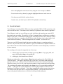
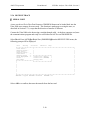
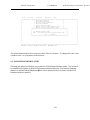
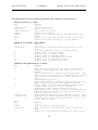
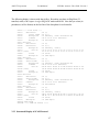
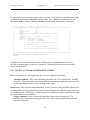
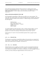
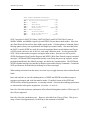
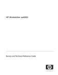
screens embedded in the system, and follows the same structure. The main menu, and most of
the subordinate menus following, show across the top line the four principal pull-down menus.
These four are the route to all commands and functions. Subsection 2.2 below describes the
trace memory in the Analyzer; the four succeeding subsections cover the use of the four main
pull-down menus: FILE, TRACING, UTILITIES, EMULATOR, and HELP. Each of these five
subsections describe the features and functions of the successive sub-menus they contain.
File Tracing Utilities Emulator Help
┌─────────────────────────────────────────────
└────────────────────────────────────────────────
TRACING: Stopped
TRIGGER: Disabled
PRINTER: Off
r=RUN s=STOP p=PAUSE d=DISPLAY ?=Help
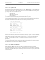
The main menu lists the pull-down menus of the Analyzer. To open one of the pull-down menus
from the keyboard, use <Alt-letter> where Aletter@ is highlighted on the pull-down menu. Another
way is to click on a pull-down menu with a mouse. As with all menus, selections can be made as
follows :
2-1
ANCOT Corporation
User=s Manual
SCSI Bus Analyzer Ultra-2080: Section 2
- Move the highlight bar to the desired entry using the arrows and press <Enter>.
- Press the selector key, shown by typing the highlighted character in the item text.
- Use the mouse and left-click on the selection.
- In some cases, use letter keys on the PC/AT keyboard as selector keys.
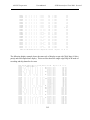
2.2 TRACE MEMORY
Trace Memory is a circular buffer 128K events deep, optionally 256K or 512K events deep, with
each event 48 bits wide. The content of trace memory is explained in more detail in Appendix C.
Trace Memory is used in a very efficient way: only valid data, and transitions on certain SCSI
bus signals cause recording. The qualifier for Data, Command, Status, and Message recording is
REQ or ACK strobe. In standard recording mode, when REQ for DATA-IN is asserted, or ACK
is asserted for Data Out, a snapshot of the SCSI bus (within less than 4 ns) is taken, latched, and
written in the trace memory. Other recording modes are available. See Section 2.4.6.
There are several SCSI control signals that cause recording whenever a transition on these is
detected. They are: RST, ATN, SEL, and BSY. Again, as with the data, a snapshot of the SCSI
bus is taken at the time of the transition (within 20 ns) and the event is subsequently recorded in
the trace memory.
The recording can be started or stopped in one of two ways:
a. - without trigger: operator starts recording by pressing <Run> or by typing <R>, and
stops it by pressing <Stop> or by typing <S>.
b. - with trigger, either immediate or delayed.
Whether recording with or without trigger, <Run> has to be used to set the Ultra-2080 in the
TRACING mode. This mode is indicated by the "TRACING" LED on the front panel and a
message on the screen. When activity on the SCSI bus starts, the trace memory starts filling.
When the memory is full, it will wrap around and continue writing from the physical beginning.
The recording will continue until stopped by the <Stop> key, or by a post-trigger condition, if
enabled. At that point the current (internal) trace memory physical address is detected, and
beginning of valid data is calculated. This is done automatically without operator intervention.
The earliest event still in the trace is at logical address 00000h. The operator does not have
access to the physical address however, but deals with logical addressing only.
2-2
ANCOT Corporation
User=s Manual
SCSI Bus Analyzer Ultra-2080: Section 2
When recording with trigger disabled (internal or external), the trace memory acts as a FIFO
buffer. The recording starts with the first SCSI activity following <Run>, and continues until
stopped by <Stop>. If trace memory (physical) capacity is exceeded, it wraps around and starts
writing from the physical beginning. Although the trace memory uses internally a linear physical
address space, the internal firmware translates physical address to logical before displaying it, to
make the trace memory appear circular. When recording is stopped, it reports "STOPPED AT
xxFFF(WRAP)". The last recorded event is at trace memory (logical) address 1FFFF (7FFFF in
512K versions).
When triggering is used, recording starts as described above, and continues until a trigger
condition occurs. When the trigger finally occurs, then depending on trigger position, the
recording either:
- stops immediately
- continues to the end of the current command when BUS-FREE Phase is detected
- or records a certain number of additional events before stopping (post trigger delay).
When External Trigger is used and the last location is filled, recording stops immediately.
TRACING will stop immediately, without delay, when <Stop> is pressed.
2-3
ANCOT Corporation
User=s Manual
SCSI Bus Analyzer Ultra-2080: Section 2
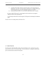
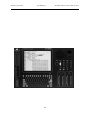
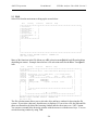
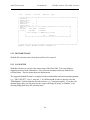
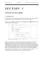
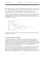
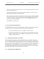
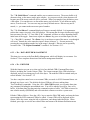
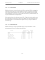
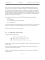
2.3 FILE
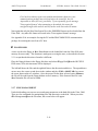
Select File from the main menu to bring up the screen below.
File
Tracing
Utilities
Emulator
Help
••••••••••••••••••••••••••••••••••••••••••••••••••••••••••••••••••••••••••••••••
• Save Trace...
•
•
• Restore Trace...
•
•
• Save Setup...
•
•
• Restore Setup...
•
•
• Send Trace
>>
•
•
• Receive Trace
>>
•
•
• File Management >>
•
•
• Print...
•
•
• DOS Shell
•
•
•••••••••••••••••••••••••
•
•
•
•
•
•
•
•
•
•
•
•
•
•
•
•
•
•
•
•
•
••••••••••••••••••••••••••••••••••••••••••••••••••••••••••••••••••••••••••••••••
TRACING: Stopped TRIGGER: Disabled
PRINTER: Off
Save trace to disk.
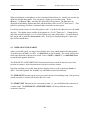
Many of the functions in the File Menu use a Afile selection menu@ which has different headings
depending on context. Example shown below is file selection menu for the ASave Trace@ menu
item.
File
Tracing
Utilities
Emulator
Help
••••••••••••••••••••••••••••••••••••••••••••••••••••••••••••••••••••••••••••••••
• Save Trace...
•
•
• Restor•••••••••••Save Trace: Select Destination Directory••••••••••••
•
• Save S•
•
•
• Restor• Active Drive (x) C: (hard drive) ( ) A: (floppy drive)
•
•
• Send T•
523,304,960 Bytes free
•
•
• Receiv•
Name
Size
Date
Time
Attrib
•
•
• File M•
••••••••••••••••••••••••••••••••••••••••••••••••••••••••• •
•
• Print.•
•TRACES
<DIRECTORY>
• •
•
• DOS Sh•
•SETUP
<DIRECTORY>
• •
•
•••••••••
•0830_000.TRC
370,688
08-30-98
02:19
• •
•
•
•
•
• •
•
•
•
•
• •
•
•
•
•
• •
•
•
•
•
• •
•
•
•
••••••••••••••••••••••••••••••••••••••••••••••••••••••••• •
•
•
• Path: C:\
•
•
•
•
•
•
•
•
< OK > <Cancel>
•
•
•
••••••••••••••••••••••••••••••••••••••••••••••••••••••••••••••••
•
•
•
••••••••••••••••••••••••••••••••••••••••••••••••••••••••••••••••••••••••••••••••
TRACING: Stopped TRIGGER: Disabled
PRINTER: Off
Use tab to exit.
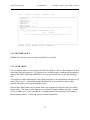
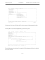
The file selection menu allows you to select the drive and has a window for browsing the file
system. If you select a directory, that directory is displayed. If you select a file, the path and file
name are shown directly below the browsing window and the cursor moves to < OK > button.
You can move around in the browsing window with the mouse or with the arrow keys. You can
exit the browsing window by using TAB.
2-4
ANCOT Corporation
User=s Manual
SCSI Bus Analyzer Ultra-2080: Section 2
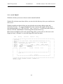
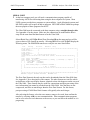
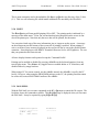
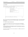
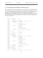
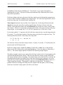
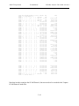
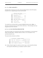
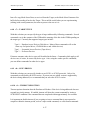
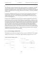
2.3.1 SAVE TRACE
With this selection you can save the trace on the internal hard disk.
With the file selection menu shown below you can select the directory where you want the trace
to be saved.
With the second menu shown below you can select the trace memory address range and
destination file name. The suggested default file name comprises the month and day and an
incrementing number, e.g., "0805_002.TRC" Aug. 5, trace no. 2. If a different path or name is
desired, select the "Path/filename" field and type the desired selection e.g..,
A\traces\mytrace.001@. If you have the optional floppy disk, you may also save the trace to the
floppy by using "a:\filename" or select the floppy disk in the first menu.
File
Tracing
Utilities
Emulator
Help
••••••••••••••••••••••••••••••••••••••••••••••••••••••••••••••••••••••••••••••••
• Save Trace...
•
•
• Restor•••••••••••Save Trace: Select Destination Directory••••••••••••
•
• Save S•
•
•
• Restor• Active Drive (x) C: (hard drive) ( ) A: (floppy drive)
•
•
• Send T•
523,304,960 Bytes free
•
•
• Receiv•
Name
Size
Date
Time
Attrib
•
•
• File M•
••••••••••••••••••••••••••••••••••••••••••••••••••••••••• •
•
• Print.•
•TRACES
<DIRECTORY>
• •
•
• DOS Sh•
•SETUP
<DIRECTORY>
• •
•
•••••••••
•0830_000.TRC
370,688
08-30-98
02:19
• •
•
•
•
•
• •
•
•
•
•
• •
•
•
•
•
• •
•
•
•
•
• •
•
•
•
••••••••••••••••••••••••••••••••••••••••••••••••••••••••• •
•
•
• Path: C:\
•
•
•
•
•
•
•
•
< OK > <Cancel>
•
•
•
••••••••••••••••••••••••••••••••••••••••••••••••••••••••••••••••
•
•
•
••••••••••••••••••••••••••••••••••••••••••••••••••••••••••••••••••••••••••••••••
TRACING: Stopped TRIGGER: Disabled
PRINTER: Off
Use tab to exit.
2-5
ANCOT Corporation
File
User=s Manual
Tracing
Utilities
Emulator
SCSI Bus Analyzer Ultra-2080: Section 2
Help
••••••••••••••••••••••••••••••••••••••••••••••••••••••••••••••••••••••••••••••••
• Save Trace...
•
•
• Restore Trace...
•
•
• Save Setup...
•
•
• Restore Setup...
•
•
• Send Trace
>>
•
•
• Receive Trace
>>
•
•
• File Ma•••••••••••••••••••••••••Save trace•••••••••••••••••••••••••••
•
• Print..•
•
•
• DOS She•
Start Addr
[00000000]
•
•
••••••••••
End Addr
[0000F0EF]
•
•
•
•
•
•
•
• Path/filename C:\TRACES\1112_000.TRC
•
•
•
•
•
•
•
•
< OK > <Cancel>
•
•
•
••••••••••••••••••••••••••••••••••••••••••••••••••••••••••••••
•
•
•
•
•
•
•
•
•
•
•
••••••••••••••••••••••••••••••••••••••••••••••••••••••••••••••••••••••••••••••••
TRACING: Stopped TRIGGER: Disabled
PRINTER: Off
2.3.2 RESTORE TRACE
With the file selection menu, select the trace(file) to be restored.
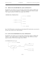
2.3.3 SAVE SETUP
With this selection you can save the current setup of the Ultra-2080. The setup includes
triggering and trace mode information. First, select the destination directory from the file
selection menu. The next menu shows the default name.
The suggested default file name is comprised of the month and day and an incrementing number,
e.g.., "0805_002.SET" Aug. 5, setup no. 2. If a different path or name is desired, select the
"Path/filename" field and type the desired selection, e.g.., \setup\mysetup.001. If you have the
optional floppy disk, you may also save the setup to the floppy by using "a:\filename" or by
selecting floppy disk in the file selection menu.
2-6
ANCOT Corporation
File
User=s Manual
Tracing
Utilities
Emulator
SCSI Bus Analyzer Ultra-2080: Section 2
Help
••••••••••••••••••••••••••••••••••••••••••••••••••••••••••••••••••••••••••••••••
• Save Trace...
•
•
• Restore Trace...
•
•
• Save Setup...
•
•
• Restore Setup...
•
•
• Send Trace
>>
•
•
• Receive Trace
>>
•
•
• File Management >>
•
•
• Print..•••••••••••••••••••••••••Save Setup ••••••••••••••••••••••••••
•
• DOS She•
•
•
•••••••••• Path/filename C:\SETUP\1112_000.SET
•
•
•
•
•
•
•
•
< OK > <Cancel>
•
•
•
••••••••••••••••••••••••••••••••••••••••••••••••••••••••••••••
•
•
•
•
•
•
•
•
•
•
•
•
•
•
•
••••••••••••••••••••••••••••••••••••••••••••••••••••••••••••••••••••••••••••••••
TRACING: Stopped TRIGGER: Disabled
PRINTER: Off
2.3.4 RESTORE SETUP
With the file selection menu, select the setup(file) to be restored.
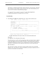
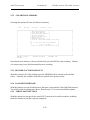
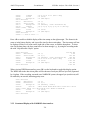
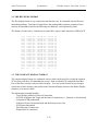
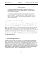
2.3.5 SEND TRACE
You can transfer and save a trace captured by the Ultra-2080 to a file on a host computer for later
processing or archival purposes. Two processes are available using a communication program to
transfer ASCII files; and using XMODEM. You may also transfer trace to the optional floppy
disk.
You will need a cable connecting the Ultra-2080 serial port to your external host computer to use
serial send or receive. Selecting the method and direction of trace transfer results in other
prompts and menus to lead you through the process.
Only the Raw Data format can be restored from a host computer file back into the Ultra-2080's
trace memory. The other save file formats are provided for human-readable archiving. A utility
will be available in a C-source and IBM PC executable format for converting from raw data to
human readable format. Contact the factory for more information.
2-7
ANCOT Corporation
User=s Manual
SCSI Bus Analyzer Ultra-2080: Section 2
SERIAL PORT
P At the host computer end, you will need a communications program capable of
transferring ASCII files and storing them using the host computer file system. Most
UNIX systems provide these programs as system utilities. Apple Macintosh systems and
MS-DOS systems will require an add-on program. BITCOM or PROCOMM are perhaps
the most popular of these programs for the PC.
The Ultra-2080 must be connected to the host computer using a straight through cable.
See Appendix A for the pinout. Make sure the connections are made and the host is
setup for the same baud and data format as for the Ultra-2080.
Select ASerial Port (ASCII)@ or ASerial Port (Xmodem)@ from the menu and you will be
given a choice of file formats to transfer. Selecting ASerial Port (ASCII)@ will display the
following menu. The XMODEM transfer uses only the raw trace data format.
File
Tracing
Utilities
Emulator
Help
••••••••••••••••••••••••••••••••••••••••••••••••••••••••••••••••••••••••••••••••
• Save Trace...
•
•
• Restore Trace...
•
•
• Save Setup...
•
•
• Restore Setup...
•
•
• Send Trace
>> ••••••••••••••••••••••••••
•
• Re••••••••••••••••••••••••• Send Trace (ASCII) •••••••••••••••••••••••••••
•
• Fi•
•
•
• Pr• Select file FORMAT:
•
•
• DO• Format (x) Raw ( ) Structured ( ) Binary ( ) Hex dump ( ) Compact •
•
••••• Trace range to send:
•
•
•
•
Start Addr
[00000000]
•
•
•
•
End Addr
[0000F0EF]
•
•
•
• Trace memory range: ( 00000000- 0000F0EF )
•
•
•
•
•
•
•
•
< OK > <Cancel>
•
•
•
••••••••••••••••••••••••••••••••••••••••••••••••••••••••••••••••••••••••
•
•
•
•
•
•
•
••••••••••••••••••••••••••••••••••••••••••••••••••••••••••••••••••••••••••••••••
TRACING: Stopped TRIGGER: Disabled
PRINTER: Off
The 'Raw Data' format is the only one that can be downloaded into the Ultra-2080 later.
See Appendix C for a description of the content. The other formats are text files which
are duplicates of the trace display formats, identical to that which appears on the screen of
the Ultra-2080. These formats may be useful for comparisons and post-processing of the
trace information, but cannot be reloaded into the Ultra-2080. Note that they are not
compressed, and files are much larger than the 'Raw Data' format. For this reason,
post-processing of 'NON-Raw Data' formats will typically take much longer.
After selecting the format, select the trace memory range to be saved, then confirm the
transfer by selecting <OK> to start communications. Most communications programs
can be set to echo received characters to the screen, so you can follow the transfer as it is
progressing.
2-8
ANCOT Corporation
User=s Manual
SCSI Bus Analyzer Ultra-2080: Section 2
The transfer is completed when the EOT character (04 Hex) is sent to the host. When the
EOT is finally received, disable reception at the host end. This will automatically close
and save the file with most communications packages.
See Appendix E for an example of using the PC and the PROCOMM PLUS
communication package for saving the trace on a PC host.
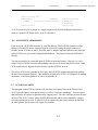
FLOPPY DISK
P
Select AFloppy Disk@ from the SEND FILE menu. Refer to the Serial Port menu.
File
Tracing
Utilities
Emulator
Help
••••••••••••••••••••••••••••••••••••••••••••••••••••••••••••••••••••••••••••••••
• Save Trace...
•
•
• Restore Trace...
•
•
• Save Setup...
•
•
• Restore Setup...
•
•
• Send Trace
>> ••••••••••••••••••••••••••
•
• Re••••••••••••••••••••••••• Send Trace (FLOPPY) ••••••••••••••••••••••••••
•
• Fi•
•
•
• Pr• Select file FORMAT:
•
•
• DO• Format (x) Raw ( ) Structured ( ) Binary ( ) Hex dump ( ) Compact •
•
••••• Trace range to send:
•
•
•
•
Start Addr
[00000000]
•
•
•
•
End Addr
[0000F0EF]
•
•
•
• Trace memory range: ( 00000000- 0000F0EF )
•
•
•
•
•
•
•
•
< OK > <Cancel>
•
•
•
••••••••••••••••••••••••••••••••••••••••••••••••••••••••••••••••••••••••
•
•
•
•
•
•
•
•
•
••••••••••••••••••••••••••••••••••••••••••••••••••••••••••••••••••••••••••••••••
TRACING: Stopped TRIGGER: Disabled
PRINTER: Off
The >Raw Data= format is the only one that can be later downloaded into the
Ultra-2080.
See Appendix C for a description of the content.
The other formats are text files which are duplicates of the trace display formats, identical
to that which appears on the screen of the Ultra-2080. These formats may be useful for
comparisons and post-processing of the trace information, but cannot be reloaded into the
Ultra-2080. Note that they are not compressed, and the files are much larger than the
>Raw Data= format.
After selecting the format, select the trace memory address range to be saved and the
filename to use. Once the file is written on the diskette, you may view the file on a PC if
you have not selected the raw data format.
2-9
ANCOT Corporation
User=s Manual
SCSI Bus Analyzer Ultra-2080: Section 2
2.3.6 RECEIVE TRACE
P SERIAL PORT
A trace saved to a file in 'Raw Data' format or XMODEM format can be loaded back into the
Ultra-2080 trace memory for more study. This function is analogous to saving the trace, as
described in Section 2.3.1, except that the direction of transfer is different.
Connect the Ultra-2080 to the host using a straight through cable. At the host computer end, start
the communications program and ready it to send either an ASCII or an XMODEM file.
Select ASerial Port (ASCII)@ or ASerial Port (XMODEM)@ from the RECEIVE FILE menu; the
following prompt will be displayed:
File
Tracing
Utilities
Emulator
Help
••••••••••••••••••••••••••••••••••••••••••••••••••••••••••••••••••••••••••••••••
• Save Trace...
•
•
• Restore Trace...
•
•
• Save Setup...
•
•
• Restore Setup...
•
•
• Send Trace
>>
•
•
• Receive Trace
>> ••••••••••••••••••••••••••
•
• File Management >> • Serial Port (ASCII)
•
•
• Print...
• Serial Port (XMODEM)
•
•
• DOS Shell
• Floppy disk
•
•
••••••••••••••••••••••••
•
•
•
••••••••••••••••••••••••••
•
•
•
•
•
•
•
•
•
•
•
•
•
•
•
•
•
•
•
••••••••••••••••••••••••••••••••••••••••••••••••••••••••••••••••••••••••••••••••
TRACING: Stopped TRIGGER: Disabled
PRINTER: Off
Select <OK> to confirm, then start the transfer from the host end.
2-10
ANCOT Corporation
User=s Manual
SCSI Bus Analyzer Ultra-2080: Section 2
Care has been taken to ignore any modem initialization characters your
communications package may send out before the actual file, but it is
impossible to allow for every possibility. If you repeatedly get the message
"Unrecognized format" when attempting to download, disconnect the
straight through cable until the next keystroke at the host-end will initiate.
Note again that only the Raw Data format file or the XMODEM format can be reloaded into the
Ultra-2080. Any other file format will result in the "Unrecognized format" message.
See Appendix E for an example of using the PC and the PROCOMM PLUS communication
package for restoring the trace from a PC host.
P FLOPPY DISK
A trace saved to the floppy in >Raw Data= format can be loaded back into the Ultra-2080 trace
memory for more study. This function is analogous to saving the trace, as described in Section
2.3.1 except that the direction of transfer is different.
Place the floppy diskette in the floppy disk drive and select AFloppy Disk@ from the RECEIVE
FILE menu; a file selection menu will be displayed.
The left half shows the files and the right half shows the directories and drives. The up and down
arrows move the cursor up and down in the window and the <TAB> <Shift TAB> keys move
the cursor between the two windows. Once the proper file has been selected, enter <Return>;
the file will be read from the floppy diskette to trace memory. If the format of the file is not
>Raw Data=, the file will not be loaded.
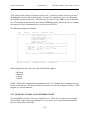
2.3.7 FILE MANAGEMENT
Under this heading you can save traces and setup parameters to the hard disk in the Ultra -2080.
There are also commands for manipulating files and directories on the disk. When you select
AFile Management@ from the File menu, the screen below will appear:
2-11
ANCOT Corporation
User=s Manual
SCSI Bus Analyzer Ultra-2080: Section 2
File
Tracing
Utilities
Emulator
••••••••••••••••••••••••••••••••••••••••••••••••••••••••••••••••••••••••••••••••
• Save Trace...
•
•
• Restore Trace...
•
•
• Save Setup...
•
•
• Restore Setup...
•
•
• Send Trace
>>
•
•
• Receive Trace
>>
•
•
• File Management >> •••••••••••••••••••••••••••••
•
• Print...
• Copy File...
•
•
• DOS Shell
• Delete File/Dir...
•
•
•••••••••••••••••••••••• File Attribute...
•
•
•
• Create Directory...
•
•
•
• Move (rename) File...
•
•
•
• Receive (Xmodem) File... •
•
•
• Format Drive...
•
•
•
•••••••••••••••••••••••••••••
•
•
•
•
•
•
•
•
•
•
•
••••••••••••••••••••••••••••••••••••••••••••••••••••••••••••••••••••••••••••••••
TRACING: Stopped TRIGGER: Disabled
PRINTER: Off
Copy a file.
<?=HELP>
Selecting one of the items will display the file selection menu with the appropriate heading.
Selecting AReceive (Xmodem) File@ will bring up the following menu:
File
Tracing
Utilities
Emulator
Help
••••••••••••••••••••••••••••••••••••••••••••••••••••••••••••••••••••••••••••••••
• Save Trace...
•
•
• Restore Trace...
•
•
• Save Setup...
•
•
• Restore Setup...
•
•
• Send Trace
>>
•
•
• Receive Trace
>>
•
•
• File Management >> •••••••••••••••••••••••••••••
•
• Print..••••••••••••Receive Xmodem File - Enter File Name•••••••••••••
•
• DOS She•
•
•
•••••••••• Path/filename C:\ancot.sys
•
•
•
•
•
•
•
•
< OK > <Cancel>
•
•
•
••••••••••••••••••••••••••••••••••••••••••••••••••••••••••••••
•
•
• Format Drive...
•
•
•
•••••••••••••••••••••••••••••
•
•
•
•
•
•
•
•
•
•
•
••••••••••••••••••••••••••••••••••••••••••••••••••••••••••••••••••••••••••••••••
TRACING: Stopped TRIGGER: Disabled
PRINTER: Off
This will allow you to download any file (using the >1K Xmodem= protocol) directly to the hard
disk on the Ultra2080.
2-12
ANCOT Corporation
User=s Manual
SCSI Bus Analyzer Ultra-2080: Section 2
This is most commonly used to download the file Aancot.sys@ to the root directory of the C drive
(C:\). This is a self extracting file which installs additional files needed by the Ultra2080.
2.3.8 PRINT
The APrint@ setting will turn parallel printing ON or OFF. The printing mode is indicated by a
message on the main menu. "Print: On" means that data being displayed on the screen is sent
also to the printer port. Note that only the trace data will be printed, not the menus.
You can print a hard copy of the trace information, just as it appears on the screen. A message
on the main menu near the bottom of the screen tells if printing is enabled. When printing is
active, each line of trace memory displayed on the screen will also be sent to the parallel printer
connector. Some displays use the IBM PC Extended Character Set for ASCII graphics. Be sure
that your printer has this font selected.
All trace display formats can be printed except the 'Command Profile'.
Printing can be enabled or disabled by pressing <Ctrl-P> on the keyboard anytime, from any
trace display menu. The <Enter> key toggles between enabled shown as 'X' in brackets, and
disabled shown by empty brackets.
When using a PC for remote control, use the <Alt-P> instead: the <Ctrl-P> is used by the PC
locally. However, when using the PROCOMM package on the PC, the printing function cannot
be used at all, because PROCOMM 'swallows' the <Alt-P>.
2.3.9 DOS SHELL
With the DOS shell you can enter commands at the AC:\>@ prompt to control the file system. The
list below shows the commands available. This Ahelp@ message is displayed when you first enter
the DOS shell. It may be repeated by typing A?@ or Ahelp@.
Command
------?,HELP
X,Q
Description
----------Help
Exit shell
Parameters
----------
2-13
ANCOT Corporation
CD
COPY
DEL
DIFF
DIR
FORMAT
MKDIR
MOVE
ATTRIB
WT
WS
RT
RS
User=s Manual
Change Directory
Copy file/dir
Delete file/dir
Compare files
Directory listing
Format Disk
Make Directory
Move file/dir
Change attributes
Write Trace
Write Setup
Read Trace
Read Setup
SCSI Bus Analyzer Ultra-2080: Section 2
PATH or CD to display CWD
FROMPATH TOPATH
PATH
PATH PATH
PATH
A: or C:
PATH
OLDNAME NEWNAME
PATH RDONLY|HIDDEN|SYSTEM|ARCHIVE|NORMAL
START END PATH
PATH
PATH
PATH
C:\SETUP\>
P CD Change Directory
"cd" by itself will display the current directory path. "cd" with a path will change to the
selected directory.
EXAMPLE:
cd traces cd \ -
This will change to the "traces" directory.
This will change to the root directory.
P COPY Copy file/dir
Acopy@ will copy one file to a new file. If the new file already exists, the copy will not take
place and a warning will be printed.
EXAMPLE:
copy trace1 trace2 - This will copy "trace1" to "trace2"
P DEL Delete file/dir
Delete a file or directory. A directory must be empty in order to delete it. The Adel@
command will not delete files with the RDONLY attribute set.
EXAMPLE:
del trace1 - delete the file Atrace1"
P DIFF Compare files
Compare two files to see if they are the same. This will not show differences, but will simply
compare them.
2-14
ANCOT Corporation
User=s Manual
SCSI Bus Analyzer Ultra-2080: Section 2
EXAMPLE:
diff trace1 trace2 - compare file Atrace1" with file Atrace2"
TRACE1) (TRACE2) Files are the same
P DIR Directory listing
This will display a list of files in the current directory. The display includes the time and date
of creation and the size of the file.
P FORMAT Format Disk
This will format either the hard disk or a floppy disk. An additional prompt will ask you to
confirm your intent to format the disk.
WARNING: Format will erase the contents of the disk.
Examples:
format c:
format a:
format the hard disk
format a floppy disk
P MKDIR Make Directory
Create a sub directory in the current directory.
EXAMPLE:
mkdir mytrace - creates the directory Amytrace@
P MOVE Move file/dir
This renames a file or directory.
EXAMPLE:
move trace1.trc mytrace.trc - moves (renames) Atrace1.trc@ to Amytrace.trc@
P ATTRIB Change attributes
This you can examine or change a file=s attributes. If no attributes are given, the file=s current
attributes are displayed. The attributes are RDONLY, HIDDEN, SYSTEM, ARCHIVE,
NORMAL. The DIRENT attribute is reserved for directories and cannot be changed. At the
present time, only the presence or absence of the RDONLY attribute is used.
2-15
ANCOT Corporation
User=s Manual
SCSI Bus Analyzer Ultra-2080: Section 2
EXAMPLES:
attrib mytrace - list the attributes of the file Amytrace@
Attributes: ARCHIVE
attrib mytrace rdonly - make the file Amytrace@ read only
attrib mytrace - list the attributes of the file Amytrace@
Attributes: ARDONLY|ARCHIVE
attrib mytrace normal - remove all file attributes
attrib mytrace - list the attributes of the file Amytrace@
Attributes: NORMAL FILE (No bits set)
P WT Write Trace
Write a trace or part of a trace to the disk. You must supply the start and end addresses of the
trace or you may use the default dash A-@ for either or both addresses. If the end address of
the trace is past the end of the current trace, the end of trace address will be used.
EXAMPLES:
wt 0 1ffff trace1 saves the entire trace to disk in file Atrace1".
wt - - trace1 saves the entire trace to disk (using default
addresses) in file Atrace1"
wt 1000 2000 trace1 - saves trace from address 1000 to 2000 to disk in file
Atrace1".
P WS Write Setup
This saves all the current setup parameters to the current directory on the disk. The
parameters include mode, trigger, utilities and emulator variables. For example, you could
setup certain trigger conditions and save them with the ws command (ws mytrig). You could
then read the settings back at a later time using the rs command (rs mytrig).
EXAMPLE:
ws setup1 - saves current setup to disk in the file Asetup1".
P RT Read Trace
Read a trace from the disk to trace memory. After reading the trace from disk to trace
memory, the trace may then be viewed in the normal manner.
EXAMPLE:
rt trace1 - read Atrace1" from the disk to trace memory.
2-16
ANCOT Corporation
P RS
User=s Manual
SCSI Bus Analyzer Ultra-2080: Section 2
Read Setup
Read a setup file from the disk and change setup parameters.
EXAMPLE:
rs setup1 - read Asetup1" from the disk and update all parameters.
P X, Q, Exit
Exit from the DOS shell.
2.4 TRACING
Select Tracing from the main menu to bring up the functions for tracing and for processing the
traces created. The following screen appears, with the functions listed in the pull-down menu.
File
Tracing
Utilities
Emulator
Help
••••••••••••••••••••••••••••••••••••••••••••••••••••••••••••••••••••••••••••••••
•
• Run
'R' •
•
•
• Stop
'S' •
•
•
• Display Trace
'D' •
•
•
• Pause
'P' •
•
•
• Find...
•
•
•
• Trace Mode Setup...
•
•
•
• Trigger Setup...
•
•
•
• Select Display Format... •
•
•
• Calculate Time Diff...
•
•
•
••••••••••••••••••••••••••••
•
•
•
•
•
•
•
•
•
•
•
•
•
•
•
•
•
•
•
•
•
••••••••••••••••••••••••••••••••••••••••••••••••••••••••••••••••••••••••••••••••
TRACING: Stopped
TRIGGER: Disabled
PRINTER: Off
Start tracing
<?=HELP>
Note that you can call up help from anywhere in the menu structure by entering A?@, or by
clicking on the symbols at the lower right corner of the screen above. See Subsection 2.6.
2.4.1
RUN
To put the Ultra-2080 into tracing mode:
press <Run> or <R> on the built-in keyboard
or press <F1> or <R> on the external keyboard
or click on ARun@ with mouse.
2-17
ANCOT Corporation
User=s Manual
SCSI Bus Analyzer Ultra-2080: Section 2
From that point on, all activity on the SCSI bus will be recorded, subject to the trigger
conditions in force.
See Section 2.2 for a discussion of tracing itself.
See Section 2.4.6 for a discussion of trace mode options.
See Section 5 for information on triggering.
2.4.2 STOP
Press <Stop> or <F2> to halt tracing. On the keyboard, <S> selects this function. With a
mouse, click on AStop@.
2.4.3
DISPLAY TRACE
This function shows you the activity which was recorded while tracing. See Section 3 for a
complete discussion of the display modes and how to interpret the various parts of the display.
From the external keyboard, the <D> or <F3> key is a selector for this function. With a mouse,
click on ADisplay Trace@.
This function may be selected while the trace is running. In this case it will automatically
perform the AStop@ function.
2.4.4
PAUSE
Press <Pause> to halt temporarily the recording of SCSI bus activity. Press <Run> to restart
recording. A message "Paused@ will appear. The 'seam' location will be marked in the trace
memory, and can later be found using the 'Find Event' command. On the keyboard, <P> or <F4>
will select this function. With a mouse, click on APause@.
2.4.5 FIND
This function searches trace memory for a particular pattern of control or data bits. Press
<Srch> or <F6> on the keyboard, or AFind@ from the ATracing@ menu on the display and activate
the AFind Trace Event@ menu.
See Section 4 for a complete discussion of the searching function.
2.4.6
TRACE MODE SETUP
2-18
ANCOT Corporation
User=s Manual
SCSI Bus Analyzer Ultra-2080: Section 2
Under this heading a new menu screen appears, with several selections applicable to the tracing
process, as listed below.
File
Tracing
Utilities
Emulator
Help
••••••••••••••••••••••••••••••••••••••••••••••••••••••••••••••••••••••••••••••••
•
• Run
'R' •
•
•
• Stop
'S' •
•
•
••••••••••••••••••••••••TRACE MODE SETUP••••••••••••••••••••••••••
•
•
•
•
•
•
•
NUMBER OF EDGES OF REQ/ACK TO CAPTURE
•
•
•
• REQ/ACK: (x) 4 edges
( ) 2 edges
( ) 1 edge
•
•
•
•
•
•
•
• [X] Capture phase changes
•
•
•
• [ ] ID Filtering [0000]
•
•
•
• [ ] Capture on Expansion Port bit 0
•
•
•
• [ ] Capture SCAM protocol
•
•
•
• [ ] Stop when trace memory is full.
•
•
•
•
•
•
•
•
DATA FILTER:
•
•
•
• Filter
(x) Save all data
( ) save first n bytes of data •
•
•
• Number of bytes to save [0
]
•
•
•
•
•
•
•
•
< OK > <Cancel>
•
•
•
••••••••••••••••••••••••••••••••••••••••••••••••••••••••••••••••••
•
•
•
••••••••••••••••••••••••••••••••••••••••••••••••••••••••••••••••••••••••••••••••
TRACING: Stopped TRIGGER: Disabled
PRINTER: Off
Continue
P
NUMBER OF EDGES OF REQ/ACK TO CAPTURE
With this function you can specify the number of edges of REQ and ACK to capture for
transferring a byte of data.
1 Edge - The Ultra-2080 will record only one event for each byte of data. The recording
will be made on the valid edge of REQ or ACK. These are determined by the I/O
signal. For data from the target to the initiator, REQ and I/O are asserted. For data
from the initiator to the target, ACK is asserted and I/O is de-asserted.
2 Edges - The Ultra-2080 will record two events for each byte of data. The recording will
be made on the leading edges of both REQ and ACK.
4 Edges - The Ultra-2080 will record four events for each byte of data. The recording
will be made on each edge, leading and trailing, of both REQ and ACK.
P CAPTURE PHASE CHANGES
This entry enables or disables the recording of transitions on the SCSI control lines :
MSG, C/D and I/O. When enabled, an 'X' character appears in the brackets, and any
transition on the information transfer phase-determining lines is recorded as a SCSI event.
When disabled, transitions on these lines do not cause an event to be recorded.
2-19
ANCOT Corporation
User=s Manual
SCSI Bus Analyzer Ultra-2080: Section 2
P ID FILTERING
This entry enables or disables the Filter mode of recording. When enabled, the tracing
circuits will record all transactions up to and including the selection phase. However,
unless the pattern of ID bits during the selection phase matches the user-defined pattern,
all other activity until the next Bus Free state will not be recorded. Note that it is the
exact pattern of bits during Selection phase that determines whether later events are
recorded. Therefore you can choose to observe only events between a particular pair of
devices.
The following example is provided to clarify this subject. Assume the bus being
monitored has Initiators as ID 6 and ID 7 and Targets as ID 0, ID 1 and ID 2. You might
think that you could capture all traffic to Target ID 1 from both Initiators. However, if
you try this by setting only bit number 1 in the pattern, that pattern will never be matched,
since both the Initiator's and Target's ID numbers are set during Selection phase. You
might also try setting bits 1, 6 and 7. That will not work either, since only two bits may
be set during selection phase. You can, however, capture all transactions between a pair
of ID numbers, for example ID 0 and ID 6. You could even capture only transactions
between ID 0 and ID 2 (although this situation would be questionable, since both of those
ID numbers belong to Targets).
When this function is enabled, you can set the bit pattern to match. Note that 16 bits are
provided in the pattern. This is to allow matching of SCSI WIDE Selection IDs. The
default pattern is for ID 7 (commonly used by Initiators) and ID 0 (commonly used by
Targets), and shows as the pattern [0081] in the menu.
P CAPTURE SELECTION ONLY
If 0000 is selected, this enables skipping of all events except transitions on the SCSI
BSY and SEL control lines. This mode is an extremely economical use of trace events
when you want is to see which IDs are being most utilized, or to determine the proportion
of idle to active time on the bus.
P CAPTURE ON EXPANSION PORT BIT 0
This function enables or disables recording of events when Exp(0) changes. When
enabled, any transition, up or down, on expansion connector bit 0 (DB-15 type connector,
pin-1) will cause recording of a snapshot of the SCSI bus, within 20 ns of the transition.
2-20
ANCOT Corporation
User=s Manual
SCSI Bus Analyzer Ultra-2080: Section 2
This mode is useful for relating the timing of signals internal in tested system to the
contents of the SCSI bus.
P CAPTURE SCAM PROTOCOL
With this mode you can record events during the auto-configuration process of the
SCSI-3 SCAM Protocol. In this mode, whenever both BSY and SEL signals are active,
transitions on D5, D6, or D7 (the SCAM Handshake lines) cause an event to be recorded.
Since transitions on the certain data lines cause recording (which in normal trace mode
would be ignored), more of the trace memory is used than in the normal trace mode.
Note: Use of this option requires that the ACapture Phase Changes@ option be enabled.
Refer to Appendix D and the SCSI-3 ANSI specification (document: SCSI-3 Parallel
Interface 'SPI', Annex B) for detailed descriptions of the SCAM protocol.
P STOP WHEN TRACE MEMORY IS FULL
With this mode selected, tracing will automatically stop when trace memory fills up, and
will not overwrite the beginning of the trace. This mode automatically sets the
appropriate trigger options.
2-21
ANCOT Corporation
User=s Manual
SCSI Bus Analyzer Ultra-2080: Section 2
P DATA FILTER
With this entry you can select the 'Skip Data' recording mode. The number in the
brackets shows how many data transfers will be recorded. If ASave first n bytes of data@
is enabled, using the left and right arrows, the number of bytes showing in the brackets
will be recorded. This number ranges from 1 to 255. In either case, the total number of
data transfers is counted and recorded in trace memory, and will appear in the structured
display. Skipping data does not inhibit the transfer of data across the SCSI bus. Only
recording is affected.
2.4.7
TRIGGER OPTIONS
See Section 5 for information on triggering.
2.4.8
SET DISPLAY FORMAT
With this function you can specify how the recorded activity is displayed. See Section 3 for a
complete discussion of the display modes.
2.4.9
TIME CALCULATION
With this function you can select two trace events by specifying their addresses, and calculate the
elapsed time between the two events. It uses the 20 nanoseconds resolution time stamp. This
function is also accessible from the trace display mode by pressing <Ctrl-T>.
From the main menu, select ATracing@, then ATime Calculation@ to access this utility. You can
also reach this function from any screen of trace memory display by pressing <^T> on the
keyboard.
You will be asked to provide two trace memory addresses. These may be entered in either order.
The utility then examines the time stamp for each event, and reports the time elapsed from the
earlier event to the later event. Note that elapsed time is modulo about 6 months, the timer
wrap-around period.
2-22
ANCOT Corporation
File
User=s Manual
Tracing
Utilities
Emulator
SCSI Bus Analyzer Ultra-2080: Section 2
Help
••••••••••••••••••••••••••••••••••••••••••••••••••••••••••••••••••••••••••••••••
•
• Run
'R' •
•
•
• Stop
'S' •
•
•
• Display Trace
'D' •
•
•
• Pause
'P' •
•
•
• Find...
•
•
•
• Trace •••••••••• Calculate Time Difference •••••••••••
•
•
• Trigge•
•
•
•
• Select•
Start Addr
[00000001]
•
•
•
• Calcul•
End Addr
[0000F0EE]
•
•
•
••••••••• Trace memory range: ( 00000000- 0000F0EF ) •
•
•
•
sec ms us ns
•
•
•
•
209 155 980
•
•
•
•
•
•
•
•
< OK >
•
•
•
••••••••••••••••••••••••••••••••••••••••••••••••
•
•
•
•
•
•
•
•
•
•
•
••••••••••••••••••••••••••••••••••••••••••••••••••••••••••••••••••••••••••••••••
TRACING: Stopped TRIGGER: Disabled
PRINTER: Off
The Astart@ and Aend@ addresses are automatically filled in as default values, and may be typed
over. The Astart@ address is always = 1, and the Aend@ address is the currently used trace memory
end. The time difference is in nanoseconds. In the example above, it is 209 milliseconds,
155 microseconds, and 980 nanoseconds.
2-23
ANCOT Corporation
User=s Manual
SCSI Bus Analyzer Ultra-2080: Section 2
2.5 UTILITIES
With this function you can select utilities not falling into any other category. From the main
menu, click on Utilities to bring up the screen below.
File
Tracing
Utilities
Emulator
Help
••••••••••••••••••••••••••••••••••••••••••••••••••••••••••••••••••••••••••••••••
•
• Show System Config.
•
•
•
• Clear Trace Memory
•
•
•
• Restore Factory Defaults
•
•
•
• Load New Firmware
•
•
•
• Serial Port Settings...
•
•
•
• Remote Control Using Ethernet Port... •
•
•
• Remote Control Using Serial port
•
•
•
• Time/Date Settings...
•
•
•
• Edit Colors...
•
•
•
• Screen Saver...
•
•
•
•••••••••••••••••••••••••••••••••••••••••
•
•
•
•
•
•
•
•
•
•
•
•
•
•
•
•
•
•
•
••••••••••••••••••••••••••••••••••••••••••••••••••••••••••••••••••••••••••••••••
TRACING: Stopped TRIGGER: Disabled
PRINTER: Off
Remote control using the Ethernet port and a browser.
<?=HELP>
│
Make your selections either by entering the highlighted letter directly, or by moving the highlight
bar over the chosen line, using the arrow keys, and pressing <Enter>. Individual functions are
explained below.
2.5.1 SHOW SYSTEM CONFIGURATION
Choosing this option will display on the screen all of the system options retained through the
power Off-On cycle, stored in non-volatile memory. Scroll through the screens with <PgUp> or
<PgDn>.
To print the configuration, enable printing before you choose this menu selection. If you are already displaying the information, press <Next> or <Prev>. If any of the options are printed, they
will all be printed (about 3 pages).
You can also see the default values for the system configuration. Press <Flip> to toggle between
defaults and current values.
2-24
ANCOT Corporation
User=s Manual
SCSI Bus Analyzer Ultra-2080: Section 2
2.5.2 CLEAR TRACE MEMORY
Choosing this option will clear all of the trace memory.
File
Tracing
Utilities
Emulator
Help
••••••••••••••••••••••••••••••••••••••••••••••••••••••••••••••••••••••••••••••••
•
• Show System Config.
•
•
•
• Clear Trace Memory
•
•
•
• Restore Factory Defaults •
•
•
• Load new firmware
•
•
•
• Serial Port Settings... •
•
•
• Remote control
•
•
•
• Time/Date Settings...
•
•
•
•••••••••• Clear Trace Memory •••••••••••
•
•
••
•
•
•
••
Do you wish clear trace memory?
•
•
•
••
•
•
•
•
< OK > <Cancel>
•
•
•
••••••••••••••••••••••••••••••••••••••••
•
•
•
•
•
•
•
•
•
•
•
•
•
•
•
••••••••••••••••••••••••••••••••••••••••••••••••••••••••••••••••••••••••••••••••
TRACING: Stopped
TRIGGER: Disabled
PRINTER: Off
Continue
Note that the trace memory is always cleared when you select RUN to start recording. Therfore
it is not necessary to use this function before new recording.
2.5.3 RESTORE FACTORY DEFAULTS
With this selection, all of the variables stored in EEPROM will be restored to their default
values. Similarly, the variables in SRAM are restored to the power-on state.
2.5.4 LOAD NEW FIRMWARE
With this function you can download a new firmware version into the Ultra-2080 flash memory.
You will be asked to confirm your choice. Read Section 7.6 for a more detailed description.
2.5.5 SERIAL PORT SETTINGS
With this option you can specify the exact RS-232 protocol to be used for transfers, including
baud rate, number of data bits, stop bits, and parity.
2-25
ANCOT Corporation
User=s Manual
SCSI Bus Analyzer Ultra-2080: Section 2
A list of the current settings will appear on the screen. Use the up or down arrow keys to move
the highlight to the item you wish to change. Use the left or right arrow keys to scroll through
the available options for that item. When all items are correct, select <OK> to record them and
exit. The settings are also stored in non-volatile EEPROM memory and will be used as a default
next time you do any communications, even after power OFF/ON.
The following settings are selectable:
File
Tracing
Utilities
Emulator
Help
••••••••••••••••••••••••••••••••••••••••••••••••••••••••••••••••••••••••••••••••
•
• Show System Config.
•
•
•
• Clear Trace Memory
•
•
•
• Restore Factory Defaults •
•
•
• Load new firmware
•
•
•
• Serial Port Settings... •
•
•
• Remote control
•
•
•
••••••••••••••• Serial Port Parameters •••••••••••••••••
•
•
•
•
•
•
• Baud rate
( ) 9600 ( ) 19200 ( ) 38400 (x) 115200 •
•
•
• Data bits
( ) 5 ( ) 6 ( ) 7 (x) 8
•
•
•
• Parity
(x) None ( ) Even ( ) Odd
•
•
•
• Stop bits
(x) 1 ( ) 2
•
•
•
•
•
•
•
•
< OK > <Cancel>
•
•
•
••••••••••••••••••••••••••••••••••••••••••••••••••••••••
•
•
•
•
•
•
•
•
•
•
•
••••••••••••••••••••••••••••••••••••••••••••••••••••••••••••••••••••••••••••••••
TRACING: Stopped
TRIGGER: Disabled
PRINTER: Off
When shipped from the factory, the Ultra-2080 default setting is:
9600 baud
8 data bits
no parity
1 stop bit
NOTE: While some communications programs can use 115.2 Kbaud, some computers may not
be able to use this rate. This may result in lost characters or cause the computer to "hang". If this
happens, use a lower baud rate.
2.5.6 REMOTE CONTROL USING ETHERNET PORT
The Ultra2080 has a built in web server and FTP server. The web server allows you to control
the Ultra2080 with a web browser and the FTP server allows you to upload and download files
between a host and the Ultra2080.
2-26
ANCOT Corporation
User=s Manual
SCSI Bus Analyzer Ultra-2080: Section 2
When using the web server, remember that more than one person may be connected to the unit at
any one time. This feature can be an advantage if used properly. For example, it allows a group
of engineers to study the same trace and discuss the same situation. It also allows viewing a trace
in more than one format, if, for example you use two browser windows and open the same trace
but display it in different formats (e.g. one in structured, the other in binary format). This
flexibility is an advantage however, care must be taken that users do not interfere. It is best if
only one user controls the unit while the other users limit themselves to viewing.
Use functions in your browser to save copies of the trace to be used for later viewing or editing.
Use the editing features in your browser if only a part of the trace is to be saved.
Select the ARemote Control Using Ethernet Port@ from the Utilities menu, and the following submenu will be displayed:
File
Tracing
Utilities
Emulator
Help
••••••••••••••••••••••••••••••••••••••••••••••••••••••••••••••••••••••••••••••••
•
• Show System Config.
•
•
•
•••••••••••••••••••••••ETHERNET SETUP•••••••••••••••••••••••••
•
•
•
•
•
•
• Web server is STOPPED
•
•
•
• FTP server is STOPPED
•
•
•
•
•
•
•
• Web Server: ( ) Start
( ) Stop
(x) No change
•
•
•
• FTP Server: ( ) Start
( ) Stop
(x) No change
•
•
•
•
•
•
•
•
My IP Address 192.168.0.0
•
•
•
•
My Mask 255.255.255.0
•
•
•
• My Gateway Address 192.168.0.254
•
•
•
•
My Network Name Ancot Ultra2080
•
•
•
•
•
•
•
• [ ] Start Web server on power up.
•
•
•
• [ ] Start FTP server on power up.
•
•
•
•
•
•
•
•
< OK > <Cancel>
•
•
•
••••••••••••••••••••••••••••••••••••••••••••••••••••••••••••••
•
•
•
••••••••••••••••••••••••••••••••••••••••••••••••••••••••••••••••••••••••••••••••
TRACING: Stopped TRIGGER: Disabled
PRINTER: Off
This menu allows you to setup the Ethernet port and the servers in your Ultra2080. It also shows
the current status of the web server and the FTP server (either STOPPED or RUNNING). You
may start or stop one or both servers by checking the appropriate boxes. You must also set a
valid IP address (My IP Address, Mask, and Gateway) for this particular Ultra2080. Consult
your system administrator in order to obtain a valid IP address. In addition, you may configure
the Ultra2080 to automatically start up one or both of the servers after power on. The default is
NOT to start the servers.
When the Ultra2080 web server responds to a request, a packet is sent to the originating
(destination) IP address. If both the Ultra2080 and the destination address are on the same
network, the packet is sent to the destination IP address. If they are not on the same network, the
packet is sent to the IP address of a gateway. The gateway will forward the packet. The mask is
2-27
ANCOT Corporation
User=s Manual
SCSI Bus Analyzer Ultra-2080: Section 2
used to determine if the destination IP address is on the same network. A value of 255 means to
match the corresponding value exactly, and a value of 0 means to ignore the value. For a value
of 255.255.255.0, this means that the first three numbers must match exactly. For this mask,
this gives a range of 256 IP addresses.
IP Address The IP address of the Ultra2080 on your local network. See your system
administrator to obtain a valid IP address.
Mask The mask for your IP address. A value of 255 is an exact match. A value of 0 is ignored.
Gateway Address The IP address to send the packet to if the destination is not on your local
network. The gateway will forward the packet.
Network Name This is a local name which you can assign to the Ultra2080. If you hard code a
network name, set this tring to match.
The factory default IP address is 192.168.0.0. This is an Ancot assigned private address which
should only be used in private settings, in LAN within an enterprise, where it would be unique.
This address may run into conflict situations in settings where more enterprises are involved.
After entering the IP address and checking the desired selection boxes, press <OK> (for Quit) to
apply the settings and exit. Pressing <Cancel> will not change anything and will return you to
the main menu. Physical connection of the Ultra2080 to your network by is by cable connected
to the RJ45 connector on the front panel. The Ethernet hardware will automatically detect the
proper speed of your network (either 10 or 100 Mbit Ethernet).
If you exit this menu with the Web Server in RUNNING mode, and if the Ultra2080 is connected
to the LAN, then you can access it remotely using (almost) any of the popular browsers. Use
your IP address as the web page name - example: Ahttp//www.192.168.0.0".
When System Defaults are restored, both servers will be stopped (now and after power up), and
Ancot factory default IP address will be set.
2-28
ANCOT Corporation
User=s Manual
SCSI Bus Analyzer Ultra-2080: Section 2
2.5.7 REMOTE CONTROL USING SERIAL PORT
There are situations when a SCSI system at a remote location needs testing or troubleshooting. It
is possible to connect the Ultra-2080 Analyzer to the SCSI bus to be tested, and connect the
controlling terminal over a modem, or via a straight through cable.
The operator at Site A, the test site, connects the Ultra-2080 to the SCSI bus system as usual.
the test site (we will call this site-A, and the receiving end site-B) simply connects. The
Ultra-2080 Serial-1 Port is then connected to the modem port; the terminal, or host computer, is
connected to the other end of the telephone line, Site B. If Site-A and Site-B are close together,
a straight through cable can be used instead. See Appendix A for the pinout.
Site-A setup: connect the Ultra-2080 to the SCSI bus under test, and enable the remote control
by selecting the UTILITIES menu, and ARemote Control@. A message will appear on the screen
asking for confirmation. Press <Y> to confirm this, and the message
THIS UNIT IS UNDER REMOTE CONTROL - DO NOT DISTURB
appears on the screen. At this point the keyboard, if connected to J4, is disabled. The Ultra2080 can be restarted, to restore control from site-A, by pressing the SYSTEM RESET push
button, or by turning the power OFF and ON.
Site-B operation: log onto the remote terminal or host computer, and start the communications
utility program (BITCOM, PROCOMM or similar, using the VT-100 setting). The screen should
clear, and the UTILITY menu from the Ultra-2080 (from site-A by modem) should display on
your screen. At this point, the keyboard on your remote terminal should act as if connected
directly to the Ultra-2080; all functions on the Ultra-2080 should be operational.
When finished with the session, select the Utilities menu from your remote terminal, select item
6 to disable remote control, and confirm the selection by pressing <Y>. Control will return to the
Ultra-2080 local screen and keyboard. Remote control can also be disabled by pressing the
SYSTEM RESET switch on the Ultra-2080 front panel, or by cycling power to the Ultra-2080.
The terminal used for remote control should support the ANSI escape sequences for clearing,
moving the cursor, and for inverse video. See Appendix B for definitions of the sequences used.
2-29
ANCOT Corporation
2.5.8
User=s Manual
SCSI Bus Analyzer Ultra-2080: Section 2
TIME/DATE SETTINGS
With this function you can change the date and time on the Ultra-2080. These entries are used by
the disk software to assign a creation date and time for any saved traces or setups. The display
shown below is used to change the date and time:
File
Tracing
Utilities
Emulator
Help
••••••••••••••••••••••••••••••••••••••••••••••••••••••••••••••••••••••••••••••••
•
• Show System Config.
•
•
•
• Clear Trace Memory
•
•
•
• Restore Factory Defaults •
•
•
• Load New Firmware
•
•
•
• Serial Port Settings... •
•
•
• Remote Control
•
•
•
••••••••••••••••••••••••••SET DATE AND TIME•••••••••••••••••••••••••••
•
•
•
•
•
•
• Time
04:50:03
•
•
•
• Date
11/12/98
•
•
•
• Weekday
( ) Sun ( ) Mon ( ) Tue ( ) Wed (x) Thu ( ) Fri ( ) Sat •
•
•
•
•
•
•
•
< OK > <Cancel>
•
•
•
••••••••••••••••••••••••••••••••••••••••••••••••••••••••••••••••••••••
•
•
•
•
•
•
•
•
•
•
•
•
•
••••••••••••••••••••••••••••••••••••••••••••••••••••••••••••••••••••••••••••••••
TRACING: Stopped TRIGGER: Disabled
PRINTER: Off
(HH:MM:SS)
Select either ATime@ or ADate@ to edit the field. Select AWeekday@ to set the proper day of the
week.
2.5.9
THE SCREEN SAVER
LCD displays like the one in the Ultra-2080 can have their life extended by using a screen saver.
If a significant time passes with no keyboard or display activity, the screen will blank. To bring
it back, press any key except Ctrl, Alt, and Shift.
You can turn off the screen saver feature from the Utility menu. Choose AEnable Screen Saver@
to toggle between enabled or disabled.
2-30
ANCOT Corporation
User=s Manual
SCSI Bus Analyzer Ultra-2080: Section 2
File
Tracing
Utilities
Emulator
Help
••••••••••••••••••••••••••••••••••••••••••••••••••••••••••••••••••••••••••••••••
•
• Show System Config.
•
•
•
• Clear Trace Memory
•
•
•
• Restore Factory Defaults
•
•
•
• Load New Firmware
•
•
•
• Serial Port Settings...
•
•
•
• Remote Control Using Ethernet Port... •
•
•
• Remote Control Using Serial port
•
•
•
•••••••••••••••••••Screen Saver•••••••••••••••••••••
•
•
•
•
•
•
• [X] Enable Screen saver
•
•
•
• Wait [05] minutes before turning screen off.
•
•
•
•
•
•
•
•
< OK > <Cancel>
•
•
•
••••••••••••••••••••••••••••••••••••••••••••••••••••
•
•
•
•
•
•
•
•
•
•
•
•
•
••••••••••••••••••••••••••••••••••••••••••••••••••••••••••••••••••••••••••••••••
TRACING: Stopped TRIGGER: Disabled
PRINTER: Off
The default timeout before the screen saver takes effect is 5 minutes. To change this value, enter
a number from 1 to 99 (minutes) in the brackets.
2.6 SCSI INITIATOR EMULATOR
Choosing this function will allow you to enter the SCSI Initiator Emulator menu. See Section 6
for a detailed description of all the SCSI Initiator Emulator functions. Note that the Emulator
function is optional and the AEmulator@ label will be displayed only in systems with the SCSI
Emulator hardware installed.
2-31
ANCOT Corporation
User=s Manual
SCSI Bus Analyzer Ultra-2080: Section 2
2.7 HELP
From the main menu, click on Help to bring up the screen below.
File
Tracing
Utilities
Emulator
Help
••••••••••••••••••••••••••••••••••••••••••••••••••••••••••••••••••••••••••••••••
•
• Keys
•
•
•
• Triggering
•
•
•
• Filtering
•
•
•
• Tracing
•
•
•
• About
•
•
•
••••••••••••••••••••
•
•
•
•
•
•
•
•
•
•
•
•
•
•
•
•
•
•
•
•
•
•
•
•
•
•
•
•
•
••••••••••••••••••••••••••••••••••••••••••••••••••••••••••••••••••••••••••••••••
TRACING: Stopped
TRIGGER: Disabled
PRINTER: Off
Key descriptions
<?=HELP>
Only the >About= selection is implement with the first release. More to be added later
2-32
ANCOT Corporation
User=s Manual
2-33
SCSI Bus Analyzer Ultra-2080: Section 2
ANCOT Corporation
User=s Manual
SECTION
SCSI Bus Analyzer Ultra-2080: Section 3
3
DISPLAYING THE TRACE MEMORY
3.1 INTRODUCTION
The Ultra-2080 has several display formats for the data captured by tracing. Each format has its
own characteristics and special capabilities to let you view the events recorded.
When you select Tracing from the main menu, then Display Trace, or >D==, or <Disp>, or <F3>,
the following menu will be displayed:
File
Tracing
Utilities
Emulator
Help
••••••••••••••••••••••••••••••••••••••••••••••••••••••••••••••••••••••••••••••••
•
• Run
'R' •
•
•
• Stop
'S' •
•
•
• Displa•••••••••••••••• Display Trace •••••••••••••••••
•
•
• Pause •
•
•
•
• Find..• Display format:
•
•
•
• Trace • [X] Structured
•
•
•
• Trigge• [ ] Binary
•
•
•
• Select• [ ] Compact
•
•
•
• Calcul• [ ] HexDump
•
•
•
••••••••• [ ] Profile
•
•
•
•
•
•
•
• [ ] Display a Range (Use start AND end)
•
•
•
•
•
•
•
• Trace memory range: ( 00000000- 0001ffff)
•
•
•
•
Start Addr
[00000000]
•
•
•
•
End Addr
[0001FFFF]
•
•
•
•
•
•
•
•
< OK > <Cancel>
•
•
•
••••••••••••••••••••••••••••••••••••••••••••••••
•
•
•
••••••••••••••••••••••••••••••••••••••••••••••••••••••••••••••••••••••••••••••••
TRACING: Stopped TRIGGER: Disabled
PRINTER: Off
Structured display format
This screen will allow you to select the display format and a starting address. If you select
ADisplay a Range ...@, the trace will display continuously from the start address to the end.
Displaying within a range longer than one screen length would usually be selected when also
generating hard copy on a printer. Use <^P> on the keyboard to toggle the printer ON and OFF.
When displaying a range longer than one screenful, press any key on the keyboard to pause the
display. A prompt at the bottom of the screen will tell you how to stop displaying (AQ@ or
A<Esc>@), or continue displaying (any key). After all selections have been made, select <OK>
with the arrow keys or with the mouse, or press <Ctrl-Home> followed by <Enter>.
The following table describes the keys you can use while displaying a trace.
3-1
ANCOT Corporation
User=s Manual
SCSI Bus Analyzer Ultra-2080: Section 3
The following keys are active in the trace display mode: (letters are case insensitive)
Moving around in a trace:
Key
Meaning
--------<down arrow>
Scroll down one line
<up arrow>
Scroll up one line
<PgDn>,<Space>,+
Scroll down one screen
<PgUp>,Scroll up one screen
<Home>
Display one screen starting at the beginning of the
trace
<End>
Display one screen ending with the end of the trace
A
Display one screen starting at a given address
Changing to another trace format:
Key
Meaning
--------F,F5,<Flip>
Flip between structured and binary display or flip
from
any other display format to structured format
B
Display trace in binary format.
C
Display trace in compact format.
D
Display trace in hex dump format.
P
Display trace in command profile format.
S
Display trace in structured format.
^d
Display trace in diagnostic format.
Changing the appearance of a trace:
Key
Meaning
--------W
Flip between wide (16-bit) and narrow (8-bit) data
display. When displaying wide data, the low byte
appears
first, separated by a hyphen from the high byte. The
separator character may be an asterick (*) if a parity
error occurs or a plus-sign (+) if the ATN line is
active.
H
Structured display only.
Flip between ASCII or hexadecimal display of the data
bytes. Unprintable characters appear as periods.
E
Binary format - flip the time display between total
elapsed time since the start of tracing or
differential time between successive events.
Structured format - Turns on and off the displaying of
differential time on the right edge of the screen if
there is sufficient room.
<right arrow>,
Flip between displaying coarse and fine time for time
<left arrow>
displays which exceed approximately 83 seconds. Times
exceeding 83 seconds are indicated with a "<" or ">"
to the left of a time.
Misc.:
Key
Meaning
--------Q,ESC
Quit and return to previous menu
R,F1,<Run>
Start recording a new trace and return to the main
menu.
^t
Compute the time difference between two trace events.
3-2
ANCOT Corporation
^f,F6,<Find>
^k,Shft<find next>
^l,<find next>
^p
User=s Manual
SCSI Bus Analyzer Ultra-2080: Section 3
Open the find menu to search the trace for selected
events.
Find the previous occurence of an event.
Find the next occurence of an event.
Toggle the printer ON and OFF.
3-3
ANCOT Corporation
User=s Manual
SCSI Bus Analyzer Ultra-2080: Section 3
3.2 THE STRUCTURED DISPLAY FORMAT
This format is the easiest to read and interpret. Each line of display starts with the trace memory
address of the first event of the line. Each SCSI phase is labeled with its name. In addition, the
first byte of the Command Descriptor Block (CDB) is interpreted, as are each Message byte and
Status byte. Phases are indented as with program structure. The Reset condition and Bus Free
phases are aligned with the left edge of the display after the address. Arbitration, Selection and
Reselection phases are indented one tab stop, 3 spaces. Command, Status, Message-In and
Message-Out phases are indented a further tab stop, 6 spaces. Data-In, Data-Out and the two
Reserved phases are indented another tab stop, 9 spaces.
The actual data transferred, as well as the ID numbers during Arbitration, Selection and
Reselection, are shown in Hex, following a slash. If a parity error occurs at any time, except in
the arbitration phase, an asterisk will follow directly after the offending byte. If no parity error
occurred, but the SCSI ATN line is active, that is shown as a plus-sign following the byte.
Data count, i.e., the number of transfers during the Data-In or Data-Out phase, is shown in Hex
format and in parentheses just after the trace memory address for the last line of the data phase.
NOTE:
There are situations when the tested system hangs during the data phase, and you need to find
out how many data bytes were actually transferred. Normally, when the system hangs, you
press <Stop> or <S> to stop the tracing, then <Disp> or <D> to display the trace. You will
not see the data count (in parentheses) at the end of the last (hung) data phase on the
structured display. This is because the data count is recorded in the trace memory when the
Bus Free phase is entered. The Ultra-2080 stores data count in the data byte memory of the
Bus Free event. This recording is all done by hardware because of the recording speed
requirement. If you need to see the data count, press the SCSI RESET pushbutton to reset the
Target before you press <Stop>; this will result in Bus Free phase, and subsequent recording
of the data count in the trace memory.
To avoid clutter, multi-byte messages have the phase label only on the first byte. Multi-line data
phases are also labeled only on the first line.
When enabled, the duration of each phase is displayed on the last line of that phase, if space is
available on the line. Press <E> to toggle between timing display enabled or disabled.
Several samples of Structured displays are shown below, with the various recording and display
modes.
3-4
ANCOT Corporation
User=s Manual
SCSI Bus Analyzer Ultra-2080: Section 3
3.2.1 Structured Display with NARROW or WIDE data transfers
The example display on the next page shows the data in ASCII format. The recording captured
all data. This recording was made with ACapture 1 edge of REQ/ACK enabled@. Note that in
line 4 the IDs of the SCSI devices involved are shown both as the bits set on the SCSI bus, and as
the decimal equivalent ID numbers of the two devices. Also note that during the first
Message-Out phase, the Initiator held ATN active, as shown by the (+) following each message
byte. This trace shows a typical boot sequence for a host adapter card at ID 7 finding out about
the Target device at ID 0.
00000:
00001:
00004:
00007:
00008:
00009:
0000A:
0000B:
0000C:
0000D:
0000E:
0000F:
00010:
00011:
00012:
00018:
00028:
00038:
0003C:
0003D:
0003E:
0003F:
00042:
00045:
00046:
00047:
00048:
00049:
0004A:
0004B:
0004C:
0004D:
0004E:
0004F:
00050:
00056:
0005E:
0005F:
00060:
00061:
00064:
00067:
---- Start Trace ---Arbitration
/80 (7)
Select w/ATN
/81 (0,7)
Message-Out
/C0+(Identify : LUN 0 Disconnect OK)
Message-Out
/01+(Ext Msg)
03+(Length)
01+(SDTR)
28+(Period 160 nsec)
08 (Offset 8 bytes)
Message-In
/01(Ext Msg)
03 (Length)
01 (SDTR)
32 (Period 200 nsec)
08 (Offset 8 bytes)
Command
/12 00 00 00 30 00 (Inquiry)
Data-In
/ . . . . . . . . A N C O T
D S C - 3 0 2 / J
(0024)
3 . 4 0
Status
/00 (Good)
Message-In
/00 (Cmd Cmplt)
Bus Free
Arbitration
/80 (7)
Select w/ATN
/81 (0,7)
Message-Out
/C0+(Identify : LUN 0 Disconnect OK)
Message-Out
/01+(Ext Msg)
03+(Length)
01+(SDTR)
28+(Period 160 nsec)
08 (Offset 8 bytes)
Message-In
/01 (Ext Msg)
03 (Length)
01 (SDTR)
32 (Period 200 nsec)
08 (Offset 8 bytes)
Command
/03 00 00 00 10 00 (Req Sense)
(0008)
Data-In
/ p . . . . . . .
Status
/00 (Good)
Message-In
/00 (Cmd Cmplt)
Bus Free
Arbitration
/80 (7)
Select w/ATN
/81 (0,7)
Message-Out
/C0 (Identify : LUN 0 Disconnect OK)
3-5
ANCOT Corporation
00068:
0006E:
0006F:
00070:
00071:
00074:
00077:
00078:
00082:
0008A:
0008B:
0008C:
0008D:
User=s Manual
Command
/00
Status
/00
Message-In
/00
Bus Free
Arbitration
/80
Select w/ATN
/81
Message-Out
/C0
Command
/25
(0008)
Data-In
/ .
Status
/00
Message-In
/00
Bus Free
---- End of Trace ----
SCSI Bus Analyzer Ultra-2080: Section 3
00 00 00 00 00 (Test U Rdy)
(Good)
(Cmd Cmplt)
(7)
(0,7)
(Identify : LUN 0 Disconnect OK)
00 00 00 00 00 00 00 00 00 (Rd Cap)
. . . . . . .
(Good)
(Cmd Cmplt)
Press <E> to enable or disable display of the time stamp on the right margin. The format is the
same as in the binary display, and it specifies time for that certain phase. The time stamp will not
be displayed if there is no room on the right side of the screen, as with the data phase. To show
time for the data phase, the byte count has to be short enough, e.g., by using the recording mode
the with "skip data after 8 bytes" option.
00060: Bus Free
00061:
Arbitration
00064:
Select w/ATN
00067:
Message-Out
00068:
Command
0006E:
Status
0006F:
Message-In
00070: Bus Free
/80
/81
/C0
/00
/00
/00
(7)
(0,7)
(Identify : LUN 0 Disconnect OK)
00 00 00 00 00 (Test U Rdy)
(Good)
(Cmd Cmplt)
354 934
3
833
589
2 061
1 061
663
3 415
680
560
600
920
040
720
920
120
When viewing WIDE data transfers, press <W> on the keyboard to toggle this display option.
The WIDE data in the data-in/out phase will be shown as two bytes (the low byte first) separated
by a hyphen. If the recording was made on a NARROW system, the upper byte (not driven) will
be marked by an asterisk, indicating parity error.
00187: Bus Free
00188:
Arbitration
/01 (0)
0018A:
Reselection
/81 (0,7)
0018D:
Message-In
/80 (Identify : LUN 0)
00191:D
Data-In
/DE-E7 D4-D8 FD-FF DE-80 FD-D7 33-AD CF-77 D8-39
001D1: (0200) BA-6F 76-77 FE-7D B9-1E C3-F7 EF-E6 D7-8A EA-EC
0020F:
Status
/00 (Good)
00213:
Message-In
/00 (Cmd Cmplt)
00217: Bus Free
3.2.2 Structured Display with NARROW data transfers
3-6
ANCOT Corporation
User=s Manual
SCSI Bus Analyzer Ultra-2080: Section 3
The following display is shown with data in Hex. Recording was done in Skip-Data (32
transfers) mode, with 'capture 4 edges REQ/ACK' mode turned ON. Note the byte count (in
parentheses, in Hex format) on the last line of the data phase for each transfer.
00000:
00001:
00004:
00008:
0000C:
00023:
00027:
00028:
0002A:
0002D:
00031:
00071:
000AF:
000B3:
000B7:
000B8:
000BB:
000BF:
000C3:
000DA:
0011A:
00158:
0015C:
00160:
00161:
00164:
00169:
0016C:
00183:
00187:
00188:
0018A:
0018D:
00191:
001D1:
0020F:
00213:
---- Start Trace ---Arbitration
/80
Select w/ATN /81
Message-Out
/C0
Command
/08
Message-In
/04
Bus Free
Arbitration
/01
Reselection
/81
Message-In
/80
Data-In
/00
(0200)
00
Status
/00
Message-In
/00
Bus Free
Arbitration
/80
Select w/ATN
/81
Message-Out
/C0
Command
/08
Data-In
/FF
(0200)
FF
Status
/00
Message-In
/00
Bus Free
Arbitration
/80
Select w/ATN
/81
Message-Out
/C0
Command
/08
Message-In
/04
Bus Free
Arbitration
/01
Reselection
/81
Message-In
/80
Data-In
/DE
(4400)
BA
Status
/00
Message-In
/00
(7)
(0,7)
(Identify : LUN 0 Disconnect OK)
00 00 00 01 00 (Read/Rcv)
(Disconnect)
(0)
(0,7)
(Identify : LUN 0)
00 00 00 00 00 00 00 00 00 00 00 00 00 00 00
00 00 00 00 00 00 00 00 00 00 00 00 00 00 00
(Good)
(Cmd Cmplt)
(7)
(0,7)
(Identify :
00 00 22 01
FF FF F7 FF
FF FF FF FF
(Good)
(Cmd Cmplt)
LUN 0 Disconnect OK)
00 (Read/Rcv)
FF 7F 15 FE FF FF FF FF FF F7 6F
FF FF FF BB FF FF FF FF FF FF 9F
(7)
(0,7)
(Identify : LUN 0 Disconnect OK)
00 00 5C 22 00 (Read/Rcv)
(Disconnect)
(0)
(0,7)
(Identify : LUN 0)
E7 D4 D8 FD FF DE 80 FD D7 33 AD CF 77 D8 39
6F 76 77 FE 7D B9 1E C3 F7 EF E6 D7 8A EA EC
(Good)
(Cmd Cmplt)
00217: Bus Free
00218: ---- End of Trace ----
3.2.3 Structured Display of SCAM Protocol
3-7
ANCOT Corporation
User=s Manual
SCSI Bus Analyzer Ultra-2080: Section 3
In the structured display, you will see the SCAM Protocol in plain English. A sample is shown
below. During the Isolation phase, it is assumed that the identification string, after the 'type' code
bytes, is printable ASCII, and is displayed that way. For the 'type' code, and for any
non-printable character, the value is displayed in Hexadecimal between angle brackets <xx>.
Function codes are displayed both in Hexadecimal and in English. The Isolation phase is labeled
as either 'Terminated' or 'Complete'. Command codes are given in English. In all cases, if an
illegal handshake occurs, it is labeled as such. One example is at the end of the SCAM process,
when the Master releases C/D.
00000:
00001:
00002:
00002:
00004:
00005:
0000B:
00011:
00017:
000F8:
000FE:
00102:
00103:
---- Start Trace ---RESET Start
RESET End
Bus Free
Arbitration
/(no ID)
SCAM Selection
SCAM Function : 1F Synch Pattern
SCAM Function : 00 Assign ID
Name : <12><00> ANCOT
SCAM Test 00001 (Complete)
Assign ID 00
SCAM Function : Invalid handshake
Bus Free
---- End of Trace ----
Note that in order to analyze the SCAM Protocol, the trace needs to be recorded in the 'Capture
SCAM Protocol' mode first.
3.3 THE BINARY DISPLAY FORMAT
If the Structured display format is compared to a computer program written in a high-level
language, the Binary display format is like the same program written in assembly language. In
the Binary format, each event captured gets one line of display. In this display format, you can
see the exact state of each SCSI control line at the time of the event's capture, plus the state of the
SCSI data lines and the Ancot expansion lines. Furthermore, the timing of the activity is shown,
accurate to the 4ns resolution of the Ultra-2080. There are several options in how the
information is presented in the Binary format.
The control lines are shown in logic analyzer style, as a rectangular waveform traveling down the
page. An active signal is shown as a thin line on the right side of the area dedicated to that
control line. Inactive signals show as thick lines on the left side of their respective areas.
Data can be shown as wide or narrow. If the wide data format is chosen, the low byte is shown
first, separated from the high byte by a hyphen (-). If a parity error occurred, that is shown by
3-8
ANCOT Corporation
User=s Manual
SCSI Bus Analyzer Ultra-2080: Section 3
an asterisk (*) following the offending byte. The asterisk (*) may replace the hyphen (-)
separating the two bytes. The bytes are shown in hexadecimal first, followed by their ASCII
equivalent in parentheses.
Each line of display also shows the state of the three signals received through the expansion connector J2 (DB-15) marked as 'Exp' in the examples below. E2 is the most significant bit, shown
on the left of the triad. It is followed by E1 and then E0.
Time stamp information comes in either of two formats also. In the elapsed format, the total
elapsed time since the start of the recording (modulo about 200 days) is shown in the time
column. In the differential format, the time differential between the two events is shown in the
time column. All times are expressed as decimal nanoseconds, with a space between each group
of three digits. As an example, the "3 123 456 789" represents 3sec 123ms 456Fs 789ns.
If a less-than symbol ("<") appears to the left of the time stamp, the time exceeded approximately
83 seconds. To see the larger numbers of the time stamp, press the left or right arrow keys. The
following illustration shows a time stamp with a large time.
<51 371 901 220 or > 0h 01m 51s
s ms Fs ns
The total time shown by this time stamp is 0 hours, 1 minute, 51 seconds, 371 milliseconds, 901
microseconds, and 220 nanoseconds.
Each line of display shows whether the data byte on that line is valid. If it is valid, then the
address on the left is followed by a right angle bracket (>). If not, the address is followed by a
colon (:). The various display options are shown in the following sample displays.
The display example on the next two pages shows the logic analyzer style of control signals, with
8-bit data and differential time display. This trace also shows the 'capture 4 edges REQ/ACK'
and 'capture-all-data' modes of recording. Note that the data word, at the Bus Free event after the
command, holds the data count (0008 bytes) in the data-in phase of this command. Just to the
right of the Exp column, during the data phase only, the current REQ/ACK offset is shown as a
2-digit hexadecimal number. This number is valid only in 4-edge mode. The number is
generated from the recording of the REQ and ACK signals in the data phase; if the recording
mode does not include 4-edge capture, the offset is not shown.
3-9
ANCOT Corporation
User=s Manual
SCSI Bus Analyzer Ultra-2080: Section 3
Addr: BSY SEL ATN RST MSG I/O C/D REQ ACK Ph Data/PE
Exp
00000: ---- Start Trace ---00001:
• •_ •
•
•
•
•
•
•
Arb 80
(.) 000
00002:
•
• •_ •
•
•
•
•
•
80
(.) 000
00003> _•
•
• •
•
•
•
•
•
81
(.) 000
00004: •_
•
• •
•
•
•
•
•
Sel 81
(.) 000
00005:
• _•
• •
•
•
•
•
•
81
(.) 000
00006:
• •
• •
•_ •
•_ •_ •
00* (.) 000
00007:
• •
_• •
• •
•
• •_ MO
00
(.) 000
00008:
• •
•
•
• •
• _•
•
C0
(.) 000
00009:
• •
•
•
• •
• •
_•
C0
(.) 000
0000A:
• •
•
•
_• •
• •_ •
C0
(.) 000
0000B:
• •
•
•
•
•
•
• •_ Cmd 00* (.) 000
0000C:
• •
•
•
•
•
• _•
•
03
(.) 000
0000D:
• •
•
•
•
•
• •
_•
03
(.) 000
0000E:
• •
•
•
•
•
• •_ •
03
(.) 000
0000F:
• •
•
•
•
•
•
• •_
00
(.) 000
00010:
• •
•
•
•
•
• _•
•
00
(.) 000
00011:
• •
•
•
•
•
• •
_•
00
(.) 000
00012:
• •
•
•
•
•
• •_ •
00
(.) 000
00013:
• •
•
•
•
•
•
• •_
00
(.) 000
00014:
• •
•
•
•
•
• _•
•
00
(.) 000
00015:
• •
•
•
•
•
• •
_•
00
(.) 000
00016:
• •
•
•
•
•
• •_ •
00
(.) 000
00017:
• •
•
•
•
•
•
• •_
00
(.) 000
00018:
• •
•
•
•
•
• _•
•
00
(.) 000
00019:
• •
•
•
•
•
• •
_•
00
(.) 000
0001A:
• •
•
•
•
•
• •_ •
00
(.) 000
0001B:
• •
•
•
•
•
•
• •_
10
(.) 000
0001C:
• •
•
•
•
•
• _•
•
10
(.) 000
0001D:
• •
•
•
•
•
• •
_•
10
(.) 000
0001E:
• •
•
•
•
•
• •_ •
10
(.) 000
0001F:
• •
•
•
•
•
•
• •_
00
(.) 000
00020:
• •
•
•
•
•
• _•
•
00
(.) 000
00021:
• •
•
•
•
•
• •
_•
00
(.) 000
00022:
• •
•
•
•
•_
_• •_ •
00
(.) 000
00023:
• •
•
•
•
• •
• •_ DI
70
(p) 000
00024:
• •
•
•
•
• •
_•
•
70
(p) 000
00025:
• •
•
•
•
• •
•
_•
70
(p) 000
00026:
• •
•
•
•
• •
•_ •
70
(p) 000
00027:
• •
•
•
•
• •
• •_
00
(.) 000
00028:
• •
•
•
•
• •
_•
•
00
(.) 000
00029:
• •
•
•
•
• •
•
_•
00
(.) 000
0002A:
• •
•
•
•
• •
•_ •
00
(.) 000
0002B:
• •
•
•
•
• •
• •_
06
(.) 000
0002C:
• •
•
•
•
• •
_•
•
06
(.) 000
0002D:
• •
•
•
•
• •
•
_•
06
(.) 000
0002E:
• •
•
•
•
• •
•_ •
06
(.) 000
0002F:
• •
•
•
•
• •
• •_
00
(.) 000
00030:
• •
•
•
•
• •
_•
•
00
(.) 000
00031:
• •
•
•
•
• •
•
_•
00
(.) 000
00032:
• •
•
•
•
• •
•_ •
00
(.) 000
00033:
• •
•
•
•
• •
• •_
00
(.) 000
00034:
• •
•
•
•
• •
_•
•
00
(.) 000
00035:
• •
•
•
•
• •
•
_•
00
(.) 000
00036:
• •
•
•
•
• •
•_ •
00
(.) 000
00037:
• •
•
•
•
• •
• •_
00
(.) 000
00038:
• •
•
•
•
• •
_•
•
00
(.) 000
00039:
• •
•
•
•
• •
•
_•
00
(.) 000
0003A:
• •
•
•
•
• •
•_ •
00
(.) 000
0003B:
• •
•
•
•
• •
• •_
00
(.) 000
0003C:
• •
•
•
•
• •
_•
•
00
(.) 000
0003D:
• •
•
•
•
• •
•
_•
00
(.) 000
0003E:
• •
•
•
•
• •
•_ •
00
(.) 000
0003F:
• •
•
•
•
• •
• •_
00
(.) 000
00040:
• •
•
•
•
• •
_•
•
00
(.) 000
3-10
Time
01
00
01
00
01
00
01
00
01
00
01
00
01
00
01
00
0
2 840
1 620
160
411 400
180
273 520
3 400
27 700
80
563 160
14 260
16 840
60
203 040
60
31 040
80
32 840
40
31 060
60
32 840
40
31 060
60
32 840
40
31 060
60
32 840
40
31 060
60
1 594 920
2 560
25 440
60
54 440
40
27 960
60
54 440
20
28 000
80
54 420
60
27 940
80
54 420
60
27 940
80
54 420
60
27 940
80
54 440
40
27 960
60
54 440
20
ANCOT Corporation
00041:
•
00042:
•
00043:
•
00044:
•
00045:
•
00046:
•
00047:
•
00048:
•
00049:
•
0004A: _•
0004B: •
User=s Manual
•
•
•
•
•
•
•
•
•
•
•
•
•
•
•
•
•
•
•
•
•
•
•
•
•
•
•
•
•
•
•
•
•
•
•
•
•
•
•_
•
•
•
_•
•
SCSI Bus Analyzer Ultra-2080: Section 3
• •
•
_•
00
(.)
• •_ •_ •
00
(.)
•
•
• •_ St
00
(.)
•
• _•
•
00
(.)
•
• •
_•
00
(.)
•
• •_ •
00
(.)
•
•
• •_ MI
00
(.)
•
• _•
•
00
(.)
•
• •
_•
00
(.)
_• _• •
•
00
(.)
•
•
•
•
BFr 000008(.)
000
000
000
000
000
000
000
000
000
000
000
28 000
80
1 084 860
319 080
18 940
80
786 260
2 580
25 420
2 420
335 900
The following display example shows the same style of display recorded in 2-edge mode.
Addr:
08813:
08817:
0881A:
0881D:
08820:
08823:
08826:
08829:
0882C:
0882F:
08832>
08835:
08838:
0883B>
0883E:
08840>
08843:
08846>
08849:
0884C>
0884F:
08852>
08855:
08858>
0885B:
0885E>
08861:
08864:
08868:
0886B:
0886E:
08871:
08874:
08877:
0887A:
0887D>
08880:
08883:
08886>
08889>
0888C>
0888F>
08892>
08894>
BSY
•_
•
•
_•
•_
•
•
•
•
•
•
•
•
•
•
•
•
•
•
•
•
•
•
•
•
•
_•
•_
•
•
_•
•_
•
•
•
•
•
•
•
•
•
•
•
•
SEL
•
•_
•
•
•
_•
•
•
•
•
•
•
•
•
•
•
•
•
•
•
•
•
•
•
•
•
•
•
•_
•
•
•
_•
•
•
•
•
•
•
•
•
•
•
•
ATN
•
•
•_
•
•
•
•
•
_•
•
•
•
•
•
•
•
•
•
•
•
•
•
•
•
•
•
•
•
•
•
•
•
•
•
•
•
•
•
•
•
•
•
•
•
RST
•
•
•
•
•
•
•
•
•
•
•
•
•
•
•
•
•
•
•
•
•
•
•
•
•
•
•
•
•
•
•
•
•
•
•
•
•
•
•
•
•
•
•
•
MSG
•
•
•
•
•
•
•_
•
•
•
_•
•
•
•
•
•
•
•
•
•
•
•
•
•_
•
•
_•
•
•
•
•
•
•
•_
•
•
_•
•
•
•
•
•
•
•
C/D
•
•
•
•
•
•
•_
•
•
•
•
•
•
•
•
•
•
•
•
•
•
•
•
•
•
•
_•
•
•
•
•
•
•
•_
•
•
_•
•
•
•
•
•
•
•
I/O
•
•
•
•
•
•
•
•
•
•
•
•
•
•
•
•
•
•
•
•
•
•
•
•_
•
•
_•
•
•
•_
•
•
•
•
•
•
•
•
•
•
•
•
•
•
REQ
•
•
•
•
•
•
•
•
•->
•
•
•
•->
•
•->
•
•->
•
•->
•
•->
•
•->
•
•
•->
•
•
•
•
•
•
•
•
•
•->
•
•
•->
•->
•->
•->
•->
•->
ACK
•
•
•
•
•
•
•
•
•
•
•->
•
•
•->
•
•->
•
•->
•
•->
•
•->
•
•->
•
•
•->
•
•
•
•
•
•
•
•
•
•->
•
•
•
•
•
•
•
Ph Data/PE
BFr 00
(.
Arb 80
(.
80
(.
81
(.
Sel 81
(.
81
(.
81
(.
MO 81
(.
81
(.
81
(.
C0
(.
Cmd C0
(.
C0
(.
08
(.
08
(.
00
(.
00
(.
0E
(.
0E
(.
8F
(.
8F
(.
32
(2
32
(2
00
(.
MI 00
(.
04
(.
04
(.
BFr 00
(.
Arb 01
(.
01
(.
81
(.
Rsl 81
(.
81
(.
81
(.
MI 81
(.
80
(.
80
(.
DI 80
(.
00
(.
02
(.
04
(.
06
(.
08
(.
0A
(.
3-11
Exp Off s
)111
)111
)111
)111
)111
)111
)111
)111
)111
)111
)111
)111
)111
)111
)111
)111
)111
)111
)111
)111
)111
)111
)111
)111
)111
)111
)111
)111
)111
)111
)111
)111
)111
)111
)111
)111
)111
)111
)111
)111
)111
)111
)111
)111
ms
us ns
234 100
3 300
2 000
220
400
400
35 180
360
4 432
172
300 520
400
2 720
260
40
100
92
100
92
100
92
100
92
3 256
680
5 500
5 100
652 760
1 660
1 000
80
760
100
120
440
6 480
11 520
528
64
76
64
64
56
92
ANCOT Corporation
08897>
•
0889A>
•
0889D>
•
0889F>
•
088A2>
•
088A5>
•
088A8>
•
088AB>
•
088AE>
•
088B0>
•
088B3:
•
088B6:
•
088B7>
•
088B8:
•
088BA>
•
088BB:
•
088BC>
•
088BD:
•
088BF>
•
088C0:
•
088C1>
•
088C2:
•
088C4>
•
088C5:
•
Addr: BSY
•
•
•
•
•
•
•
•
•
•
•
•
•
•
•
•
•
•
•
•
•
•
•
•
SEL
User=s Manual
•
•
•
•
•
•
•
•
•
•
•
•
•
•
•
•
•
•
•
•
•
•
•
•
ATN
•
•
•
•
•
•
•
•
•
•
•
•
•
•
•
•
•
•
•
•
•
•
•
•
RST
•
•
•
•
•
•
•
•
•
•
•
•
•
•
•
•
•
•
•
•
•
•
•
•
MSG
•
•
•
•
•
•
•
•
•
•
•
•
•
•
•
•
•
•
•
•
•
•
•
•
•
•
•
•
•
•
•
•
•
•
•
•
•
•
•
•
•
•
•
•
•
•
•
•
C/D I/O
•->
•->
•->
•->
•->
•->
•->
•->
•->
•->
•
•
•->
•
•->
•
•->
•
•->
•
•->
•
•->
•
REQ
SCSI Bus Analyzer Ultra-2080: Section 3
•
•
•
•
•
•
•
•
•
•
•->
•->
•
•->
•
•->
•
•->
•
•->
•
•->
•
•->
ACK Ph
0C
(.
0E
(.
10
(.
12
(.
14
(.
16
(.
18
(.
1A
(.
1C
(.
1E
(.
1E
(.
1E
(.
20
(
20
(
22
("
22
("
24
($
24
($
26
(&
26
(&
28
((
28
((
2A
(*
2A
(*
Data/PE
)111
)111
)111
)111
)111
)111
)111
)111
)111
)111
)111
)111
)111
)111
)111
)111
)111
)111
)111
)111
)111
)111
)111
)111
Exp Off s
ms
64
64
56
88
60
76
64
64
56
5 740
48
24
20
28
20
24
20
28
20
24
20
28
20
28
us ns
The following display example shows the same style of display except with 'Wide' data (16 bits +
parity) and total elapsed time display. This trace also shows the single-edge REQ/ACK mode of
recording and skip data after 8 events.
Addr: BSY SEL ATN RST MSG C/D I/O REQ ACK Ph Data/PE
Exp Off s
00000: ---- START OF TRACE ---00003: •_ •
•
•
•
•
•
•
•
BFr 00-00 (..)111
00006:
• •_ •
•
•
•
•
•
•
Arb 00-00 (..)111
00009:
•
• •_ •
•
•
•
•
•
80-00 (..)111
0000C: _•
•
• •
•
•
•
•
•
81-00 (..)111
0000F: •_
•
• •
•
•
•
•
•
Sel 81-00 (..)111
00012:
• _•
• •
•
•
•
•
•
81-00 (..)111
00015:
• •
• •
•_ •_ •
•
•
00-00 (..)111
00018:
• •
_• •
•
• •
•
•
MO 00-00 (..)111
0001B:
• •
•
•
•
• •
•
•
C0-00 (..)111
0001E>
• •
•
•
_•
• •
•
•->
C0-00*(..)111
00021:
• •
•
•
•
• •
•
•
Cmd 00-00 (..)111
00024>
• •
•
•
•
• •
•
•->
0A-00*(..)111
00027>
• •
•
•
•
• •
•
•->
00-00*(..)111
0002A>
• •
•
•
•
• •
•
•->
0F-00*(..)111
0002D>
• •
•
•
•
• •
•
•->
CD-00*(..)111
00030>
• •
•
•
•
• •
•
•->
32-00*(2.)111
00033>
• •
•
•
•_
• •_ •
•->
00-00*(..)111
00036:
• •
•
•
•
•
• •
•
MI 00-00 (..)111
00039> _• •
•
•
_• _• _• •-> •
04-00*(..)111
0003C: •_ •
•
•
•
•
•
•
•
BFr 00-AB (..)111
00040:
• •_ •
•
•
•
•
•
•
Arb 00-00 (..)111
00043:
•
• •
•
•
•
•_ •
•
01-00 (..)111
00046: _•
• •
•
•
•
• •
•
81-00 (..)111
00049: •_
• •
•
•
•
• •
•
Rsl 81-00 (..)111
0004C:
• _• •
•
•
•
• •
•
81-00 (..)111
0004F:
• •
•
•
•_ •_
• •
•
01-00 (..)111
00052:
• •
•
•
•
•
• •
•
MI 00-00 (..)111
00055>
• •
•
•
_• _• _• •-> •
80-00*(..)111
00058:
• •
•
•
•
•
•
•
•
DO 00-00 (..)111
0005B>
• •
•
•
•
•
•
•
•->
00-01 (..)111
0005E>
• •
•
•
•
•
•
•
•->
02-03 (..)111
00061>
• •
•
•
•
•
•
•
•->
04-05 (..)111
00064>
• •
•
•
•
•
•
•
•->
06-07 (..)111
00067>
• •
•
•
•
•
•
•
•->
08-09 (..)111
0006A>
• •
•
•
•
•
•
•
•->
0A-0B (..)111
3-12
ms
1
1
1
1
1
1
1
1
1
1
1
1
1
1
1
1
us
ns
431
434
436
436
437
437
440
445
445
746
749
749
749
749
750
750
753
754
763
417
419
420
420
421
421
421
421
438
444
444
444
444
444
444
444
200
700
720
920
300
720
460
620
820
260
100
400
600
800
000
200
580
300
740
500
320
320
400
220
300
400
840
400
460
520
580
640
700
760
820
ANCOT Corporation
0006D>
•
00070>
•
00073>
•
00075>
•
00078>
•
0007B>
•
0007E>
•
00081>
•
00084>
•
00087>
•
0008A>
•
Addr: BSY
•
•
•
•
•
•
•
•
•
•
•
SEL
User=s Manual
•
•
•
•
•
•
•
•
•
•
•
ATN
•
•
•
•
•
•
•
•
•
•
•
RST
•
•
•
•
•
•
•
•
•
•
•
MSG
•
•
•
•
•
•
•
•
•
•
•
C/D
•
•
•
•
•
•
•
•
•
•
•
I/O
•
•
•
•
•
•
•
•
•
•
•
REQ
SCSI Bus Analyzer Ultra-2080: Section 3
•->
•->
•->
•->
•->
•->
•->
•->
•->
•->
•->
ACK Ph
0C-0D (..)111
0E-0F (..)111
10-11 (..)111
12-13 (..)111
14-15 (..)111
16-17 (..)111
18-19 (..)111
1A-1B (..)111
1C-1D (..)111
1E-1F (..)111
20-21 ( !)111
Data/PE
Exp Off s
1
1
1
1
1
1
1
1
1
1
1
ms
444
444
444
445
445
445
445
445
445
445
445
us
880
940
980
060
120
180
240
300
360
420
480
ns
3.3.1 Binary display of the SCAM Protocol
In the binary display format, you will see the SCAM data handshake near the horizontal middle
of the screen. The SCAM data and handshake take the place of the normal display of data in
Hexadecimal and ASCII. Only the SCAM Selection is interpreted in the Phase column (between
the SCSI control lines and the data). It is shown as SCM.
The handshake is shown as thick (active) or thin (inactive) lines for D7, D6 and D5 (left to right).
The data is shown in binary from D4 to D0 (left to right). The event with valid data is shown
with a square bullet between the handshake and the data. An example is shown below.
Note the short duration event at address 18. It seems that this is a spurious capture, since no
change is evident from the preceding event. This is the "wired-or glitch" which must be filtered
out by the software or hardware executing the protocol.
3-13
ANCOT Corporation
Addr:
00000:
00001:
00002:
00003:
00004:
00005>
00006:
00007>
00008:
00009>
0000A:
0000B:
0000C:
0000D:
0000E:
0000F>
00010>
00011>
00012>
00013:
00014:
00015:
00016:
00017:
00018:
00019:
0001A:
0001B:
0001C:
0001D:
0001E:
0001F:
00020:
00021:
00022:
00023:
00024:
00025:
00026:
00027:
00028:
.
.
.
0054D:
0054E:
0054F:
00550:
00551:
00552:
00553>
00554:
00555:
User=s Manual
SCSI Bus Analyzer Ultra-2080: Section 3
BSY SEL ATN RST MSG C/D I/O Ph
---- Start Trace ---•
•
•
•_ •
•
•
BFr
•
•
•
_• •
•
•
RST
•_ •
•
•
•
•
•
BFr
•.•_ .• .• .• .• .• .Arb
•
• •
•
•
•
•
•
• •
•
•_ •
•
_•
• •
•
• •
•
• . •.• .• . _•.• .• .SCM
•_
• •
•
•
•
•
Sel
•
• •
•
•
•
•_
•
• •
•
•
•
•
•. •.• .• .• .•_ . •.
•
• •
•
•
•
•
• _• •
•
•
•
•
• •_ •
•
•
•
• St
•. •.• .• .• . •. •.
_•
• •
•
•
•
•
•_
• •
•
•
•
• Rsl
•
• •
•
•
•
•
•. •.• .• .• . •. •.
•
• •
•
•
•
•
•
• •
•
•
•
•
•
• •
•
•
•
•
•. •.• .• .• . •. •.
•
• •
•
•
•
•
•
• •
•
•
•
•
•
• •
•
•
•
•
•. •.• .• .• . •. •.
•
• •
•
•
•
•
•
• •
•
•
•
•
•
• •
•
•
•
•
•. •.• .• .• . •. •.
•
• •
•
•
•
•
•
• •
•
•
•
•
•
• •
•
•
•
•
•. •.• .• .• . •. •.
•
• •
•
•
•
•
•
• •
•
•
•
•
•
• •
•
•
•
•
•. •.• .• .• . •. •.
Data/PE
Exp
0000
00
(.)
0000
00
(.)
••• 00000
••• 00000
••• 00000
00* (.)
00* (.)
••• 00000
••• 00000
••• 00000
••• 00000
••• 00000
C0
(.)
••• 00000
••• 00000
80
(.)
••• 00000
••• 00000
•••#11111
••• 11111
••• 11111
••• 11111
••• 11111
••• 11111
••• 11111
••• 11111
•••#00001
••• 00001
••• 00001
••• 00001
••• 00001
••• 00001
••• 00001
••• 00011
•••#00010
••• 00010
••• 00010
••• 00010
000
000
000
000
000
000
000
000
000
000
000
000
000
000
000
000
000
000
000
000
000
000
000
000
000
000
000
000
000
000
000
000
000
000
000
000
000
000
000
000
•
• •
•
•
•
•
•
• •
•
•
_•
•
•
• •
•
•
•
•
•. •.• .• .• .• . •.
•
• •
•
•
•
_•
• _• •
•
•
•
•
_• •
•
•
•
•
•
• .• .• .• .• .• .• .BFr
---- End of Trace ----
••• 11000
••• 11000
••• 00000
••• 00000
••• 00000
••• 00000
00
(.)
0000
000
000
000
000
000
000
000
000
Time
1 048 285
29 362
2 294 179
186
5
6
0
440
680
320
320
040
160
400
040
120
000
040
280
920
680
200
640
680
40
120
360
080
040
40
160
880
640
920
880
480
720
320
600
40
480
200
240
960
960
320
1 047
15
3 568
13
211
225
310
282
680
960
800
000
720
840
400
360
3 343
467
676
1 251
490
995
1 255
3 220
1 048
1 354
813
2 766
309
080
627
826
1
666
079
570
173
2
5
260
575
956
113
024
584
2
8 328 585
238
5
1 007 675
254
964 743
370
4 042 006
233
974 504
11
5
384
224
099
596
295
573
410
911
Note that in order to analyze the SCAM Protocol, the trace needs to be recorded in the 'Capture
SCAM Protocol' mode first.
3-14
ANCOT Corporation
User=s Manual
SCSI Bus Analyzer Ultra-2080: Section 3
3.4 THE HEX DUMP FORMAT
The Hex display format is very compact but also hard to read. It is intended only for the most
intractable problems. Each line of output shows the starting address plus the contents of trace
memory for that address and for the following two addresses, each separated by slash.
The format of each event is: 8 characters of control bits, a space, and 4 characters of REQ/ACK.
00000:
00003:
00006:
00009:
0000C:
0000F:
00012:
00015:
00018:
0001B:
0001E:
00021:
00024:
00027:
0002A:
0002D:
00030:
00033:
00036:
00039:
Addr
F1000021
07A00040
07B00040
17700040
17100041
17300041
17E00000
17E60000
07A600C0
47A600C0
07E20000
47A2000A
47A20000
47A20000
47A20010
47A20001
47A20000
07E70000
27A70004
07C00000
Ctrl
0000
0000
0000
0000
0000
0000
0000
0000
1F00
1F07
0000
1F03
1F1F
1F03
1F07
1F1F
1F01
0000
0300
0000
R A
/
/
/
/
/
/
/
/
/
/
/
/
/
/
/
/
/
/
/
/
80901CA4
80901D0D
80901D49
80901D50
80901D65
80901D6B
80901DEA
80901E48
80901E4D
80905768
809057C6
809057D5
809057DB
809057E2
809057E9
809057EF
80905896
809058B7
809059DA
07C0AB00
Ctrl
0000
0000
0000
0000
0000
0000
0000
1F00
1F00
0000
1F00
0700
0700
0F00
1F00
0300
0000
0000
0000
0000
R A
/
/
/
/
/
/
/
/
/
/
/
/
/
/
/
/
/
/
/
/
80000006
80000006
80000006
80000006
80000006
80000006
80000006
80000006
80000006
80000006
80000006
80000006
80000006
80000006
80000006
80000006
80000006
80000006
80000006
8090DA82
Ctrl
0000
0000
0000
0000
0000
0000
0000
1F00
1F00
0000
1F00
1F00
1F00
1F00
1F00
1F00
0000
0000
0000
0000
R A
3.5 THE COMPACT DISPLAY FORMAT
The compact display format is a condensed version, which can be used for viewing the captured
SCSI activity with up to 24 commands per screen. Each recorded SCSI connection (from Bus
Free to Bus Free) occupies only one line of display. You can use this format for previewing a
certain area of trace memory, then switch to the Structured Display format or the Binary Display
format to see it in more detail.
The information presented includes :
- Trace Memory Address of Start of Connection
- SCSI ID of Initiator and Target and direction of connection (i.e., Selection vs. Reselection)
- Command (CDB) transmitted
- Number of bytes of data transferred and the direction, In or Out
- SCSI Status transmitted
- Final Message of connection
- Elapsed time of connection
3-15
ANCOT Corporation
User=s Manual
SCSI Bus Analyzer Ultra-2080: Section 3
Note that not all connections have all these types of information. Those which do not apply are
left blank.
00000: ---- Start Trace ---00001: 7->0 Req Sense 000012
I
0002F: 7->0 Test U Rdy
00041: 7->0 Read/Rcv
00052: 7<-0
000200 I
...
00B0C: 7->0 Write/Send
000200 0
00D1E: 7<-0
Good
...
07FFF:
---- End of Trace ----
Good
Good
Disconnect
Good
Cmd Cmplt
Cmd Cmplt
819 720
Cmd Cmplt
Disconnect
Cmd Cmplt
2 335 000
946 480
5 297 400
1 406 200
2 464 400
3.6 THE COMMAND PROFILE FORMAT
This format gives a graphical representation of the proportion of time spent in each phase. One
full command is displayed on each screen, including disconnects, reselections, all information
transfer phases, etc. The heading of the display shows the trace memory address range occupied
by the command, the SCSI IDs of the Initiator and Target, and the opcode and interpretation of
the command transmitted. This format assumes that each command is contiguous in the trace. If
commands are interleaved, the resulting display is unpredictable.
The Command Total time is shown at the bottom of the screen. If one or more disconnects were
involved in this command, then the Command Total will be shown as two values: first the time
with disconnect included, followed by the time with disconnect excluded. The disconnect itself
is shown on the line above the Command Total, both in raw time in nanoseconds, and as a
percentage of total command time, including disconnects.
Each bar displayed also shows timing information, both in raw time in nanoseconds, and as a
percentage of the total command time, excluding disconnects.
SCSI COMMAND PROFILE
Trace Address
IDs
Command Code
Data Transferred
:
:
:
:
Arb/Sel:
ID Msg:
Command:
Data:
Status:
End Msg:
71 600 ns
93 920 ns
300 560 ns
735 600 ns
286 360 ns
398 480 ns
••••••••••••
1 886 520 ns
Cmd Total:
00040 - 0025B
I7 -> T0
08 Read/Rcv
512 Bytes
3-16
3.7%
4.9%
15.9%
38.9%
15.1%
21.1%
ANCOT Corporation
User=s Manual
SCSI Bus Analyzer Ultra-2080: Section 3
The following definitions of phases are used in calculating the timing:
Arb/Sel:
from the assertion of BSY to the first event in Message-Out (for the Identify
message).
ID Msg:
from the start of the Message-Out phase to the first event which is neither
Message-Out nor Message-In phase.
Command: from the first event in the Command phase to the first event not in
Command phase.
Data:
from the first event of either Data-In or Data-Out phase to the first event
after the last event in the same phase, after subtracting any disconnect time.
Status:
from the first event in Status phase to the first event not in Status phase.
End Msg:
from the first event in the last Message-In phase of this command to the
release of BSY (Bus Free).
Disconnect: from start of the Message-In phase for any disconnect message to the end of
Message-In phase for the Identify message after reconnect. All such periods
within this command are added together.
Command Total:
from the assertion of BSY just before the Selection phase to the release of
BSY after the Status phase. The time not including disconnect time is also
shown for commands which involved a disconnect.
3.7 CHANGING THE DISPLAY FORMAT
The display format can be changed by selecting ATRACING@ from the main menu, then A>Set
Display Format@. You can also change the format after pressing <Display>, as described in
section 3.1.
When in the ASet Display Format@ menu, use the up or down arrow keys to select an item to be
changed, then <Enter> to change it.
3-17
ANCOT Corporation
File
User=s Manual
Tracing
Utilities
SCSI Bus Analyzer Ultra-2080: Section 3
Emulator
Help
••••••••••••••••••••••••••••••••••••••••••••••••••••••••••••••••••••••••••••••••
•
• Run
'R' •
•
•
• Stop
'S' •
•
•
• Display Trace
'D' •
•
•
• Pause
'P' •
•
•
• Find...
•
•
•
• Trace Mode Setu•••••SEL DISPLAY FORMAT•••••••
•
•
• Trigger Setup..•
•
•
•
• Select Display • [X] Structured
•
•
•
• Calculate Time • [ ] Binary
•
•
•
•••••••••••••••••• [ ] Compact
•
•
•
• [ ] HexDump
•
•
•
• [ ] Profile
•
•
•
•
•
•
•
•
< OK > <Cancel>
•
•
•
••••••••••••••••••••••••••••••
•
•
•
•
•
•
•
•
•
•
•
••••••••••••••••••••••••••••••••••••••••••••••••••••••••••••••••••••••••••••••••
TRACING: Stopped
TRIGGER: Disabled
PRINTER: Off
Structured display format
Structured - causes the next page of trace to be presented in Structured format.
Binary - causes the next page of trace to be presented in Binary format.
Compact - causes the next page of trace to be presented in a Compact format, showing one SCSI
command per line.
HexDump - causes the next page of trace to be presented in Hex Dump format.
Profile - causes the next page of trace to display a timing analysis of a single SCSI command by
phase.
3-18
ANCOT Corporation
User=s Manual
SCSI Bus Analyzer Ultra-2080: Section 3
3-19
ANCOT Corporation
User=s Manual
SCSI Bus Analyzer Ultra-2080: Section 4
SECTION 4
SEARCHING FOR EVENTS IN THE RECORDED TRACE
4.1 INTRODUCTION
The Ultra-2080 provides a powerful, easy-to-use searching utility. This feature provides you
with the ability to 'home in' on the event of interest in your recorded trace, without needing to
wade through the uninteresting events before or after. You can specify the exact combination of
phase and data pattern you are interested in. If the event exists in the trace, the corresponding
part of trace memory will be displayed, and the found event line will be marked.
If the event is not found, the current display page will be shown again with a "NOT FOUND"
box in the center of the screen.
When you select <Srch> or <F6> on the keyboard, or AFind@ from the ATracing@ menu on the
display, the following menu is displayed:
File
Tracing
Utilities
Emulator
Help
••••••••••••••••••••••••••••••••••••••••••••••••••••••••••••••••••••••••••••••••
•
• Run
'R' •
•
•
•••••••••••••••••••••••FIND TRACE EVENT•••••••••••••••••••••••••
•
•
•
•
•
•
• [ ] Arbitration Phase
•
•
•
• [ ] Selection Phase
[ ] Reselection Phase
•
•
•
• [ ] Message-In Phase
[ ] Message-Out Phase
•
•
•
• [ ] Command Phase
•
•
•
• [ ] Data In Phase
[ ] Data Out Phase
•
•
•
• [ ] Status Phase
•
•
•
• [ ] Reserved Phase (In)
[ ] Reserved Phase (Out)
•
•
•
•
•
•
•
• [ ] SCSI Reset Condition
[ ] Attention Condition
•
•
•
• [ ] Parity error
[ ] Data only (ignore phase)
•
•
•
•
•
•
•
• [ ] Trigger Condition
[ ] Find Custom Pattern
•
•
•
• [ ] Trace Pause
•
•
•
•
•
•
•
•
< OK > <Cancel>
•
•
•
••••••••••••••••••••••••••••••••••••••••••••••••••••••••••••••••
•
••••••••••••••••••••••••••••••••••••••••••••••••••••••••••••••••••••••••••••••••
TRACING: Stopped
TRIGGER: Disabled
PRINTER: Off
4-1
ANCOT Corporation
User=s Manual
SCSI Bus Analyzer Ultra-2080: Section 4
Use the arrow keys to select the event or phase you want. For a single-key selection, press on the
keyboard the selector letter highlighted on the screen. Press <Enter> to enable the selection,
then select <OK> (<Home>) and press <Enter>; the following option menu is displayed:
File
Tracing
Utilities
Emulator
Help
••••••••••••••••••••••••••••••••••••••••••••••••••••••••••••••••••••••••••••••••
•
• Run
'R' •
•
•
• Stop
'S' •
•
•
• Display Trace
'D' •
•
•
• Pause
'P' •
•
•
• Find..••••••••• Search for: Bus Free Phase •••••••••••
•
•
• Trace •
•
•
•
• Trigge• Search (x) Forward ( ) Backward
•
•
•
• Select•
•
•
•
• Calcul• Change searching range:
•
•
•
•••••••••
Start Addr
[00000001]
•
•
•
•
End Addr
[0000F0EF]
•
•
•
• Trace memory range: ( 00000001- 0000F0EF ) •
•
•
•
•
•
•
• Occurrence
[0
]
•
•
•
•
•
•
•
•
< OK > <Cancel>
•
•
•
••••••••••••••••••••••••••••••••••••••••••••••••
•
•
•
•
•
•
•
••••••••••••••••••••••••••••••••••••••••••••••••••••••••••••••••••••••••••••••••
TRACING: Stopped TRIGGER: Disabled
PRINTER: Off
Continue
Using the arrow keys or the mouse, you may change any of the default values for search
direction, searching range, occurrence, or patterns. The heading for the menu shows which
search item is selected.
4.1.1 SELECT A CUSTOM CONTROL BIT PATTERN
Most of the patterns are self-explanatory, but a few need additional comments.
Attention condition. This event is matched when BSY and ATN are both active, and RST
is inactive. This commonly occurs during Selection, and during extended messages, as well
as when the Initiator needs to send a message to the Target.
Parity error. This event is matched when BSY is active, data are valid (qualified by REQ/ACK
for data In/Out, and during Selection and Reselection), and parity is EVEN (the parity error bit is
set) for the low byte of SCSI data. If wide data pattern is enabled, the parity error bit for the high
byte of SCSI data is also examined.
Trigger condition. There is at most one matching event in any recorded trace. The
direction flag is ignored in searching for this event. The search automatically proceeds in
the correct direction.
4-2
ANCOT Corporation
User=s Manual
SCSI Bus Analyzer Ultra-2080: Section 4
Trace PAUSE. Each time recording is paused, an artificial event (PAUSE marker) is
written into the trace memory.
Data only (ignore phase). This pattern ignores the state of the control lines MSG, C/D and
I/O. However, BSY will be active, SEL and RST will be inactive, and the data transfer will
be qualified by REQ/ACK for transfers In/Out. The data pattern specified can even span
more than one phase.
Reserved Phase (In)
Reserved Phase (Out). The ANSI SCSI specification leaves undefined (reserved for future
standardization) two of the eight possible configurations of information transfer phases.
These patterns are matched when MSG is active and C/D is inactive, and the state of I/O
matches In or Out. Data will also be qualified by REQ/ACK for transfers In or Out.
Custom Control Bit Pattern. Use this selection if none of the patterns matches the event
phase you want to find. When you press <Enter> with the bar on the ACustom Control Bit
Patt@ item, the following screen will be displayed:
File
Tracing
Utilities
Emulator
Help
••••••••••••••••••••••••••••••••••••••••••••••••••••••••••••••••••••••••••••••••
•
•••••••••••••••••SEARCH OPTION MENU••••••••••••••••••••••••••••••••
•
•
•
••
•
• Custom1 xxxxxxxx (XX)
•
••
•
• Custom2 xxxxxxxx (XX)
•
••
•
•
•
••
•
• Search (x) Forward ( ) Backward
•
••
•
• Change searching range :
•
••
•
•
Start Addr
[ 00000000 ]
•
••
•
•
End Addr
[ 0001934C ]
•
••
•
• Trace memory range: ( 00000000- 0001934c )
•
••
•
•
•
••
•
• Ocurrence
[1
]
•
••
•
• Pattern 1 xxxxxxxx (XX)
•
••
•
• Pattern 2 xxxxxxxx (XX)
•
••
•
• Pattern 3 xxxxxxxx (XX)
•
••
•
• Pattern 4 xxxxxxxx (XX)
•
••
•
•
•
••
•
•
< OK > <Cancel>
•
••
•
••••••••••••••••••••••••••••••••••••••••••••••••••••••
••
•
••
••••••••••••••••••••••••••••••••••••••••••••••••••••••••••••••••••••••••••••••••
TRACING: Stopped TRIGGER: Disabled
PRINTER: Off
Notice that the menu help line (at the bottom of the menu) shows the meaning
of the individual bits. The "Custom 1" and "Custom" 2 help lines are shown
below.
Custom 1 help line: res res res ATN TRG EX2 EX1 EX0
Custom 2 help line: PEH PEL BSY SEL RST MSG C/D I/0
4-3
ANCOT Corporation
User=s Manual
SCSI Bus Analyzer Ultra-2080: Section 4
The X0, X1, and X2 are the signals on pins 1, 2, and 3 of the Expansion connector J2, at the
time of capture of this event.
You can edit individual bits of the search phase pattern using the 0, 1 and X keys. Move
within the pattern using the left or right arrow keys.
After you select the phase pattern, you will also be given the option of selecting a qualifying
data pattern for that same event. The default pattern is all data as 'Don't Care', starting with
"1: xxxx xxxx" (binary). Change the data pattern by entering A1@, A0@, or AX@, or use the
arrow keys to move to the next field.
Press <OK> to execute the search.
4.2
SELECT THE SEARCH OPTIONS
The FIND MENU gives a list of phases and conditions to search for. It also lists several options
to control the search. The options are explained in detail in the paragraphs below.
- To accept the option default values, select <OK> to execute the search.
- To change an option default value, use the selector letter on the keyboard to choose the
option you want to modify. Use the <Enter> key to toggle your choice. Then select
<OK> to execute the search.
4.2.1
SEARCH FOR WIDE DATA PATTERN
This selection will affect searches only if the Data Bits Pattern is also specified. The default
value is a 'blank', indicating that the wide data pattern is not chosen. When not enabled, only the
low byte of SCSI data will be considered in the search. If the wide data pattern is enabled, both
the low byte (bits 0-7) and the high byte (bits 8-15) of the captured trace will be examined for the
data pattern. When using wide data, bytes are assumed to arrive low byte first. The search is
smart enough that a pattern which spans two or more transfers will be found, no matter whether
the first byte of the pattern is in the low or high byte of SCSI data.
4.2.2
SET THE SEARCH DIRECTION
4-4
ANCOT Corporation
User=s Manual
SCSI Bus Analyzer Ultra-2080: Section 4
The currently selected direction of search is shown by AX@ in brackets. The default is forward.
Use the left and right arrows to choose.
4.2.3
SET THE OCCURRENCE COUNTER
If occurrence is set to 0 or 1, the search will find the next event matching the pattern. The default
is 1. If set to any higher number n, the search will display only the nth event. After you choose
Aoccurrence@ the cursor will move into the brackets; type your selection and press <Enter>.
The maximum value is 99.
The occurrence counting is used by the FIND function when it is executed for the first time. Any
subsequent FIND-NEXT or FIND-PREVIOUS function will search for the very first occurrence
of the event, ignoring the occurrence counter setting.
4.2.4
SET THE SEARCH ADDRESS LIMITS
It might take a very long time to search for a certain item if searching over the entire trace
memory, especially if the trace memory is 512K events long. You may need to limit the search
range.
The default limits are set to the beginning and the end of trace most recently recorded, and are
shown in brackets in the AStart Addr [ ]@ and AEnd Addr [ ]@ message.
To change the address range, select AStart addr@ or AEnd addr@. The cursor will move to the first
set of brackets showing the default limit address. Type a value, then press <Enter>. The
Analyzer will automatically reorder the start and end points if necessary.
4.2.5 SET THE SEARCH STARTING ADDRESS
The starting address is initially set to the same value as the address range low limit. It is updated
every time a successful search is executed. If you need to start searching from a different part of
the trace memory, select AStart addr@ and type in the new starting address value. Then select
<OK> to start the search.
4.2.6
SET THE DATA BITS PATTERN
4-5
ANCOT Corporation
User=s Manual
SCSI Bus Analyzer Ultra-2080: Section 4
When searching for certain phases, such as Command, Data In/Out, etc., usually you may need to
define the desired data pattern. You can specify a string up to four bytes long. Select
APattern 1" or APattern 2@ etc., and enter the desired bit or byte pattern. The data bytes are
displayed in both binary and hexadecimal, and the default values are all 'X' ("don't cares"). This
pattern is used along with Data, Command, and several other search options.
Use the up or down arrows to select the pattern to edit. Use the left or right arrows to edit within
one byte. The display shows each bit of the pattern as 0,1 or X ("Don't care"). Change the bit
under the cursor by typing a 0,1 or X, which replaces any value already there. To select the next
byte and to edit it, press the <down-arrow> key. If no byte is already displayed, a "don't care"
byte will be created there.
4.3
REPEATING THE SEARCH
After a successful search, you may want to find the next event which matches the same pattern.
To do this, press <Ctrl-L>, or <F7>, or <Find Next> on the keyboard. The search will proceed
in the same direction as the previous search. Press <Ctrl-K>, <Shft-F7>, or <Shft-Find Next>
to search in the opposite direction.
The FIND-NEXT or FIND-PREVIOUS functions will always search for the first next or first
previous occurrence; these functions do not use the occurrence counter.
Note that searching is accessible from the trace display mode as well, by pressing <Srch> or
<F6>. From the keyboard, the <Ctrl-F> key combination selects this function.
The FIND-NEXT function repeats a previous search for the next matching event. If no previous
search was made, it searches for the next Bus Free event.
The FIND EVENT function can use a occurrence count, i.e., you can find the nth occurrence of
a certain event. The FIND-NEXT or FIND-PREVIOUS will always find the very next
occurrence, however.
4-6
ANCOT Corporation
User=s Manual
SCSI Bus Analyzer Ultra-2080: Section 5
SECTION 5
TRIGGERING
5.1 INTRODUCTION
All triggering control stems from selecting Tracing on the main menu, then Trigger Setup on
the pull-down menu. Triggering can take place only when the Ultra-2080 is tracing, as shown by
a lit 'Tracing' LED on the bottom left side of the front panel. See Section 2.2 for starting the
trace.
5.2 TRIGGER OPTIONS
Select ATracing@ from the main menu, then ATrigger Setup@. The following menu will be
displayed:
File
Tracing
Utilities
Emulator
Help
•••••••••••••••••••••••••••••••••TRIGGER SETUP••••••••••••••••••••••••••••••••••
•
• Run
•
•
•
•
• Stop • [ ] Trigger Master Enable
•
•
•
• Displa• [ ] Stop when trace memory is full.
•
•
•
• Pause • [ ] External trigger input
•
•
•
• Find..• [ ] Parity error (low byte)
•
•
•
• Trace • [ ] Parity error (high byte)
•
•
•
• Trigge• [ ] SCSI rEset
•
•
•
• Select• [ ] (Re)Selection Time-out
•
•
•
• Calcul• [ ] Selection
IDs
[0081]
•
•
•
••••••••• [ ] Reselection
IDs
[0081]
•
•
•
• [ ] Message In
Code1 [04]
•
•
•
• [ ] Message Out
Code2 [07]
•
•
•
• [ ] Command
Code3 [12]
•
•
•
• [ ] Status
Code4 [02]
•
•
•
• [ ] Command and Status
•
•
•
• [ ] IDs and (MSG or Cmd or Stat)
•
•
•
• Post trigger ( ) Until Bus Free (x) delay •
•
•
• Delay •-------------------+ [100%]
•
•
•
•
•
•
•
•
< OK > <Cancel>
•
•
••••••••••••••••••••••••••••••••••••••••••••••••••••••••••••••••••••••••••••••••
TRACING: Stopped TRIGGER: Disabled
PRINTER: Off
5-1
ANCOT Corporation
User=s Manual
SCSI Bus Analyzer Ultra-2080: Section 5
When the TRIGGER SETUP MENU appears, use the up or down arrow, <Tab>, or <Shift-Tab>
to move the highlight bar, or press the highlighted letter next to the item you want to change,
then press <Enter>. If the item has a numerical value associated with it, shown in brackets, and
you want to edit that value, first press the <Enter> key to select the item, then use the arrow or
tab keys to move to the numeric field. Next type in the new value in Hex, and press <Enter>
again to confirm the new selection.
When a trigger item is enabled, the letter 'X' appears in the brackets at the left side, next to that
item. When an item is disabled, the brackets are empty.
Triggering can be completely disabled by unselecting the ATrigger Master Enable@ option. In this
case, tracing will be started or stopped only by pressing the <Stop> or <S> keys.
Once the trigger has been selected and enabled with ATrigger Master Enable@ use the arrow keys
to move to <OK> and press <Enter>. From the main menu, press <Run> to start tracing. The
Ultra-2080 will then start recording all SCSI bus activity until the trigger condition has been
met. Once the trigger condition has been met, the Ultra-2080 will continue recording until either
the condition selected by item >Post trigger delay ', or 'until Bus Free' has been met. If >until Bus
Free' is selected, tracing will stop at the next Bus Free, placing the trigger point near the end of
the trace. If >Post trigger delay= is selected, tracing will continue until the selected percentage of
trace memory is filled. If 0% is selected, tracing will stop after 10 more events and the trigger
will be at the end of the trace. If 100% is selected, tracing will continue until all but the 10
events before the trigger have been recorded. This will place the trigger event at the start of the
trace.
When selecting 'Post trigger delay= you can place the trigger point anywhere in trace memory. In
this manner, the desired amount of early-trigger or late-trigger delay can be selected.
Other items in the TRIGGER SETUP MENU are mostly self-explanatory. They are listed below.
Trigger Master Enable: When enabled, the selected trigger options are enabled. When
disabled, no triggering will occur.
Stop When Trace Memory is Full: When enabled, tracing will automatically stop when
trace memory fills up. The post trigger delay is automatically set to 100%.
External trigger input: When enabled, a transition, low or high, at the external trigger
connector (BNC) is a trigger condition.
5-2
ANCOT Corporation
User=s Manual
SCSI Bus Analyzer Ultra-2080: Section 5
Parity error, low byte: When enabled, a byte on the SCSI low data lines (D0-7, DPL) with
even parity is a trigger condition. Any SCSI information transfer phase, selection or
reselection phase is a candidate for this trigger.
Parity error, high byte: When enabled, a byte on the SCSI high data lines (D8-15, DPH)
with even parity is a trigger condition if it occurs during a Data-In, Data-Out, or Reserved
information transfer phase. Other phases are not candidates for this trigger.
SCSI Reset: When enabled, a transition to the active state of the SCSI RST line is a trigger
condition.
(Re)Selection Time-out: When enabled, a failed selection or reselection attempt is a trigger
condition. Failed selection is defined as no response, by making BSY active, for a period of
more than 250 milliseconds after the calling device drops BSY with SEL active.
Selection IDs: When enabled, the pattern of data bits on the SCSI bus during selection is
matched against the pattern shown in the first set of brackets. If match is found, it becomes
the trigger condition. Note that this is different from Combine IDs & [MSG/CMD/STAT]
below, where the ID pattern is considered only in conjunction with the Message, Command
or Status code. Note that the pattern selected for this item should be duplicated for
Reselection IDs below. It is, however, possible to set these for different patterns. This
selection will also affect ID filtering, if that recording mode is enabled.
Reselection IDs: see Selection IDs above.
Message In/Message Out: When enabled, the pattern of data bits on the SCSI bus during
the selected message phase is compared to the pattern shown in the first set of brackets. If it
matches, it becomes a trigger condition.
Command Code: See Message In above.
Status Code: see Message In above.
Combine Cmd & Status: Both the matching Command code AND the matching Status
code must be present in the same command to cause triggering. Note that a disconnect is
considered a change of command. Thus a setup requiring a Read Command code [08] and
Good Status code [00] will not be detected on a command for which the target disconnects.
However, Command [08] and Status [02] normally will be detected, because most such
commands will not have any disconnect.
5-3
ANCOT Corporation
User=s Manual
SCSI Bus Analyzer Ultra-2080: Section 5
Combine IDs & [MSG/CMD/STAT]: When enabled, the data pattern in Selection or
Reselection IDs MUST be present during Selection or Reselection in order for the matching
of Message, Command or Status codes to take effect, whichever occurs first. Note that this
is different from Selection or Reselection IDs above, where the ID is considered
independently of the other trigger conditions enabled.
Post Trigger Delay: This item specifies the amount of trace memory to use for recording
following the trigger. It is specified as a percent of trace memory.
Bus Free: Stops tracing at the first Bus Free following the trigger event.
NOTE: >Post Trigger Delay== and >Bus Free== are mutually exclusive; one or the other is
always selected. These two selections control when recording stops following a trigger.
Whenever setting up trigger conditions, exercise care in your selections to avoid undesired
effects between the conditions enabled. Consider carefully the event you are trying to key on, to
enable properly the conditions which will trigger on that event.
5.3 TRIGGER EXAMPLES
5.3.1 LATE TRIGGERING
The problem : Target ID 2 on the bus is sending Check Condition Status even after a Request
Sense command during the power-up sequence. This prevents the boot procedure from
completing, and you want to find out what the cause is.
Set the trigger conditions as follows :
5-4
ANCOT Corporation
File
User=s Manual
Tracing
Utilities
SCSI Bus Analyzer Ultra-2080: Section 5
Emulator
Help
•••••••••••••••••••••••••••••••••TRIGGER SETUP••••••••••••••••••••••••••••••••••
•
• Run
•
•
•
•
• Stop • [X] Trigger Master Enable
•
•
•
• Displa• [ ] Stop when trace memory is full.
•
•
•
• Pause • [ ] External trigger input
•
•
•
• Find..• [ ] Parity error (low byte)
•
•
•
• Trace • [ ] Parity error (high byte)
•
•
•
• Trigge• [ ] SCSI rEset
•
•
•
• Select• [ ] (Re)Selection Time-out
•
•
•
• Calcul• [X] Selection
IDs
[0084]
•
•
•
••••••••• [ ] Reselection
IDs
[0081]
•
•
•
• [ ] Message In
Code1 [04]
•
•
•
• [ ] Message Out
Code2 [07]
•
•
•
• [ ] Command
Code3 [12]
•
•
•
• [X] Status
Code4 [02]
•
•
•
• [ ] Command and Status
•
•
•
• [X] IDs and (MSG or Cmd or Stat)
•
•
•
• Post trigger ( ) Until Bus Free (x) delay •
•
•
• Delay +---------•---------+ [ 50%]
•
•
•
•
•
•
•
•
< OK > <Cancel>
•
•
••••••••••••••••••••••••••••••••••••••••••••••••••••••••••••••••••••••••••••••••
TRACING: Stopped TRIGGER: Disabled
PRINTER: Off
All other conditions are disabled; this is shown by empty brackets at the left edge of the Trigger
Menu.
This setup will start recording when you press <Run>. SCSI events will fill space in the buffer,
perhaps wrapping the circular buffer, until a command occurs involving Initiator ID=7 and
Target ID=2, as specified by the 0084 in Selection IDs; this will result in a Check Condition
Status, as specified by the 02 in Status Code. Recording will continue until the next Bus Free
phase, and then stops. The final event address will be displayed on the screen as the Ultra-2080
informs you that the trigger condition has been met. You can then examine the trace to see what
commands preceded the Check Condition Status (02).
5.3.2 EARLY TRIGGERING
The problem : A command results in a condition which causes your SCSI driver to crash. You
think it is because of linked commands with the flag bit set.
Set the trigger conditions as follows :
5-5
ANCOT Corporation
File
User=s Manual
Tracing
Utilities
SCSI Bus Analyzer Ultra-2080: Section 5
Emulator
Help
•••••••••••••••••••••••••••••••••TRIGGER SETUP••••••••••••••••••••••••••••••••••
•
• Run
•
•
•
•
• Stop • [X] Trigger Master Enable
•
•
•
• Displa• [ ] Stop when trace memory is full.
•
•
•
• Pause • [ ] External trigger input
•
•
•
• Find..• [ ] Parity error (low byte)
•
•
•
• Trace • [ ] Parity error (high byte)
•
•
•
• Trigge• [ ] SCSI rEset
•
•
•
• Select• [ ] (Re)Selection Time-out
•
•
•
• Calcul• [ ] Selection
IDs
[0081]
•
•
•
••••••••• [ ] Reselection
IDs
[0081]
•
•
•
• [X] Message In
Code1 [0B]
•
•
•
• [ ] Message Out
Code2 [07]
•
•
•
• [ ] Command
Code3 [12]
•
•
•
• [X] Status
Code4 [02]
•
•
•
• [ ] Command and Status
•
•
•
• [ ] IDs and (MSG or Cmd or Stat)
•
•
•
• Post trigger ( ) Until Bus Free (x) delay •
•
•
• Delay +---•---------------+ [ 80%]
•
•
•
•
•
•
•
•
< OK > <Cancel>
•
•
••••••••••••••••••••••••••••••••••••••••••••••••••••••••••••••••••••••••••••••••
TRACING: Stopped TRIGGER: Disabled
PRINTER: Off
All other trigger conditions are disabled as shown by empty brackets at the left edge of the
Trigger Menu.
This setup will start recording events as soon as you press <Run>, and will continue recording all
commands until one received with a message of 'Linked-Command-Complete-with-Flag', as
specified by the 0B hex in the Message code. At that point, having previously selected a post
trigger delay of 80%, you will be able to examine commands before the 0B hex message code.
Your trace looks like this:
┌─────────────────────────────────────────┐
│
T
│
└─────────────────────────────────────────┘
| 20% >
80%
|
Events will be recorded until the trace memory is completely full, and then will stop to prevent
overwriting the trigger event. If you press <Stop> before the memory fills up, that will also halt
tracing. You can then examine the trace to determine what happened after the suspect event.
5-6
ANCOT Corporation
User=s Manual
SCSI Bus Analyzer Ultra-2080: Section 5
5.3.3 NO TRIGGER REQUIRED
The problem: occasionally the bus will hang. You want to find out the IDs involved in the
transaction hanging the bus, the command causing the hang, etc.
No trigger is required for this problem. Set the 'Trigger Master Enable to [ ]'. Start tracing by
pressing <Run>. The Ultra-2080 will record all activity on the bus, wrapping the circular buffer
each time it fills completely. When the bus hangs, press <Stop> to halt tracing. The message
will tell you the ending address in the trace memory. This is always the maximum trace memory
address if the memory wrapped. You can then examine the events just before that address to find
the cause of the hanging bus.
5-7
ANCOT Corporation
User=s Manual
5-1
SCSI Bus Analyzer Ultra-2080: Section 6
ANCOT Corporation
User= Manual
SECTION
SCSI Bus Analyzer Ultra-2080: Section 6
6
SCSI INITIATOR EMULATION
6.1 INTRODUCTION
In many instances it is not enough to observe events passively on the SCSI bus. There are
situations when you want to interact with certain devices on the bus, and you need to send SCSI
commands. For this, use the SCSI Initiator emulator which gives you control over the action on
the bus. The Ultra-2080/BxE Analyzer models come with the SCSI emulator built in.
Using the emulator of the Ultra-2080/BxE you can act as a SCSI Initiator. You can define the
command set matching a certain type of SCSI Target, be it a disk drive, tape drive, printer, etc.
You control the protocol for information transfers, deciding whether to use the narrow 8-bit,
wide 16-bit, or fast SCSI modes, or whether to act as an asynchronous/synchronous SCSI device.
Using the hierarchical menu structure, you determine how each command proceeds, and control
every byte of information transferred.
The current hardware version of the Ultra-2080 uses the Symbios 53C895 SCSI Protocol
Controller chip, which can emulate up to FAST/40 SCSI. It can do asynchronous data transfers
at up to 7 MHZ (14 MBps if using WIDE SCSI) and up to 40MHz synchronous (80 MBps with
WIDE). Connecting to the proper SCSI connector pair on the front panel, the emulator can be
used on either Single-Ended, High Voltage Differential (HVD) or Low Voltage Differential
(LVD) bus interfaces. When attaching the Ultra-2080 to the bus to be tested, the hardware in the
Analyzer senses which interface exists, and automatically enables the proper transceivers.
6.2 SCSI INITIATOR EMULATION
To enter the SCSI INITIATOR EMULATION MENU from the MAIN MENU, select option
"<9> - Emulate" or <E>. You can issue SCSI commands one at a time or a string of commands
(macros) directly from this menu. You can select your commands from the upper part of the
menu; you can also access several auxiliary functions of the Emulator from the lower part. The
menu is as follows:
6-1
ANCOT Corporation
User= Manual
SCSI Bus Analyzer Ultra-2080: Section 6
SCSI INITIATOR MENU
───────────────────────────────────────────────────────────────────
SCSI COMMANDS:
A - (00) Test U Rdy
F - (12) Inquiry
K - (28) Read (10)
B - (03) Req Sense
G - (16) Reserve Unit L - (2A) Write (10)
C - (04) Format Unit
H - (17) Release Unit M - (3B) Write Buffer
D - (08) Read (6)
I - (1D) Send Diagn
N - (3C) Read Buffer
E - (0A) Write (6)
J - (25) Read Capacity
a - (01) Rezero
b - (0B) Seek (6)
c - (2B) Seek (10)
AUXILIARY FUNCTIONS:
^X - Setup
^B - Build Macro [ ]
^L - List Macros
^D - Data Buf Mgmt
^K - Compare Buffers
^R - SCSI Reset
d
e
f
g
^E
^H
^N
^Y
^Z
-
(1B)
(1B)
(1A)
(15)
-
Start
Stop
Mode Sense
Mode Select
Edit CDB
Autofill [AXLU]
Link Bit
[LF]
Queue Tag[ ][ ]
Repeat cmd
[ ]
h - (1E) Prvnt Med Rem
I - (1E) Allow Med Rem
t-z [t] Vendor Specific
1-8
Exec Macro
^I
^T
^U
^A
^F
^G
-
Initiator ID
[7]
Target ID
[0]
Logical Unit LUN[0]
LBA
[00000001]
Incr LBA @ Wt
[ ]
Incr LBA @ Rd
[ ]
Your Selection ?
The SCSI COMMANDS section is self explanatory. Remember that the format of commands
and consequently their execution may be affected by some of the auxiliary commands. Functions
such as <^H>, <^N>, <^F>, <^G> will affect the contents of the CDB sent for a command .
Execute individual SCSI commands either by typing their symbol (e.g. type <A> for
Test-Unit-Ready,..) or move cursor over the <A> field and press <Enter>. The A through N and
a through I are preprogrammed SCSI commands, saved in internal EEPROM. The t, u, v, w, x,
y, and z are seven vendor specific commands; they are preset in the EEPROM to zeros as a
default. Use <^E> editing function to change them. The 1 through 8 are eight macro's.
To access the individual Vendor Specific commands place the cursor on this selection and press
<Enter>. The letter in brackets shows the current Vendor Specific command. Use the left or
right arrow to cycle through the list until the desired letter is shown in the brackets, then press
<Enter> to execute that command.
Functions <R>, <P>, <S>, and <Q> are the same as in the MAIN MENU level, and they are not
listed in this SCSI INITIATOR MENU. These are the RUN, PAUSE, or STOP used for starting,
pausing, or stopping the trace, and QUIT for exiting from this menu. These functions are
described in Sections 2.2.2, 2.2.3, and 2.2.4 respectively.
6-2
ANCOT Corporation
User= Manual
SCSI Bus Analyzer Ultra-2080: Section 6
In the following paragraphs, individual auxiliary functions are explained in more detail.
Functions are listed in alphabetical order. Functions such as "^X - Setup" and "^D - Data
Buffer Management" are rather complex; they are described in Sections 6.4 and 6.3
respectively.
MESSAGES PROGRAMMED BY THE USER
SCSI Command Descriptor Blocks (CDB) can be preceded by one or more messages. The
Ultra-2080 can be used to include several of these messages in the same command. Each can be
individually enabled or disabled, and its contents set. Enabled messages will be transmitted in
the following order:
Identify message
Queue Tag message (2 bytes)
Custom User message (1 - 16 bytes)
WDTR (4 bytes)
SDTR (5 bytes)
Any of these might be rejected by the target, or have a response message-in phase. If so, the
remainder of the list will be sent following the response. From the Initiator Emulator's
perspective, the Custom User message is entirely rejected if any one byte is rejected.
Read Sections 6.2.14 and 6.4.5 for more detailed descriptions of how to program custom
messages.
6.2.1 <^A> - CHANGE LBA
This function lets you define the Logical Block Address to be used on the next command with
such a field (e.g., a Read command). If the LBA bit of the Autofill variable is set, the LBA you
define will be used for the next command. See Section 6.2.6.
6.2.2 <^B>, <^L> - MACROS
With the Emulator's macro capability you can define a sequence of commands and other functions that will execute sequentially at the press of a single key. The Emulator is shipped with
several default macros installed. You can edit or rewrite them or use them unchanged. However,
each time you restore defaults, the original definitions will be restored as well.
6-3
ANCOT Corporation
User= Manual
SCSI Bus Analyzer Ultra-2080: Section 6
The "^B - Build Macro" command enables you to construct a macro. The macro buffer is 64
characters long, so the macro can be quite complex. As you press each key, that character will
become part of the macro, and will also be executed. When you complete your definition, press
<^B> again. You can then save or discard the macro you have built. If you define an empty
macro, it can be saved. You can erase any previously defined macros. Macros may not be
nested, i.e., you cannot make one macro part of another.
The "^L - List Macros" command displays all macros currently defined. It is important to
realize that a macro is merely a list of keystrokes. This means that for items which merely toggle
between states, like the "^G - Incr LBA @ Wt" command, will have an effect dependent on the
initial state of the toggle. Some items require an <Enter> key press to end data input, like the
"^A - Chng LBA" command. The <Enter> key is not shown as part of the macro, even though it
will occur. Instead, the value entered as input is shown in braces {}. Execute macros by
pressing the corresponding number key in the range 1 through 8. Macros can be repeatedly
executed if the "^Z - Repeat Command" is enabled. See Section 6.2.13.
6.2.3 <^D> - DATA BUFFER MANAGEMENT
This item gives access to the Data Buffer Management, which will display its own menu. See
Section 6.3 for a complete discussion of the buffer management functions.
6.2.4 <^E> - EDIT CDB
With this function you can set or clear any bit of any defined CDB (Command Descriptor
Blocks), including the Vendor Unique CDBs. The current contents of the CDB selected are
displayed, and you can change any or all of the bytes. The modified CDB is retained until you
restore defaults. See Section 7.3.5.
You have complete control over seven custom CDBs, accessed via SCSI Command letters <t>
through <z> (lower case). The defaults for these CDBs are all zeros, making them
'Test-Unit-Ready' commands. Using the <^E> - Edit CDB function, you can make them into
any command, including the non-standard ones. You will be asked to specify In, Out, or No
buffer, if the data phase for that particular command requires a buffer. All CDBs are stored in
non-volatile memory (EEPROM) and will retain their contents even after a system reset.
Edit the CDBs as follows: Press the <^E> key to enter the 'Edit CDB' mode, and enter the letter
representing the SCSI command CDB to be edited. Current CDB will be displayed in Hex
format. Move the cursor, using the left or right arrow, and change individual bytes. When
finished, press <Q> to save the new edited values and return to the Initiator Emulation menu.
6-4
ANCOT Corporation
User= Manual
SCSI Bus Analyzer Ultra-2080: Section 6
Remember that while executing individual SCSI commands, certain fields will be filled in 'on the
fly' if the ^H - Autofill function is enabled. Read more on this in Section 6.2.6 below.
6.2.5 <^F>, <^G> - INCREMENT LBA AFTER WRITE/READ
These options affect the value of the LBA variable after each SCSI Read or Write command.
Note that this will affect the CDB only if Autofill is enabled for LBA. See Section 6.2.6. If the
incrementation is enabled, then the LBA is incremented as a 32-bit value. The upper bits of the
value may be truncated if the CDB does not have room for all of them.
6.2.6 <^H> - AUTOFILL
Of particular interest is the "^H - Autofill" selection. Autofill, if fully enabled, will insert the
current values for LBA, Allocation/Transfer Length, Link (and flag) bit and Target LUN into the
CDB. Each of these items can be individually enabled or disabled, using the following values.
Selection Code
Affected field
──────────────────────────────────
A
LBA
X
Alloc/transfer length
L
Link and Flag bits
U
LUN
Open the Autofill field by pressing <Enter>. Then using the selection codes, toggle individual
selections ON and OFF; you can turn a particular bit ON to enable automatic fill of that field in
any affected CDB. Turning it OFF leaves that field with the value it held on the previous use of
the affected command. The selection code will toggle selections ON and OFF. The
corresponding selection code will be displayed in upper case for ON state, and in lower case for
OFF state. As an example, type <U> to enable and disable automatic filling of LUN in
subsequent execution of commands. This autofill will be effective until the <U> is turned OFF
by typing <U> again. Similarly, it works with the L, X, or A selections respectively.
For example, to have the Emulator fill in the Link bit and the LBA, but to leave the LUN and
transfer length alone: open the Autofill field by pressing <Enter> then toggle the <L> and <A>
codes; this selection will be displayed as 'A x L u'. The Emulator will then look at the current
settings for the LBA to enter it into the CDB. It will also check how you want the Link and Flag
bits set in the last byte of the CDB, and fill them in.
Note that the Autofill for LUN does not affect the LUN field of the Identify message. That field
will always hold the current value of the LUN variable.
6-5
ANCOT Corporation
User= Manual
SCSI Bus Analyzer Ultra-2080: Section 6
6.2.7 <^I> - INITIATOR ID
Determines the SCSI ID number to be used by the Initiator Emulator. The ID number currently
selected is entered in hex (0 through F). The corresponding bit will be asserted on the data bus
during Arbitration to identify the Initiator.
6.2.8 <^K> - COMPARE BUFFERS
Selecting this option causes a byte-by-byte comparison of the current contents of the SCSI Read
Data Buffer and the SCSI Write Data Buffer. Both of these buffers should have their lengths
defined beforehand. See Section 6.3.5 for details. If their lengths are different, then the shorter
one will be used for the comparison. The number of mismatches is reported (e.g. 'K0003') if
any are detected. If the buffers compare correctly, only 'K-' is displayed on the screen, and no
other report is issued.
6.2.9 <^N> - LINK & FLAG BIT
With this selection you can emulate linked commands. Using <Enter> you can change this
variable to 3 possible states, as shown by the codes below:
Code
Function
────────────────────────────────────────────
blank
Link and Flag bits both cleared
L
Link bit set, Flag bit cleared
FL
Link and Flag bits both set
The Link & Flag bits feature is intended to test target handling of linked commands. The Link
bit is used to continue the I/O process across multiple commands. The Flag bit is typically used
to cause an interrupt in the initiator between linked commands.
If this feature is used, the selected command will be sent by the initiator emulator of the
Ultra-2080. The target should go through execution of this command, then respond with
'Intermediate-Condition met' (=14 hex) or 'Intermediate' (=10 hex) status, and 'Linked Command
Complete' message-in, then again enter the command phase for the next command. The
Ultra-2080 emulator will send the same CDB second time, this time with the Link bit reset. The
target should execute this second linked command and should conclude it with status = 00 and
message-in = 00. If an error occurs anytime during execution of the first command, 'Check
6-6
ANCOT Corporation
User= Manual
SCSI Bus Analyzer Ultra-2080: Section 6
Condition' status should be returned by the target and the command should terminate
immediately without starting the second linked command.
6.2.10 <^R> - SCSI RESET
Selecting this option asserts the SCSI RST line, causing a Reset condition on the bus. The line is
held asserted approximately 26 microseconds, then released. (The SCSI specification requires a
minimum of 25 microseconds, with no maximum.)
6.2.11 <^T> - TARGET ID
Determines the SCSI ID number of the Target to be selected by the Initiator Emulator. The
Target ID number currently selected is shown in hex, 0 through F. The corresponding bit for the
currently selected Target ID will be asserted on the data bus during Selection.
6.2.12 <^U> - LOGICAL UNIT (LUN
Determines the Logical Unit Number (LUN) in the Target to be selected by the Initiator
Emulator. Enter the new LUN selection in the range 0 through 7.
6.2.13 <^X> - EMULATOR SETUP
With this selection you can set up various operating parameters for the SCSI Emulator. See
Section 6.4 for a complete description.
6-7
ANCOT Corporation
User= Manual
SCSI Bus Analyzer Ultra-2080: Section 6
6.2.14 <^Y> - QUEUE TAG
This selection is shown in the Emulation menu as <^Y> - Queue Tag[ ][ ]. When disabled, the
two brackets will be empty. When enabled, the first set of brackets holds a letter telling which
type of tag will be used. Possible letters are :
<S> simple tag
<H> head-of-queue tag
<O> ordered tag
The second set of brackets holds the actual tag number that will be used.
Select this option by pressing the <^Y> key, and a sub-menu will be displayed as shown below.
This menu will enable the function and set the exact message content to be used.
QUEUE TAG MESSAGE MENU
───────────────────────────
<1> - Disabled
(D)
<2> - Simple Queue
( )
<3> - Head of Queue
( )
<4> - Ordered Queue
( )
───────────────────────────
<5> - Tag number
[00]
───────────────────────────
<Q> - Quit, Save Changes
<Esc> Quit, Discard Changes
Your selection (0../Q) ?
Only one of the first four options can be selected at any one time. If item 1 is selected, disabling
tagged queued commands, the tag number will not be shown. The [E] shows which option is
selected. To avoid confusion, if item <1> Disabled is selected, it is shown by "D" in the
parentheses.
To select a different type of queue tag message, either type the number of the selection or move
the highlight bar to that line and press <Space> or <Enter>.
6.2.15 <^Z> - REPEAT COMMAND
When enabled by <Enter>, this item causes the next command selected to be executed
repeatedly until stopped by a press on any key. The halting keypress also disables repeating for
subsequent commands until explicitly enabled again. Macros can also be repeated, just like individual commands.
6-8
ANCOT Corporation
User= Manual
SCSI Bus Analyzer Ultra-2080: Section 6
6.3 <^D> - DATA BUFFER MANAGEMENT
With this selection you can manipulate the data buffers used for SCSI commands. You can fill
the outgoing data with a variety of patterns, or view and edit each individual byte. You can also
view the contents of the incoming buffers from the previous SCSI command.
DATA BUFFER MANAGEMENT MENU
────────────────────────────────────────
<0> - Select Buffer...
[Data-Out]
<1> - View and Edit Buffer
<2> - Fill Buffer...
<3> - Copy Buffer...
<4> - Set Buffer Size
[$0200]
6.3.1 <0> - SELECT BUFFER
Always select the proper buffer before viewing, editing, or filling it. Toggle the buffer selection
using the arrow keys. The following buffers can be selected:
- (SCSI) Data In
- (SCSI) Data Out
- (Custom) User Message
- Mode Select (Data
- Mode Sense (Data)
- Request Sense (Data)
- Inquiry Data
The Custom User Message is a message-out which will be sent following Identify message, just
before the Command phase. This would be the Abort, Queue Tag, vendor unique, or similar
messages. The SDTR or WDTR would also be sent in this position; however, these two
extended messages are rather complex and therefore are programmed from another menu. From
the main menu, select <E> for Emulation, <^X> for Emulation Setup, and <5> for Data Transfer
Protocol (SDTR & WDTR) menu.
When copying a buffer to buffer, the source buffer is designated on the <0>-Select Buffer line.
You will be prompted to select the destination buffer when you type <3> for Copy Buffer.
6-9
ANCOT Corporation
User= Manual
SCSI Bus Analyzer Ultra-2080: Section 6
6.3.2 <1> - VIEW AND EDIT BUFFER
With this selection you can examine each byte of the active buffer, and modify any of them.
Editing is very simple. Use the cursor control keys to move to the byte you want to change.
Then type the new value for the byte. As long as you type keys which are valid hexadecimal
digits, the cursor will move along in the buffer and the new data will replace the old. You can
also use the cursor control keys to skip over or move back within the buffer. If you type only a
single digit for a byte, followed by <Enter> or some key which is not a valid hex digit, the digit
you typed will be used as the value for the entire byte; it will appear as the low-order 4 bits. To
end the editing session, press <Quit>. Keys which have no meaning in the context of the editor
will be ignored.
6.3.3 <2> - FILL BUFFER
With this option you can select or define a fill pattern which will replicate throughout the buffer.
Using the left arrow or right arrow, select the following patterns:
zeros - every bit in the buffer will be turned off
ones - every bit in the buffer will be turned on
random - a pseudo-random pattern of byte value will be used to fill the buffer. The seed
byte is generated by internal clock interrupt.
incr. - you will be asked for a pattern of up to 15 bytes. Type the desired pattern in Hex,
separating bytes with spaces. The pattern will be used to fill the buffer. Each copy
of the pattern will be incremented from the previous copy. For example, if you
chose the pattern $A0 F2, the buffer will be filled with the following pattern:
address Values
0:
10:
a0
a0
f2
fa
a0
a0
f3
fb
a0
a0
f4
fc
a0
a0
f5
fd
a0
a0
f6
fe
a0
a0
f7
ff
a0
a1
f8
00
a0
a1
f9
01
const - you will be asked for a pattern like that for an incrementing fill. The pattern will
be used unchanged to fill the entire buffer.
6-10
ANCOT Corporation
User= Manual
SCSI Bus Analyzer Ultra-2080: Section 6
6.3.4 <3> - COPY BUFFER
With this selection you can copy from the active buffer to any other buffer for outgoing data.
If the buffers are the same size, the entire length will be copied. If the buffers are different
sizes, only the length of the shorter one will be copied. The remainder of the longer buffer
will be unchanged. You can copy any source buffer into (almost) any destination buffer; the
exception for destination are the input buffers.
Before copying, always select the proper source buffer. Toggle the selection using the arrow
keys in selection <0>. When you type <3> for Copy Buffer, you will be prompted to select
the destination buffer. Select the destination using the arrow keys, then press <Enter> to
execute the copy.
6.3.5 <4> - SET BUFFER SIZE
With this selection you can specify the number of bytes in any of the buffers. Certain
maximums must be observed, as shown in the table below:
Buffer
Maximum Size
Default
(decimal)
(hex) (hex)
──────────────────────────────────────────────────────────
Read
8 Mbytes
800000 200
Write
8 Mbytes
800000 200
User Msg Out
16 Bytes
10
00
Req Sense Data
64 Bytes
40
20
Inquiry Data
128 Bytes
80
30
Mode Sense Data
255 Bytes
FF
FF
Mode Select Parms
255 Bytes
FF
C
6-11
ANCOT Corporation
User= Manual
SCSI Bus Analyzer Ultra-2080: Section 6
6.4 <^X> - EMULATOR SETUP
Selecting option <^X> gives access to the various operating parameters of the SCSI emulator.
Parameters can be changed through selections from this menu:
EMULATOR SETUP MENU
───────────────────────────────────
<0> - Alloc/Xfer Lengths...
<1> - Arbitration
[E]
<2> - Identify Message
[E]
<3> - Disconnect/Reconnect... [E]
<4> - Custom Message...
[ ]
<5> - Data Xfer Protocols (W/SDTR)
<6> - Mode Sense/Select setup...
<7> - Target type...
[0(Disk)]
<8> - SCSI Version
[2]
<9> - Command Timeout
[E]
You can make your selections either by moving the highlight bar and pressing <Enter>, or
directly by pressing the selector key on the left side on this menu. The left and right arrow keys
change the current value in brackets.
6.4.1 <0> - ALLOCATION/TRANSFER LENGTHS
This selection enables you to control the amount of data to be transmitted or received and saved
during various data phases. All numeric entries are in hex (0 - F). See Section 6.3.5 for
maximum allowable values.
The menu for these selections is as follows:
ALLOCATION / TRANSFER LENGTHS
─────────────────────────────────────────────────
<0> - Xfer Len - Rand Acc
[00000001] blocks
<1> - Xfer Len - Seq Acc/Proc/Comm[000200] bytes
<2> - Target Block Size
[0200] bytes
<3> - Alloc Length for Request Sense [020] bytes
<4> - Alloc Length for Inquiry
[030] bytes
<0> - Initiator Transfer Length for a random access device type: a value which will be filled in
the TxLgh field of Read/Write type commands if 'Autofill' is enabled.
6-12
ANCOT Corporation
User= Manual
SCSI Bus Analyzer Ultra-2080: Section 6
<1> - Initiator Transfer Length for a Seq.Access, , Processor, or Communications device type:
a value which will be filled in the TxLgh field of Read/Write type commands if 'Autofill'
is enabled.
<2> - Target Block Size: defines the data block size expected in the Target. The data buffer used
by the Read/Write type commands will be sub-divided based on this value.
<3> - Allocation Length for Request Sense: a length of buffer allocated for Sense data
received from the Target in a Request Sense command. The maximum value is 20 hex.
This value will be filled in the Allocation Length field of a Request sense command if
'Autofill' is enabled.
<4> - Allocation Length for Inquiry: a length of buffer allocated for Inquiry data received
from the Target in a Inquiry command. The maximum value is 40 hex. This value will
be filled in the Allocation Length field of an Inquiry command if 'Autofill' is enabled.
6.4.2 <1> - ARBITRATION
For SCSI-2, Arbitration is mandatory. However, in SCSI-1, it was optional and some very early
systems did not arbitrate. You can disable Arbitration in order to emulate those early SCSI-1
systems. Note that by disabling Arbitration, the Disconnect / Reconnect option will also be
disabled.
6.4.3 <2> - IDENTIFY MESSAGE
This selection determines whether Selection with Attention will be used to signal a desire by the
Initiator to send a Message Out to the Target before the CDB. This message phase is normally
used for an Identify Message, for Queue Tag messages and for Protocol Negotiations. When
Arbitration is disabled, Identify Message is also disabled.
6.4.4 <3> - DISCONNECT / RECONNECT
6-13
ANCOT Corporation
User= Manual
SCSI Bus Analyzer Ultra-2080: Section 6
This selection determines whether the Target can disconnect during the command. When
emulating a SCSI Initiator, the Identify message will have the "disconnect permission" bit (bit 6)
cleared as a default. When Arbitration or Identify Message is disabled, the Disconnect is also
disabled.
6.4.5 <4> - CUSTOM MESSAGE
With this selection you can specify an extension to the initial Message-Out phase of a command,
and the bytes to be sent in that extended phase. Selecting this option opens to the following
menu:
CUSTOM MESSAGE MENU
───────────────────────────
<0> - Edit msg-out buffer
<1> - Use [
never]
Your selection (0../Q) ?
Press <Enter> with bar over the <0> - Edit buffer or press <0> to open another window,
showing the current contents of the buffer. Only those bytes up to the current length are shown.
The cursor will be on the first byte of the buffer. To add bytes to the buffer, simply press the
down arrow key and the cursor will move to a new byte, up to a total of 16 bytes. When you enter
a value for the byte, the meaning will be shown to the right. To change an existing byte, move
the cursor to that byte and type the new value. Press <Q> to stop editing and save the new
buffer.
Selecting <1> - Use will toggle between the options "never", "always" and "next cmd".
6.4.6 <5> - DATA PROTOCOLS
With this selection you can control the way data is transferred during either the Data-In or
Data-Out phases. This option opens the following menu:
6-14
ANCOT Corporation
User= Manual
SCSI Bus Analyzer Ultra-2080: Section 6
DATA PHASE TRANSFER PROTOCOLS
───────────────────────────────────────
<0> - Synchronous Transfers
[E]
<1> Offset
[32]
<2> Period(ns)
[25]
<3> Resp w/ Msg Reject
[N]
<4> Negotiation
[RqS/Inq]
<5> - Wide Transfers
[E]
<6> Transfer Width
[16]
<7> Resp w/ Msg Reject
[N]
<8> Negotiation
[ Never]
SCSI-3 provides for FAST/20 (Ultra), FAST/40 (Ultra2), and FAST/80 (Ultra3) (rates to
20MHz, 40MHz, and 80MHz respectively) and WIDE (2 bytes) data transfer modes. Note, that
only Data Phases In/Out will use these higher speed modes. All other phases (Command, Status,
Message phases) always use asynchronous and single-byte transfer mode. Also note that before
the FAST/xx and/or WIDE are used, they must be negotiated between each Initiator and Target.
A SCSI system can have a mix of devices, each using a different mode. It is also provided for
SCSI-1 devices that neither recognize nor support these modes; these devices will reject the
SDTR (Synchronous Data Transfer Request) and WDTR (Wide Data Transfer request) extended
messages. SDTR and WDTR negotiations usually occur during the power-up sequence, and are
positioned immediately after Identify message, just before the command phase. The SDTR and
WDTR extended messages are attached to Request-sense and/or Inquiry commands. Consult the
SCSI specifications for detailed rules defining use of these messages.
When making selections from the menu, use arrow keys to toggle between values within allowed
limits.
Items <0> and <5> are used for enabling the use of SDTR and WDTR extended messages to
negotiate synchronous and wide data transfer modes. If enabled, format of the SDTR and
WDTR will be defined by parameters, as currently selected. Also note that enabling synchronous
or wide transfers still requires negotiation. See items <4> and <8>.
Item <1> Select the maximum synchronous offset allowed during data transfers. Offsets up to 32
(hex 20) are supported.
Item <2> Select the synchronous rate. Rates are selectable from 25 ns to 450 ns. This gives a
range of rates from approximately 1.4 MHZ up to the maximum of 40 MHZ.
6-15
ANCOT Corporation
User= Manual
SCSI Bus Analyzer Ultra-2080: Section 6
Items <3> and <7> Select how the Emulator responds to WDTR/SDTR negotiations when a
particular transfer type is disabled. If "Respond w/ Msg Reject" is enabled, the emulator will
reject WDTR and/or SDTR extended messages. If disabled, it will respond with an extended
message which shows an inability to transfer data with the protocol requested. For example, if
Wide Data Transfers are disabled, and the Emulator receives a WDTR extended message, it will
respond with a WDTR extended message showing '0' for the width byte. Similarly, the SDTR
message response will have a 0 offset byte.
Items <4> and <8> asks you to decide when WDTR / SDTR negotiation should be done:
a) never,
b) next command,
c) on each Request Sense or Inquiry command.
d) on every command
The SCSI-2 specification recommends negotiating with each Request Sense or Inquiry command.
If the "next command" is selected, this function will revert to "never" after that command.
Item <6> Select either 8-bit or 16-bit data transfers.
6.4.7 <6> - MODE SENSE / SELECT SETUP
This option opens the following menu.
MODE SENSE / MODE SELECT MENU
─────────────────────────────────────────
<0> - Mode Sense Alloc Length (In)
[$24]
<1> - Mode Select Param List Length [$0C]
<2> - Edit Mode Select Parameter List
<3> - Copy Mode Sense Data to Mode Select Parms
Item <0> specifies the buffer size in bytes allocated by the Initiator for Mode Sense data received
from the Target.
Item <1> specifies the number of bytes which the Initiator will send, if the Target allows it, as
parameters of the Mode Select Command.
Item <2> view and change the data sent as parameters. This acts the same as the Data Buffer
Management menu.
6-16
ANCOT Corporation
User= Manual
SCSI Bus Analyzer Ultra-2080: Section 6
Item <3> copy Mode Sense Data, as received from the Target, to the Mode Select Parameter List
buffer before sending it back to the Target. This would be useful when you are experimenting
(editing) with certain parameters, but want to preserve the rest as it is.
6.4.8 <7> - TARGET TYPE
With this selection you can specify the type of target addressed by following commands. Several
commands vary in the contents of the CDB and the meaning of the bits in the CDB depending on
the target type. Currently the supported target types include :
Type 0 - Random Access Devices: Disk drives. Many of these commands will act the
same way for Optical drives, CD-ROM drives and similar devices)
Type 1 - Sequential Access Devices (Tape drives)
Type 3 - Processor Devices
If interest warrants, other device types will be added in the future. Commands which apply to all
devices can, of course, be sent to any device type. Also, using the vendor specific commands,
you can define commands for other device types.
6.4.9 <8> - SCSI VERSION
With this selection you can specify whether to use SCSI-1 or SCSI-2 protocols. Only a few
commands are affected by the SCSI version. If you are not sure which version is supported by
the device being addressed, we recommend that you select the SCSI-2 version.
6.4.10 <9> - TIMEOUT SELECTION
Timeout options determine how the Emulator will behave if the device being addressed does not
respond in a timely manner. If enabled, timeout will abort the current command by issuing a
SCSI RESET condition if the command has not completed within approximately two seconds.
It is important to disable timeout if you are going to issue a command that is not expected to
complete within the timeout period, such as a tape rewind command, or a disk format command.
6-17
ANCOT Corporation
User= Manual
6-18
SCSI Bus Analyzer Ultra-2080: Section 6
ANCOT Corporation
User=s Manual
SCSI Bus Analyzer Ultra-2080: Section 7
SECTION 7
INSTALLATION
7.1 UNPACKING
Inspect the shipping carton for signs of damage before opening. If there is any evidence of
damage, notify the carrier and Ancot immediately.
Remove the instrument and all accessories from the shipping carton, and compare the contents
with the parts list accompanying the package, or listed on the packing slip. If any equipment is
missing, contact the Ancot local representative, or Ancot directly as soon as possible.
You may want to save the shipping carton for return of the equipment for factory service, if that
is required.
7.2 INITIAL TURN-ON
Connect the line cord to the AC module on the front panel of the Ultra-2080, and plug it into the
three-pin 110-220 Volt wall outlet (the power supply is auto-ranging). If a three-pin outlet is not
available, use a two-pin socket with a proper ground wire attached and connected to ground.
If you want to use an external keyboard with your Ultra-2080, connect its cord to the KBD
connector. If you want to use a mouse, connect its cord to the mouse port on the front panel.
Turn the power ON. During the Power-UP sequence, all memories in the system are diagnosed
automatically. You will be notified at this time if any errors are detected by the Power-UP
diagnostic. If no errors are detected, the main menu will be displayed on the screen.
If a printer is to be used, connect it by a standard PC/AT printer cable to the DB-25 parallel port
connector on the front panel of the Ultra-2080. The printer should be any standard parallel type.
For the parallel DB-25 connector pinout see Appendix A.
7-1
ANCOT Corporation
User=s Manual
SCSI Bus Analyzer Ultra-2080: Section 7
The unit has all setup values preset to their defaults at the factory; all basic functions should be
operational. However, setup values may be changed using the various selections in the
individual menus, or directly from the main menu.
7.3 INITIAL CHECKOUT
Connect a SCSI cable to an active SCSI bus. Be sure that termination is appropriate. The
TERMPWR LED located by the used SCSI connector should be on.
Press <Run>. Allow enough time for some activity to occur on the SCSI bus. You will see the
SCSI Control and Data LEDs flash on and off with the activity. Press <Stop>.
Press <Disp> and <Enter>. If only AStart of Trace@ and AEnd of Trace@ are showing, contact the
factory. You will see the recorded trace. Press <Flip> or AF@ to change the display format. You
may want to experiment with other recording modes and with triggering at this point.
7.4 COMMUNICATION, INTERFACING, AND SETUP
When using a remote CRT terminal or PC connected via the Serial-1 port directly or over a
modem, a compatible communication format and protocol must be used. To help the user to
install, the Serial-1 I/O port is programmed at the factory to a default set of parameters. These
are:
Serial-1 port:
9600 baud
8 data bits
no parity
1 stop bit
RTS and CTS is not used
Note that Serial-1 when communicating with a CRT terminal uses the X-On/X-Off protocol; only
signal pins 2 and 3 are used.
Selections described above are stored in the non-volatile EEPROM, and do not need to be
selected again, unless different values are required. Set different parameters using ASerial Port
Settings@ from the Utilities menu. This is described in Section 7.1.6.
If you have problems communicating with the Ultra-2080 because the serial port is configured
wrong, you press the SCSI RESET push button and hold it down while resetting the unit with the
SYSTEM RESET push button. You may do the same by turning the power off and on again,
7-2
ANCOT Corporation
User=s Manual
SCSI Bus Analyzer Ultra-2080: Section 7
while holding the SCSI RESET. This sequence will reset the Serial-1 port to its default (9600
baud) setting.
You may need to use this procedure only with the Ultra-2080/Lite, because you can access this
analyzer only from the external terminal / PC. When using the Ultra-2080 portable model
however, you can always restore defaults from the built-in screen and keypad, using the utilities
'restore defaults' function. The internal screen and keyboard are independent from the Serial-1
port setting.
7.5 EPROM UPGRADES
Flash memory holds the executable programs that control all operation of the Ultra-2080
analyzer. The flash memory also holds the boot routine used for power up during normal
operation. The EPROM holds the primary (very basic) boot code that is used only when there is
no valid code in the flash memory. After a valid executable program (including boot) is loaded
to the flash memory, the flash takes over.
We expect that the user will never need to replace the EPROM with the primary boot code.
However, in this chapter we describe the procedure for replacing the EPROM just in case.
The following instructions explain how to install an updated primary boot code EPROM into
your Ancot Ultra-2080 SCSI Bus Analyzer. If you decide that you want the factory to install
your upgrade for you, contact Ancot directly.
- Remove the briefcase cover to reveal the instrument front plate.
- Make sure that all cables are disconnected from the front plate, including the power
cable.
- Remove the 4 black Phillips screws (2 on each edge) holding the front plate to the
briefcase housing.
- Carefully lift the front plate and the attached circuit boards and metal pan from the
briefcase housing. Place the assembly on a flat surface.
- Locate the main circuit board. It is the largest PCB, attached directly to the metal pan on
the bottom. Find the firmware EPROM to be replaced: it is the big 32-pin (.600") chip
on the bottom of the main PCB, with an Ancot label. It has the Ultra-2080 instrument
identification and firmware revision number printed on it. Use a flat blade screwdriver
to disengage the EPROM from its socket.
7-3
ANCOT Corporation
User=s Manual
SCSI Bus Analyzer Ultra-2080: Section 7
- Insert the new version EPROM into the same socket. The small notch on the ceramic
DIP chip should be on the same side with the marker on the PCB (orientation is the same
as the other chips on that PCB). Be sure that all the pins are aligned with the holes in the
socket, before pressing the chip firmly into the socket. Check the pins again to be sure
none of them were damaged during insertion.
- To verify correct installation, apply power and the unit should display the main menu.
- Reinsert the electronics assembly into the briefcase housing. The handle of the briefcase
should be at the top side of the display screen. Insert the eight screws to hold the
electronics assembly in the briefcase housing. Tighten the screws firmly, but not overly
so. Attach the briefcase lid.
Your Ultra-2080 is now ready for use with the upgraded EPROM.
7.6 FIRMWARE UPGRADES (Flash Memory)
Flash memory holds the executable programs that control all operation of the Ultra-2080
Analyzer and the hard disk contains other files used by the system (Help files, Web pages, etc.).
In order to upgrade the Ultra-2080 operation, new firmware must be downloaded to the Flash
memory through the Serial-1 port on the front panel. You must use a straight through cable and
a communications program running on a PC. Ancot recommends using the PROCOMM set at a
speed of 115.2 Kbaud. Downloading new firmware at the 115.2 Kbaud rate will take about 90
seconds.
The download program can be entered by selecting ALoad New Firmware@ from the Utilities
menu. Another method of entering the download program is to press the SYSTEM RESET
button on the Ultra-2080 front panel and then press the <Esc> key or the Aq@@ key when the
following message appears:
To download new firmware press ESC or Aq@ now!!
This message will last for about 2 seconds.
Once the download program has been entered, select the fastest baud rate your communications
program can use, with the right or left arrow. At this point, start the download from the PC using
the communications program with the baud rate set to match the one selected on the Ultra-2080.
Then press <Enter>. Next press <Y> to put the Ultra-2080 in the download mode. The
message "Waiting for S-Records" will appear. This message will also appear on the screen of
7-4
ANCOT Corporation
User=s Manual
SCSI Bus Analyzer Ultra-2080: Section 7
the download program. If it does not appear, check the baud rate and the cables. The file to
download is supplied as "u2080.chk" by Ancot. The progress of the download will be displayed
on the screen. At the completion of downloading, the system will re-boot with the new firmware.
At this point, you must download the file Aancot.sys@ to the root directory of the Ultra2080 hard
disk (AC:\@). The file Aancot.sys@ is a self extracting file which will install the necessary files
during the next reboot.
The file Aancot.sys@ can be downloaded through the serial port using 1K Xmodem download
protocol or through the Ethernet port using FTP. In either case, all settings were changed to the
factory defaults after downloading the program (Au2080.chk@). You will have to change the
serial port or the Ethernet settings to the desired values.
If you choose to download Aancot.sys@ using the serial port do the following:
1. Set the serial port to the proper settings (Utilities/Serial Port Settings) 115kBaud is
recommended.
2. Start the download on the Ultra2080. (File/File Management/Receive (Xmodem) File). The
default destination of AC:\ancot.sys@ is correct.
3. On your computer, start the 1K Xmodem download of the file Aancot.sys@.
4. When the transfer is complete, re-boot the Ultra2080 by pressing System Reset. During the
boot process, the Ultra2080 detects the presence of the file Aancot.sys@ and asks the you if the
new files are to be installed. Click < OK > or press return and the new files will be installed and
the file Aancot.sys@ will be renamed to Aancotsys.bak@.
7.7 FLOPPY DISK DRIVE INSTALLATION
Install the optional floppy disk drive by connecting one end of the supplied cable to the drive,
and the other end to the PARALLEL PRINTER connector on the front panel of the Ultra-2080.
The floppy diskettes are DOS compatible and may be used on any PC.
7-5
ANCOT Corporation
User=s Manual
SCSI Bus Analyzer Ultra-2080: Section 7
7-6
ANCOT Corporation
User=s Manual
SCSI Bus Analyzer Ultra-2080: Appendix A
APPENDIX A
EXTERNAL CONNECTOR PIN ASSIGNMENT AND CABLES
A.1
I/O INTERFACE CONNECTORS
Parallel PRINTER Port (DB─25)
─────────────────────────────────────────────
1
STB─
14
AFD─
2
PD0
15
ERR─
3
PD1
16
INIT─
4
PD2
17
SLIN─
5
PD3
18
GND
6
PD4
19
GND
7
PD5
20
GND
8
PD6
21
GND
9
PD7
22
GND
10
ACK─
23
GND
11
BUSY
24
GND
12
PE
25
GND
13
SLCT
Serial-1 or Serial-2 I/O Ports RS─232 (DB─9)
─────────────────────────────────────────────
1
DCD
2
RXD
3
TXD
4
DTR
5
Signal GND
6
DSR
7
RTS
8
CTS
9
RI
A.2
AUXILIARY CONNECTORS
A-1
ANCOT Corporation
User=s Manual
SCSI Bus Analyzer Ultra-2080: Appendix A
Expansion Port (DB─15)
─────────────────────────────────────────────
1
bit 0
9
+5 Volt
*
2
bit 1
10
Signal GND
3
bit 2
11
Reserved
4
Reserved
12
Reserved
5
Reserved
13
Reserved
6
Reserved
14
Signal GND
7
Reserved
15
+5 Volt
*
8
Reserved
______________________
*) Up to 100 mA is available from this Vcc source.
External KEYBOARD PC/AT type Port marked "KBD"
─────────────────────────────────────────────
1
CLK
4
Signal GND
2
DATA
5
+5 Volt
3
N.C.
External TRIGGER INPUT (BNC)
─────────────────────────────────────────────
center pin ─ Ext.Trigger signal
shell
─ Chassis GND
The signal should be TTL level. It is received in the input side of the LS14-type receiver. This
line is internally pulled up by a 1k ohm resistor to the +5 volt level.
External SYNCH OUTPUT (BNC)
─────────────────────────────────────────
center pin ─ Ext.Synchr signal
shell
─ Chassis GND
A-2
ANCOT Corporation
User=s Manual
SCSI Bus Analyzer Ultra-2080: Appendix A
A.3 SINGLE-ENDED/LVD CONNECTORS
68-pin HD 'P' type for S-E
68-pin HD >P= type for the LVD
(Single-Ended)
(Low Voltage Differential)
───────────────────────────────----------------------------------─
1
GND
35
D12─
1
D12+
35
D122
GND
36
D13─
2
D13+
36
D133
GND
37
D14•
3
D14+
37
D14
4
GND
38
D15•
4
D15+
38
D155
GND
39
DPAR1•
5
DPAR1+
39
DPAR16
GND
40
D0•
6
D0+
40
DO7
GND
41
D1•
7
D1+
41
D18
GND
42
D2•
8
D2+
42
D29
GND
43
D3•
9
D3+
43
D310
GND
44
D4•
10
D4+
44
D411
GND
45
D5•
11
D5+
45
D512
GND
46
D6•
12
D6+
46
D613
GND
47
D7•
13
D7+
47
D714
GND
48
DPAR•
14
DPAR+
48
DPAR15
GND
49
GND
15
GND
49
GND
16
DIFFSENS
50
GND
16
DIFFSENS
50
GND
17
TERMPWR
51
TERMPWR
17
TERMPWR
51
TERMPWR
18
TERMPWR
52
TERMPWR
18
TERMPWR
52
TERMPWR
19
open
53
open
19
open
53
open
20
GND
54
GND
20
GND
54
GND
21
GND
55
ATN•
21
ATN+
55
ATN22
GND
56
GND
22
GND
56
GND
23
GND
57
BSY•
23
BSY+
57
BSY24
GND
58
ACK•
24
ACK+
58
ACK25
GND
59
RST•
25
RST+
59
RST26
GND
60
MSG•
26
MSG+
60
MSG27
GND
61
SEL•
27
SEL+
61
SEL28
GND
62
C/D•
28
C/D+
62
C/D29
GND
63
REQ•
29
REQ+
63
REQ30
GND
64
I/O•
30
I/O+
64
I/O31
GND
65
D8•
31
D8+
65
D832
GND
66
D9•
32
D9+
66
D933
GND
67
D10•
33
D10+
67
D1034
GND
68
D11•
34
D11+
68
D11-
A-3
ANCOT Corporation
User=s Manual
A.4 DIFFERENTIAL HVD CONNECTORS
68-pin HD 'P' type for the HVD
(High Voltage Differential)
────────────────────────────────────
1
D12+
35
D12─
2
D13+
36
D13─
3
D14+
37
D14─
4
D15+
38
D15─
5
DPAR1+
39
DPAR16
GND
40
GND
7
D0+
41
D0─
8
D1+
42
D1─
9
D2+
43
D2─
10
D3+
44
D3─
11
D4+
45
D4─
12
D5+
46
D5─
13
D6+
47
D6─
14
D7+
48
D7─
15
DPAR+
49
DPAR─
16
DIFFSENS
50
GND
17
TERMPWR
51
TERMPWR
18
TERMPWR
52
TERMPWR
19
open
53
open
20
ATN+
54
ATN─
21
GND
55
GND
22
BSY+
56
BSY─
23
ACK+
57
ACK─
24
RST+
58
RST─
25
MSG+
59
MSG─
26
SEL+
60
SEL─
27
C/D+
61
C/D─
28
REQ+
62
REQ─
29
I/O+
63
I/O─
30
GND
64
GND
31
D8+
65
D8─
32
D9+
66
D9─
33
D10+
67
D10─
34
D11+
68
D11─
A-4
SCSI Bus Analyzer Ultra-2080: Appendix A
ANCOT Corporation
User=s Manual
SCSI Bus Analyzer Ultra-2080: Appendix B
APPENDIX B
ESCAPE SEQUENCES FOR SCREEN CONTROL
B.1
GENERAL
Any terminal or computer emulating a terminal connected as a remote display device for the
Ancot Ultra-2080 SCSI Bus Analyzer will need to recognize and act on the following Escape
sequences. Each sequence begins with an introducer sequence, followed by one or more
parameters, followed by a terminating character.
The introducer sequence is either a single Esc character (1B hex) or the Esc character followed
by a single '[' character (5B hex).
Parameters are decimal numbers transmitted as the ASCII characters '0' (30 hex) through '9' (39
hex). Parameters are separated from each other by a semicolon (3B hex). In cases where the
parameter value is negative, the semicolon is replaced by a colon (3A hex). There are no
negative parameters in any of the sequences currently used.
The terminating character is always a printable ASCII character, usually either an upper or lower
case letter. Terminating characters differ depending on the purpose to be accomplished by the
escape sequence.
B-1
ANCOT Corporation
User=s Manual
SCSI Bus Analyzer Ultra-2080: Appendix B
B.2 ESCAPE SEQUENCES - OUT (from Ultra-2080 to Terminal)
CHARACTER ATTRIBUTE SEQUENCES:
<Esc>[0m
Sets attribute to normal video (bright character on dark background)
<Esc>[7m
Sets attribute to inverse video (dark character on bright background)
SCREEN CLEARING SEQUENCES:
<Esc>[0J
Clears from cursor to end of screen
<Esc>[2J
Clears entire screen
<Esc>[0K
Clears from cursor to end of line
<Esc>[2K
Clears entire line
<Esc>[L
Insert line
CURSOR MOVEMENT SEQUENCES:
Sequence sent to the terminal to move the apparent location of the cursor displayed:
<Esc>[<row>;<column>H
Move cursor to row <row> and column <column>.
For all movement commands, the screen is assumed to have 25 rows, numbered from 1 to 25,
and 80 columns, numbered from 1 to 80. If a parameter is missing or outside the range, 1 is
used.
B.3 ESCAPE SEQUENCES - IN (from Terminal to Ultra-2080)
<Esc>A
<Esc>B
<Esc>C
<Esc>D
Move cursor up
Move cursor down
Move cursor right
Move cursor left
B-2
ANCOT Corporation
User=s Manual
SCSI Bus Analyzer Ultra-2080: Appendix A
APPENDIX C
TRACE UPLOAD / DOWNLOAD FORMATS
C.1 HEADER / TRAILER INFORMATION
Each file transmitted has a 128-byte header, consisting of the following fields:
Byte
Field
───────────────────────────────────
0-9
"Ultra-2080 " (ASCII string)
10-26 Address range. The first value is 8 hex digits, with leading 0's,
representing the first trace address transferred. A hyphen only
(no spaces) separates the first value from the second. The second
value, also 8 hex digits, represents the last trace address
transferred.
27
" "
(an ASCII space character, 20 Hex)
28
File format code. The following codes are in use:
"B" = Binary display format
"D" = Diagnostic format (not accessible by customers)
"H" = Hex dump format
"R" = Raw Data format
"S" = Structured display format
"X" = Xmodem
29
space
30-33 recording mode. This is a 32-bit, bit-significant code for the
recording mode used to obtain this trace. The bits are :
bit
meaning
0-1
edge mode: 01=1 edge, 10=2 edges, 11=4 edges
2-4
not used
5
Phase changes before REQ enabled
6
Record on external clock enabled
7
Capture SCAM protocol
8-31
not used
34-126 spaces
127
"#"
After the file is transferred, a trailer character ASCII EOT (hex 04) is transmitted. This signals
the end of transfer. If required by your communications package, halt the transfer and save the
file on disk.
C.2 RAW DATA FORMAT
C-1
ANCOT Corporation
User=s Manual
SCSI Bus Analyzer Ultra- 2080: Appendix C
The Raw Data format is the only one that can be loaded back into the Ultra-2080 for further
viewing or more analysis. The determining factor is the presence of the header record that is
transmitted during upload. If this record is missing, in the wrong format, or otherwise corrupted,
downloading will be aborted. Also, if a SCSI event record cannot be interpreted, downloading
will be aborted.
The Raw Data file format is ASCII coded hexadecimal. Each SCSI event (8 bytes) is followed
by a line feed/carriage return combination.
C.2.1 NATURAL SCSI EVENTS
Natural events are those captured as a result of a transition on a SCSI control line. The exact
recording mode is as set in the Mode Menu. See also Section C.2.2 below.
The Ultra-2080 SCSI Bus Analyzer uses a special high resolution recording method for the REQ
& ACK signals. These signals show as REQ# and ACK# here. The 0 bit (REQ0) is the state at
the time of capture; the 1 bit (REQ1) = 4 ns before capture, the 2 bit (REQ2) = 8 ns, the
3 bit (REQ3) = 12 ns, and the 4 bit (REQ4) = 16 ns.
Normal trace events are those captured as a result of a transition on a SCSI control line or as a
result of a time stamp being inserted by the trace hardware. The exact recording mode is as set in
the Trace Options menu. Artifical trace events are placed in trace memory by the recording
hardware or by software. A trace event consists of six bytes. The first four bytes are always
meaningful and the last two bytes are only meaningful when recording in 4-edge mode. The high
bit of each trace event is a Flag bit. If this bit is zero, the trace event is a natural trace event. If
this bit is a one, the trace event is a time stamp or an artifical trace event.
The time stamp has a resolution of 20 nsec. The time stamp is the total accumulation of time
since the start of tracing
The tables below describe both natural and artifical trace events. Standard SCSI signal
definitions apply to signals ATN, BSY, SEL, RST, MSG, C/D, and I/O. Other abbreviations
used below are:
Flag
Flag bit. 1 = Artifical trace event, 0 = Natural trace event
ACK, REQ
ACK or REQ starts in this trace event
Trig
Trigger condition has occurred before this event
C-2
ANCOT Corporation
User=s Manual
Exp2, Exp1, Exp0
PEH, PEL
REQ16 - REQ0
ACK16 - ACK0
T0 - T23
T24 - T47
Offset counter
Data Count
P
SCSI Bus Analyzer Ultra- 2080: Appendix C
Expansion port bits 0 - 2
Set if low and/or high data byte has a parity error
4 nsec resolution for REQ
4 nsec resolution for ACK
Low time stamp (20 nsec resolution)
High time stamp
REQ/ACK offset
Total bytes of data transfered during the proceeding Data Phase
Normal Trace Event Bit Definitions (One and Two Edge Mode)
The second four bytes of the trace event are invalid. All normal trace events have the Flag bit set
to 0.
Case 1. Valid edge of REQ or ACK or any non Data Phase
REQ and Data In Phase, or ACK and Data Out Phase, or non-Data Phase
31
30
29
28
27
26
25
24
23
22
21
20
19
18
17
16
Flag
ACK
REQ
ATN
Trig
Exp2
Ex1
Exp0
PEH
PEL
BSY
SEL
RST
MSG
C/D
I/O
D15
D14
D13
D12
D11
D10
D9
D8
D7
D6
D5
D4
D3
D2
D1
D0
15
14
13
12
11
10
9
8
7
6
5
4
3
2
1
0
Case 2. Invalid edge of REQ or ACK during the Data Phase
no REQ and Data In Phase, or no ACK and Data Out Phase
31
30
29
28
27
26
25
24
23
22
21
20
19
18
17
16
Flag
ACK
REQ
ATN
Trig
Exp2
Ex1
Exp0
PEH
PEL
BSY
SEL
RST
MSG
C/D
I/O
1
0
1
0
1
1
0
0
7
6
5
4
3
2
1
0
REQ/ACK Offset Counter
15
14
13
12
11
10
9
8
Case 3. BSY goes away from previous trace event (not artificial event) to this trace event.
31
30
29
28
27
26
25
24
23
22
21
20
19
18
17
16
Flag
ACK
REQ
ATN
Trig
Exp2
Ex1
Exp0
PEH
PEL
BSY
SEL
RST
MSG
C/D
I/O
2
1
0
Data Count Mid
15
14
13
12
11
Data Count Low
10
9
8
7
C-3
6
5
4
3
ANCOT Corporation
User=s Manual
SCSI Bus Analyzer Ultra- 2080: Appendix C
Case 4. BSY goes away plus one event
31
30
29
28
27
26
25
24
23
22
21
20
19
18
17
16
Flag
ACK
REQ
ATN
Trig
Exp2
Ex1
Exp0
PEH
PEL
BSY
SEL
RST
MSG
C/D
I/O
1
0
1
0
1
0
1
1
15
14
13
12
11
10
9
8
2
1
0
P
Data Count High
7
6
5
4
3
Normal Trace Event Bit Definitions (Four Edge Mode)
If recording in four edge mode, the first four bytes are the same as one and two edge mode. For
each transition of REQ or ACK, the next two bytes of trace memory contain a finer resolution for
timing and the last two bytes are invalid. Each bit in the register represents four ns.
.
31
30
29
28
27
26
25
24
23
22
21
20
19
18
17
16
0
0
0
REQ
16
REQ
12
REQ
8
REQ
4
REQ
0
0
0
0
ACK
16
ACK
12
ACK
8
ACK
4
ACK
0
X
X
X
X
X
X
X
X
X
X
X
X
X
X
X
X
15
14
13
12
11
10
9
8
7
6
5
4
3
2
1
0
P
Time Stamp Trace Event Bit Definition
For the Time stamp trace event, the Flag Bit is set to 1.
If there is one time event, it will be the low time stamp. If there are two time stamps in a row,
the first is the low time stamp and the second is the high time stamp.
Case 1. Low time stamp (0x80).
31
30
29
28
27
26
25
24
23
22
21
20
19
18
17
16
1
0
0
0
0
0
0
0
T23
T22
T21
T20
T19
T18
T17
T16
T15
T14
T13
T12
T11
T10
T9
T8
T7
T6
T5
T4
T3
T2
T1
T0
15
14
13
12
11
10
9
8
7
6
5
4
3
2
1
0
Case 2.
High time stamp (0x80).
31
30
29
28
27
26
25
24
23
22
21
20
19
18
17
16
1
0
0
0
0
0
0
0
T47
T46
T45
T44
T43
T42
T41
T40
T39
T38
T37
T36
T35
T34
T33
T32
T31
T30
T29
T28
T27
T26
T25
T24
15
14
13
12
11
10
9
8
7
6
5
4
3
2
1
0
C-4
ANCOT Corporation
User=s Manual
SCSI Bus Analyzer Ultra- 2080: Appendix C
C.2.2 ARTIFICIAL SCSI EVENTS
In addition to the events captured as a result of transitions on the SCSI control lines, there are
three types of artificial events written to the trace during recording. Each time the tracer is
started by pressing <Run>, a 'start trace' event is written, which has the pattern F1 hex in the
high bytes of trace memory. Similarly, a 'pause in tracing' is marked by the pattern F3 hex, and
the 'end of tracing' has the pattern F2 hex. For these events, the time-stamp and REQ/ACK
bytes of the SCSI event will all be 0's, and the SCSI data word will contain a pattern telling the
recording mode used during that tracing session. See the following tables.
P
Artificial Trace Event Bit Definition (Non-time stamp)
For the Time stamp trace event, the Flag Bit is set to 1. If there is one time event, it will be the
low time stamp. If there are two time stamps in a row, the first is the low time stamp and the
second is the high time stamp. The fourth byte of the trace event contains the trace mode.
Case 1. Start of Trace (0xF1)
31
30
29
28
27
26
25
24
23
22
21
20
19
18
17
16
1
1
1
1
0
0
0
1
-
-
-
-
-
-
-
-
-
-
-
-
-
-
-
-
SCAM
EXT
INP
ALL
PHAS
ES
-
-
-
EDGE
MODE
1
EDGE
MODE
0
15
14
13
12
11
10
9
8
7
6
5
4
3
2
1
0
Case 2. End of Trace (0xF2)
31
30
29
28
27
26
25
24
23
22
21
20
19
18
17
16
1
1
1
1
0
0
1
0
-
-
-
-
-
-
-
-
-
-
-
-
-
-
-
-
SCAM
EXT
INP
ALL
PHAS
ES
-
-
-
EDGE
MODE
1
EDGE
MODE
0
15
14
13
12
11
10
9
8
7
6
5
4
3
2
1
0
Case 3. Pause Trace (0xF3)
C-5
ANCOT Corporation
User=s Manual
SCSI Bus Analyzer Ultra- 2080: Appendix C
31
30
29
28
27
26
25
24
23
22
21
20
19
18
17
16
1
1
1
1
0
0
1
1
-
-
-
-
-
-
-
-
-
-
-
-
-
-
-
-
SCAM
EXT
INP
ALL
PHAS
ES
-
-
-
EDGE
MODE
1
EDGE
MODE
0
15
14
13
12
11
10
9
8
7
6
5
4
3
2
1
0
C-6
ANCOT Corporation
User=s Manual
SCSI Bus Analyzer Ultra- 2080: Appendix C
TRACE MODE BITS
Bit
Name
Meaning
7
SCAM
SCAM
Enables capturing SCAM-significant SCSI transitions
6
EXT INP
External Input
Enables capturing an event on the rising edge of the external input
signal.
5
ALL PHASES
All Phases
When this bit is a one, the trace acquisition logic generates events on
changes on the following signals: BSY, SEL, ATN, RST, REQ/ACK,
MSG, CD, I/O. When this bit is a zero, the trace acquisition logic
generates events on changes on the following signals: BSY, SEL,
ATN, RST, REQ/ACK.
4
Unused
3
Unused
2
1
EDGE
MODE 1
0
EDGE
MODE 0
These two bits define the recording mode as either one edge, two
edge, or four edge mode. (See below)
C-7
ANCOT Corporation
User=s Manual
SCSI Bus Analyzer Ultra- 2080: Appendix C
EDGE MODE BITS
Bit 1
Bit 0
Meaning
0
0
Invalid
0
1
ONE EDGE REQ/ACK
The trace acquisition logic generates an event on the rising edge of REQ (if
I/O is asserted) or the rising edge of ACK (if I/O is disserted)
1
0
TWO EDGE REQ/ACK
The trace acquisition logic generates an event on each rising edge of REQ and
ACK
1
1
FOUR EDGE REQ/ACK
The trace acquisition logic generates an event on each rising and falling edge
of REQ or ACK
The time stamp counts ticks since recording started; each tick is 20 ns.
C.3 READABLE FORMATS
In addition to the Raw Data format, it is possible to upload in either Structured, Diagnostic, or
Hex Dump format. In these formats, the file will contain trace information just as it appears on
the screen of the Ultra-2080 when displaying in these formats. These formats cannot be
downloaded back into the Ultra-2080.
C-8
ANCOT Corporation
User=s Manual
SCSI Bus Analyzer Ultra-2080: Appendix D
APPENDIX D
THE SCAM PROTOCOL
D.1
GENERAL
The ASCSI Configured AutoMatically@ (SCAM) protocol is a new addition to the SCSI-3 parallel
standard, which enables assignment of SCSI IDs to individual devices automatically and totally
under software control. The SCAM protocol has been designed to tolerate and to allow
coexistence of legacy devices with hardwired IDs (jumpers) and the new SCAM-capable devices
on the same SCSI cable.
We refer the reader to the SCSI-3 specification (document: SCSI-3 Parallel Interface 'SPI', Annex
B) for detailed description of the protocol. In this document, we will only outline the concepts of
SCAM.
The SCAM protocol is defined on two levels:
1. Level-1 SCAM master devices use hard IDs. Only a single level-1 SCAM master is
allowed on the bus. The SCAM slave devices must power up before or at the same
time as the master. This protocol level can be implemented using most of the
currently available SCSI controller chips.
2. Level-2 SCAM master devices may use hard or soft IDs. There may be multiple
level-2 SCAM masters on the bus. The SCAM masters and slaves may power up
independently. This protocol level may require a new generation of SCSI controller
chips.
The SCAM ID assignment sequence executes as the first thing after power up, or after SCSI
reset. The sequence is as follows:
First, the SCAM master (the host adapter) scans the bus for hardwired IDs (the legacy
devices), and builds a table of IDs already assigned. The SCAM devices are designed to
ignore these short-duration selections.
Second, the SCAM master assigns the soft IDs to the SCAM capable devices. This is
D-1
ANCOT Corporation
User=s Manual
SCSI Bus Analyzer Ultra-2080: Appendix D
done using a modified Selection phase, with the MSG line asserted by the master, and with no
data bits being driven on the data bus. The BSY and SEL stay asserted to hold off the legacy
devices. All SCAM devices now "wake up" and participate in the protocol. The devices drive
certain control lines (C/D and I/O); they execute certain sequences on the D5, D6, and D7 lines,
and use the lower five data bits for transferring information about ID which they (the slaves)
prefer. The slaves then receive ID confirmation from the SCAM master via these low order bits.
The SCAM protocol will assign IDs 0 through 7 on a Narrow bus, and IDs 0 through F hex on a
Wide bus. The soft IDs come from the pool of IDs available following the hard ID scan.
The SCAM protocol executes during the boot process. This may take a few seconds, depending
on how many devices are on the bus.
SPECIAL SITUATIONS:
What if there is no SCAM host adapter? Does that imply that all SCAM devices will respond
slowly to Selection? "No". Each SCAM device is shipped with a preferred ID number. For
example, external disk drives will ask for ID 6.
Can there be more than one SCAM host adapter on the bus? "Yes, but" there is a SCAM
function code which initiates a "dominant master contention" protocol. The first host adapter to
win an Isolation becomes the master for that SCAM protocol sequence. All others become
slaves.
What if you have a non-SCAM master and several devices with the same preferred ID? In that
case, the bus will have the same problems as SCSI-2 today, when multiple devices want the same
ID. This is solved the same way, with jumpers on the devices to select a unique ID. SCAM
doesn't magically make old devices work, but it also doesn't make them any worse.
D.2 USING THE Ultra-2080 FOR SCAM
D.2.1 ACTIVATING THE SCAM DISPLAY
- Go to the Mode menu by selecting ATracing/Mode@ from the main menu.
- Select ACapture SCAM Protocol@ and press <Enter>. This will also turn ON
capture of the Phase Changes (item 2). Both of these must be ON for SCAM tracing.
- Start tracing by pressing <RUN> from any of the normal places. The SCAM Protocol
will be captured automatically when it occurs.
D-2
ANCOT Corporation
User=s Manual
SCSI Bus Analyzer Ultra-2080: Appendix D
See Section 3 for a display of a SCAM trace in structured and binary display format.
D-3
ANCOT Corporation
User=s Manual
D-4
SCSI Bus Analyzer Ultra-2080: Appendix D
ANCOT Corporation
User=s Manual
SCSI Bus Analyzer Ultra-2080: Appendix E
APPENDIX E
USING THE PC & PROCOMM or Win95 HYPERTERMINAL
There are several communications programs which could be used for the remote control or
up/downloading of programs or traces from/to the Ultra-2000 analyzer. In this Appendix, we
will describe using the PROCOMM program and the Windows95 HyperTeminal, as examples.
E.1 REMOTE CONTROL - USING THE PROCOMM
E.1.1 SETTING UP PROCOMM OPTIONS
First, we assume that your copy of PROCOMM has been installed properly. Start the program by
typing PCPLUS followed by <Enter>, and the initial screen will be displayed. Then press any
key to enter the terminal emulation mode. There is a good chance that the PROCOMM interface
is set up the way you need it, and that PROCOMM displays a good screen.
If you need to change the baud rate of PROCOMM to match that of the Ultra-2080, enter
<Alt-P> and choose the correct settings.
However, if the setup of PROCOMM is wrong, almost any kind of erratic behavior can be
expected. To correct it, type <Alt-S> and you will enter the PROCOMM SETUP so that you can
select correct options. The following menu will be displayed:
<
<
<
<
<
MODEM OPTIONS
TERMINAL OPTIONS
DISPLAY/SOUND OPTIONS
GENERAL OPTIONS
HOST MODE OPTIONS
FILE/PATH OPTIONS
COLOR OPTIONS
PROTOCOL OPTIONS
EDITOR OPTIONS
SAVE SETUP OPTIONS
You need to edit only the few selections marked by '<' above.
E-1
ANCOT Corporation
User=s Manual
SCSI Bus Analyzer Ultra-2080: Appendix E
A. TERMINAL OPTIONS:
A
B
C
D
E
F
G
H
I
J
K
L
M
-
Terminal emulation
Duplex
Soft flow ctrl (XON/XOFF)
Hard flow ctrl (RTS/CTS)
Line wrap
Screen scroll
CR translation
BS translation
Break length (millisecs)
Enquiry (ENQ)
EGA/VGA true underline
Terminal width
ANSI 7 or 8 bit commands
VT-100
FULL
ON
OFF
ON (Don't Care)
ON (Don't Care)
CR
NON-DESTRUCTIVE
350 (Don't Care)
OFF (Don't Care)
OFF (Don't Care)
80 (Don't Care)
8 BIT
B. DISPLAY/SOUND OPTIONS
In this options menu, all selections are "Don't Care", except the 'F'.
Set it as follows:
F - Status line
OFF
C. GENERAL OPTIONS
In this options menu, all selections are "Don't Care", except the 'B'.
Set it as follows:
B - CD high at exit
IGNORE
D. FILE/PATH OPTIONS
We recommend that you check the selected download path. The default path for the downloaded
file is:
C:\PCPLUS\DOWNLOAD
You should change it to whichever directory you prefer to use.
E-2
ANCOT Corporation
User=s Manual
SCSI Bus Analyzer Ultra-2080: Appendix E
E. PROTOCOL OPTIONS
When selected, the following sub-menu will be displayed first:
GENERAL OPTIONS
< ASCII PROTOCOL OPTIONS
KERMIT PROTOCOL OPTIONS
ZMODEM PROTOCOL OPTIONS
EXTERNAL PROTOCOL OPTIONS
Select ASCII PROTOCOL OPTIONS and the following detailed selection sub-menu will be
displayed. All selections here are "Don't Care", except the ones listed below.
Set them as follows:
D
E
G
I
J
K
L
-
Character pacing (millisec)
Line spacing (1/10)
Strip 8th bit
CR translation (upload)
LF translation (upload)
CR translation (download)
LF translation (download)
0
0
NO
NONE
NONE
NONE
NONE
When finished with all these selections, press <Esc> three times and save changes when
prompted, or when PROCOMM returns to the terminal emulation screen.
The next two sections describe how to execute the SAVE TRACE TO HOST (upload) and
RESTORE TRACE FROM HOST (download) functions using the PROCOMM program. It is
assumed that you correctly connected together the serial ports of the Ultra-2080 and the PC. Use
the serial straight through cable supplied by Ancot (see the pinout in Appendix A) and connect
the SERIAL-1 DB-9 connector on the Ultra-2080 to the COM port on the PC.
E-3
ANCOT Corporation
User=s Manual
SCSI Bus Analyzer Ultra-2080: Appendix E
E.1.2 SAVE TRACE TO HOST
E.1.2.1 ASCII TRANSFER
ON THE PC:
- start PROCOMM as described in setup, and enter the terminal emulation mode.
- press <PgDown> to activate the upload function.
- select <A> for ASCII format from the intermediate menu (all Ultra-2080 data formats
are printable ASCII as transferred on the line).
- as a response to the prompt, type the filename where you want to save the trace.
- at this point, hold off pressing the <Enter> until the Ultra-2080 is ready.
ON THE Ultra-2080:
Starting from the main menu
- select file
- select ASend Trace@
- select ASerial Port (ASCII)@. You can select any other format, but remember that only
the raw data format can be restored.
- select the starting and ending addresses to the define section of the trace to be saved.
(the default would be the full size used)
- select <OK>
- at this point, hold off confirming the transfer (i.e., do NOT press <Y> !!) until the PC
is ready.
ON THE PC:
- press <Enter> to start the upload function.
ON THE Ultra-2080:
- press <Y> to see the address counter on the Ultra-2080 counting and the data being
listed on the PC. When the transfer is finished, message "- finished -" will be
displayed on the Ultra-2080 screen, and the EOT character (Ë
Ë) will be displayed after
the last data line on the PC.
Press <Esc> on the PC to stop the transfer and save the file.
The trace is now saved on the PC in the designated file.
Exit PROCOMM by typing <Alt-X> on the PC.
Return to the main menu on the Ultra-2080 by typing <Esc>.
E-4
ANCOT Corporation
User=s Manual
SCSI Bus Analyzer Ultra-2080: Appendix E
E.1.2.2 XMODEM TRANSFER
ON THE PC:
- start PROCOMM PLUS, as described in setup, and enter the terminal emulation mode.
- press <PgDown> to activate the upload function.
- select <X> for XMODEM
- as a response to the prompt, type the filename where you want to save the trace.
- at this point, PROCOMM will display a progress box and wait for the transfer to begin.
ON THE Ultra-2080:
Starting from the main menu
- select AFile@
- select ASend Trace@
- select ASerial Port (XMODEM)@
- select the starting and ending addresses of the section of the trace to be saved (the
default is the full trace)
- select <OK>
- at this point, the XMODEM transfer should start.
You will see the address counter on the Ultra-2080 counting, and the progress box in
PROCOMM will be counting. When the transfer is finished, you can exit PROCOMM by typing
<Alt-X> on the PC. You can return to the main menu on the Ultra-2080 by typing <Esc>.
E.1.3 RESTORE TRACE FROM HOST
E.1.3.1 ASCII TRANSFER
ON THE PC:
- start PROCOMM and enter the terminal emulation mode
- press <PgUp> to activate the download function
- select <A> for ASCII format from the intermediate menu (all Ultra-2080 data formats
are in ASCII as transferred on the line)
- in response to the prompt, type in the filename where the previously saved trace was
stored
- at this point, hold off pressing <Enter> until the Ultra-2080 is ready.
E-5
ANCOT Corporation
User=s Manual
SCSI Bus Analyzer Ultra-2080: Appendix E
ON THE Ultra-2080:
From the main menu on the Ultra-2080:
- select AFile@
- select AReceive Trace@
- select ASCII transfer
- press <OK> to confirm the start of transfer.
ON THE PC:
- press <Enter> on the PC to start the restore operation.
ON THE Ultra-2080:
The address counter on the Ultra-2080 will count as the data is being transferred. When
finished, the Ultra-2080 clears the screen and returns to the main menu.
The trace has now been restored to the Ultra-2080 trace memory and can be displayed using
<D>.
Exit PROCOM by typing <Alt-X> on the PC.
E.1.3.2 XMODEM TRANSFER
ON THE Ultra-2080:
From the main menu
- select AFile@
- select AReceive File@
- select Xmodem transfer
- at this point, the Ultra-2080 is waiting for the transfer to begin.
ON THE PC:
- start PROCOMM (as described in setup) and enter the terminal emulation mode
- press <PgUp> to activate the download function
- select <X> for XMODEM
- responding to the prompt, type the filename where the previously saved trace was
stored
- at this point the transfer should start and PROCOMM will display a progress box.
You will see the address counter on the Ultra-2080 counting, and the progress box in
PROCOMM will be counting. When the transfer is finished, exit PROCOMM by typing <AltX> on the PC. Return to the main menu on the Ultra-2080 by typing <Esc>.
E-6
ANCOT Corporation
User=s Manual
SCSI Bus Analyzer Ultra-2080: Appendix E
E.2 REMOTE CONTROL - USING THE Win95 HYPERTERMINAL
The following is a step by step procedure for successfully setting up your unit to run remotely
with HyperTerminal.
Step 1: Turn the power to the Ultra2080 on and attach the Ancot serial cable to the serial port on
the Ultra2080.
Step 2: While your PC is off, insert the other end of the Ancot serial cable into an available COM
port on your PC.
Step 3: Turn on your PC and select the Hypertrm icon (under Start / Programs / Accessories /
/HyperTerminal). HyperTerminal will walk you through a set-up sequence for a new
connection.
Step 4: In the dialog box titled "Connection Description" (if you don't see it pull it up by
selecting File/New Connection). Enter a name that you will remember (e.g.U2080), and
select an icon.
Click on the "OK" button.
Step 5: HyperTerminal will route you to a dialog box with the heading "phone Number". In the
'Connect Using" field select the COM port to which you attached the serial cable (under
File/Properties/Phone Number/Connect using:).
Click on the "OK" button.
Step 6: You should now be looking at a dialog box titled COM Properties (under
File/Properties/Phone Number (tab)/Configure (button)). Make the following selections:
Bits per second: 9600 (can be set as high as 115.2k)
Data bits: 8
Parity bits: None
Stop bits: 1
Flow Control: Xon/Xoff
Step 7: Next, click on the File menu and select Properties. Click the Settings tab and set
emulation to VT100.
Click on the "O.K." button.
Step 8: On the Ultra2080, selectUtilities/Serial Port Settings ..
Make sure that the selections you chose in Step-6 are the same on the Ultra2080.
Step 9: On the Ultra2080, select Utilities/Remote Control
E-7
ANCOT Corporation
User=s Manual
SCSI Bus Analyzer Ultra-2080: Appendix E
Step 10: You should now be connected to your Ultra2080.
Press the <Esc> key to display the Main Menu.
Note (1): With the Ultra2080 Lite press System Reset to return to the Main Menu.
Note (2): Make sure that the baud rates match both on the Ultra2080 and on HyperTerm. You
should be using the highest baud rate which your computer can support.
E-8
ANCOT Corporation
User=s Manual
SCSI Bus Analyzer Ultra-2080: Appendix F
APPENDIX F
SCSI FACTS & TIPS
F.1 GENERAL
The importance of proper cabling and termination in SCSI systems can never be emphasized
enough. Poor cabling or termination often results in erratic operation, or may cause the system
not to operate at all. Erratic operation is the worst; the less often errors occur, the more difficult
it is to diagnose their source. Speed of transmission over the bus is also an important factor in
determining whether the marginal connection causes errors; this is becoming more and more a
factor with the ever increasing speeds of the new SCSI devices.
F.2 CABLING
We recommend using good quality cables. Always use cable with twisted pairs, whether the flat
or the round type. As a rule, do not use the non-twisted type for external connections. Its
sensitivity to electrical noise and crosstalk often results in low signal quality and low electrical
margin, causing troubles not worth the small financial savings. To ensure good quality, buy
cables from a reputable vendor.
F.3
ELECTRICAL CONNECTION & TERMINATION ON THE SCSI BUS
There are three alternatives: the SE (Single-Ended), the HVD (High Voltage Differential), and
the LVD (Low Voltage Differential) interfaces. These alternatives are mutually exclusive, and
can not be mixed on the same SCSI bus system; all devices and both terminators on the same
SCSI bus must use the same kind of interface. All signals should be terminated at both ends of
the cable. The only exception is for the SE and LVD interface coexistence. The SE and LVD,
when connected to the same physical cable, default automatically to SE operation if at least one
SE device is detected (by sensing the DIFFSENSE line).
The LVD interface is highly recommended for all SCSI busses with Ultra and higher transfer
rates, however, the SE and HVD can and will be used in the future too.
F-1
ANCOT Corporation
User=s Manual
SCSI Bus Analyzer Ultra-2080: Appendix F
The SCSI cable is used as a transmission line, and its termination is very important. According
to the SCSI specifications, as well as to good engineering practice, the SCSI cable should be
terminated on both physical ends. If more devices are connected to the same cable, then only the
last ones, as positioned on the SCSI cable, should have the terminators. Exactly two terminators
should be used.
Termination is straightforward when using a SCSI adapter in the host computer connected to a
single disk drive. In such case, terminators have to be installed in both the SCSI Host Bus
Adapter (HBA) and the disk. This is often the case when peripherals are built into the system,
such as an internal disk drive.
It becomes more complicated if the same SCSI bus is connected to internal devices and also to
external devices, such as an external CD-ROM drive or a backup tape drive. In such cases, you
have to determine what are the physical ends of the cable, and place terminators in those devices.
Terminators in all other devices should be disabled. In systems with the internal cable brought
out to the back panel, where you would only occasionally be attaching external peripherals, it
may be practical to use one terminator permanently installed in the SCSI adapter inside the
chassis, and to use a removable external 'plug-in' terminator in the external SCSI connector on
the back panel of the host chassis. This external terminator can then be removed when attaching
an additional external SCSI peripheral (e.g., tape for back-up), and inserted in the second daisy
chained SCSI connector on the external peripheral.
F.3.1 SINGLE-ENDED ALTERNATIVE
This alternative uses transfer over a single "live" line in reference to GROUND. "True" signal is
defined as a low level (0 to .8 V), and "False" signal is defined as a high level (2.0 to 5.25 V).
SINGLE-ENDED TERMINATION:
Active type:
Passive type: o +4.25 Volt
|
|
Z 220 Ohm
Z
-SIGNAL•••••••
Z
Z 330 Ohm
|
|
o GROUND
o 4.25 Volt (TERMPWR)
•
110 ohm
• •••••••••
••••NNN•••• D0\
••• V-reg ••••••••••••••••NNN•••• D1\
••••••••• 2.85 V •••••NNN•••• D2\
•
.
.
•
.
.
•
.
.
•
.
.
o GROUND
•••••NNN••••I/O\
F-2
ANCOT Corporation
F.3.2
User=s Manual
SCSI Bus Analyzer Ultra-2080: Appendix F
HIGH VOLTAGE DIFFERENTIAL (HVD) ALTERNATIVE
This alternative uses transfers over two electrically symmetrical lines denoted +SIGNAL and
-SIGNAL. The "True" signal is defined as +SIGNAL more positive than -SIGNAL, and the
"False" signal is defined as +SIGNAL more negative than -SIGNAL.
DIFFERENTIAL TERMINATION:
o +4.25 Volt (TERMPWR)
|
|
Z
Z 330 ohm
• SIGNAL•••••••••••
Z
Z 150 ohm
+ SIGNAL•••••••••••
Z
Z 330 ohm
|
|
o 0 Volt (GROUND)
Note: The HVD interface is electrically more robust than the SE, therefore there was no need to
develop a more expensive active type terminator.
F.3.3 LOW VOLTAGE DIFFERENTIAL (LVD) ALTERNATIVE
This alternative uses transfers over two electrically symmetrical lines denoted +SIGNAL and
-SIGNAL. "True" signal is defined as +SIGNAL more positive than -SIGNAL, the "False"
signal is defined as +SIGNAL more negative than -SIGNAL.
LVD TERMINATION (active type):
o +2.7 - 5.25 Volt (TERMPWR)
•
60
•
150
•••VVVV••• D0•
••VVVV•••
•
•••••••••••••
1.25V
•
•••VVVV•••D0+
•••••••Vin
Vout • ••••••••••••••••••
3•
RD'J •2
.
•••••••••••••
.
•1
.
•••VVVV•• REQ•
••VVVV•••
?
•••VVVV•• REQ+
F-3
ANCOT Corporation
User=s Manual
SCSI Bus Analyzer Ultra-2080: Appendix F
NOTE & WARNING
It is important to remember that the terminator must match the interface type:
single-ended interfaces must use single-ended terminators; differential interfaces
must use differential terminators.
In case of single-ended terminators, there are two types available: 'passive' and
'active'. The 'active' type S-E terminator is electrically better since it provides
higher noise immunity. It is permissible to mix the two S-E terminator types: you
can use the 'passive' type on one end of the SCSI cable, and the 'active' type on the
other end of the same cable.
F.4
THE TERMINATOR POWER (TERMPWR)
The terminators are sometimes implemented as SIP resistors (the passive type) which are inserted
in a socket near the SCSI connector on the device itself, or on the SCSI adapter. Sometimes the
terminators are in the form of external "through-connector" type plug-ins. The SCSI devices
often provide the power (TERMPWR) for their own terminators internally; however, do not rely
on that. The TERMPWR (pin 26 on the 50-pin SCSI cable) is specified to be at least 4.0 volts
(SCSI-1 spec), or 4.25 volts (the newer SCSI-2 spec). Experiments show that the higher the
TERMPWR (up to 5.25 volts maximum), the better the noise immunity. Also, it is not sufficient
to measure TERMPWR level at the source. Sometimes a device does not provide its own
TERMPWR, and uses it from the SCSI cable. There may be no problems if the cable is short.
However, if the cable is long, then you have to consider the voltage drop across the full length of
the cable. You may discover that the TERMPWR at the terminator, where it is finally used, is
lower than the specified limit.
F.5
SCSI INITIATORS & TARGETS
There are two kinds of devices on the SCSI bus: the SCSI Initiators start the communication,
and the Targets respond. The Initiators are devices that request commands to be carried out.
Targets are devices that carry out commands. SCSI host adapters are Initiators, but at times, the
host adapter may need to act as a Target for some commands. SCSI peripheral devices are
Targets, but for some commands e.g., a COPY command, the peripheral may need to act as an
Initiator temporarily. The single-byte SCSI bus (SCSI-1 or SCSI-2 Narrow) supports up to eight
devices, in any mix of Initiators and Targets, with the limitation that at least one Initiator and at
least one Target are present. The SCSI-2 Wide bus supports up to 16 devices.
F-4
ANCOT Corporation
User=s Manual
••••••••••••••• ID 7
•(Initiator) •
SCSI bus
•
HOST
•<••••••••••••••••••••••••>
•
•
•••••••••••••••
SCSI Bus Analyzer Ultra-2080: Appendix F
•••••••••••• ID 0
• (Target) •
• mag.disk •
••••••••••••
A SCSI system may be as simple as a single computer with SCSI host adapter connected by
cable to a single SCSI Target device, such as a disk drive.
F.6 SCSI DEVICE ADDRESSING
Each device on a SCSI cable must use its own ID# address. The SCSI ID# (initiator or target
address) of each SCSI device connected must be selected by setting the proper jumpers or
switches on the SCSI device itself. Each ID# must be unique; duplicate addresses may hang the
whole SCSI bus, or may result in unpredictable behavior. This latter case may be difficult to
identify.
You may not need to be concerned about SCSI IDs on working systems. However, as a rule,
always verify SCSI ID# selections when adding a new device to an existing SCSI system. Most
SCSI peripherals are shipped from the factory with the SCSI ID# set to 0.
The newer SCSI devices (starting in 1994) have their SCSI IDs assigned automatically without
the need for mechanical jumpers. This method is defined in the SCSI-3 SCAM protocol standard
document. A brief description of SCAM is in Appendix D.
F.7 SCSI DATA PARITY
The data path on the SCSI bus consists of 8 data lines and 1 parity line (on the 'Narrow' bus).
SCSI-1 specified parity as an option, however in SCSI-2 it became mandatory. You can expect
that practically all systems in operation today support parity. The only catch may be that on some
devices of the SCSI-1 variety, parity could be disconnected and has to be enabled by a jumper.
On some systems parity error, if detected, will be reported, but the system remains operational;
on other systems, parity errors will cripple its operation.
F-5
ANCOT Corporation
User=s Manual
SCSI Bus Analyzer Ultra-2080: Appendix F
F.8 MIXING S-E & HVD SCSI DEVICES
The S-E and HVD interfaces are mutually exclusive. The SCSI bus must use either all SE, or all
HVD components. In situations when you need to connect SE and HVD devices together on the
same SCSI bus, you must use a S-E to HVD Converter, such as the Ancot model SED-608 for
the Narrow bus, or model SED-616 for the 2-byte Wide bus.
F.9 MIXING S-E & LVD SCSI DEVICES
The S-E and LVD interfaces have compatible connector pin assignments. The odd numbered
connector pins carry the negative lines for both the S-E and LVD; even numbered pins carry the
positive lines for the LVD, and grounds for the S-E interface. The compatibility between the
two is limited; many new SCSI devices use LVD but will switch automatically to S-E if they
detect a device on the same cable that uses S-E interface (by sensing the DIFFSENSE line).
This capability is called >Multi-Mode= .
F.10 SCSI CABLE LENGTH
The maximum cable lengths recommended by the SCSI specification are 6 meters for the
single-ended bus, and 25 meters for the HVD bus. These lengths are recommended for
configurations where you need to achieve the maximum specified performance. However, in
many situations where longer lengths are required, maximum performance is not the issue.
Remember that you can extend the cable length significantly, especially in low noise
environments, or if slower transfer rates are used and all design standards are respected.
F.11 EXTENDING THE SCSI CABLE
The total length of the cable, for maximum performance at the maximum transfer rates of 5 MHZ
as recommended by the SCSI specification, is 6 meters for S-E or 25 meters for HVD
configurations. The total allowable cable length is shorter and shorter as the transfer rates
increase. Fortunately, it is possible to extend SCSI cable length considerably by using SE to
HVD converters. Several schemes are possible, depending on how much distance is needed and
which interface is used on the SCSI devices. Some examples:
Example 1:
F-6
ANCOT Corporation
User=s Manual
SCSI Bus Analyzer Ultra-2080: Appendix F
┌────────────┐
┌────────────┐
┌───────────┐ 6m │SE-DIF Cnvtr│
25m
│SE-DIF Cnvtr│6m ┌──────────┐
│SCSI device╞════╡#SED-608/616╞═════ = ═════╡#SED-608/616╞════╡SCSIdevice│
└───────────┘SE └────────────┘HVD
└────────────┘SE └──────────┘
Total distance is 37 meters (6 + 25 + 6)
Example 2:
┌────────────┐
┌────────────┐
┌───────────┐
25m
│SE-DIF Cnvtr│ 6m │SE-DIF Cnvtr│
25m
┌───────────┐
│SCSI device╞════ = ════╡#SED-608/616╞════╡#SED-608/616╞════ = ════╡SCSI device│
└───────────┘HVD
└────────────┘SE └────────────┘HVD
└───────────┘
Total distance is 56 meters (25 + 6 + 25)
Example 3:
┌────────────┐
┌────────────┐
┌───────────┐
25m
│Ultra Extndr│ 10km
│Ultra Extndr│
25m
┌───────────┐
│SCSI device╞════ = ════╡ #FSB-8001 ╞ ═══════╡ #FSB-8001 ╞════ = ════╡SCSI device
└───────────┘HVD
└────────────┘FC
└────────────┘HVD
└───────────┘
Total distance is 10 kilometers
Example 4:
┌────────────┐
┌───────────┐
25m
│SE-DIF Cnvtr│ 6m ┌───────────┐
│SCSI device╞══════ = ══════╡#SED-608/616╞════╡SCSI device│
└───────────┘HVD
└────────────┘SE └───────────┘
Total distance is 31 meters (25 + 6)
The FSB-8001/8002 Ultra SCSI Bus Extenders use standard Fibre Channel optical fiber cable,
either multimode for distances up to 1.25 miles (about 2 km), or single mode for distances up to
6 miles (about 10 km).
F-7
ANCOT Corporation
User=s Manual
SCSI Bus Analyzer Ultra-2080: Appendix F
The Converters do not occupy any SCSI ID, and their functionally is transparent to the SCSI
devices connected. It is possible to use more than two converters in series and thus achieve even
longer distance.
The Converters are available from Ancot for the Narrow bus (SED-608) and for the Wide bus
(SED-616). Both models support asynchronous, synchronous, and SCSI-2 Fast modes. The
FSB8001/8002 SCSI bus extenders using Fibre Channel optical cable are available with SE or
HVD interfaces.
WARNING ! It is very important that you use good quality cables in these 'maximum distance
systems'. The deficiencies in the cable (crosstalk, capacitance, skew, etc.) will accumulate over
the long length, and may exceed maximum allowable value.
F-8