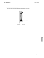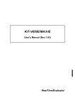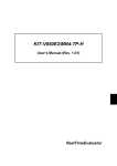
1
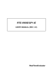
KIT-VR5400-TP
User's Manual
RealTimeEvaluator
KIT-VR5400-TP
User’s Manual
Software Version Up
* The latest RTE for Win32 (Rte4win32) can be down-loaded from following URL.
http://www.midas.co.jp/products/download/english/program/rte4win_32.htm
Notice
* The copyright associated with KIT-VR5400-TP (including software and documentation) are proprietary to
Midas Lab. Co., Ltd.
* This software and manual are protected under applicable copyright laws, and may not be copied,
redistributed or modified in whole or in part, in any way without explicit prior written permission from Midas
Lab. Co., Ltd.
* The right of use granted for the customer means the right to use the software only on one system per one
license. It is prohibited to use the one license of software on two or more systems at the same time.
* While this product was manufactured with all possible care, Midas Lab. Co. Ltd. and its distributor assume
no responsibility whatsoever for any result of using the product.
* The contents and specifications of this product and this document are subject to change without notice.
Trademarks
* MS-Windows, Windows, MS and MS-DOS are the trademarks of Microsoft Corporation, U.S.A. The
names of the programs, systems, CPUs, and other products that appear in this document are usually
trademarks of the manufacturer of the corresponding product.
1
KIT-VR5400-TP
User’s Manual
Revision History
Rev.0.8
Jul. 19,1999
Preliminary 1st edition
Rev.0.81 Jul. 26, 1999
Modified
Rev.0.82 Aug. 11, 1999
Modification to description of pin mask
Rev.1.00 Sep. 24, 1999
Official 1st edition
* Addition of parameter to env command
* Addition of cacheinit and cacheflush
Rev.2.0
Mar.12,2000
2nd edition
* Revised for supporting RTE-1000-TP
Rev.2.01 May.20,2000
Correction by the clerical error
*Modification to description of pin mask
Rev.2.11 Oct. 20,2000
addition of some items to section of Precautions related to
Rev.2.12 May 20, 2001
modified download site
functions in Chapter 6
2
KIT-VR5400-TP
User’s Manual
CONTENTS
1. OVERVIEW....................................................................................................................................... 4
2. HARDWARE SPECIFICATIONS ....................................................................................................... 5
Emulation........................................................................................................................................... 5
3. RTE FOR WIN32............................................................................................................................... 6
Invoking ChkRTE2.exe ....................................................................................................................... 6
4. INITIALIZATION COMMANDS.......................................................................................................... 8
To use Multi........................................................................................................................................ 8
To use PARTNER............................................................................................................................... 8
5. INTERFACE SPECIFICATIONS ........................................................................................................ 9
Pin arrangement table ........................................................................................................................ 9
Connectors......................................................................................................................................... 9
Wiring on Target System .................................................................................................................... 9
Layout of the connectors on the board .............................................................................................. 10
6. PRECAUTIONS .............................................................................................................................. 11
Precautions related to operation ....................................................................................................... 11
Precautions related to functions ........................................................................................................ 11
3
KIT-VR5400-TP
User’s Manual
1. OVERVIEW
KIT-VR5400-TP is the software to debug the system that has NEC RISC micro processor VR5432 by
in-circuit emulation with RTE-100-TP or RTE-1000-TP.
This document describes how to use the KIT-VR5400-TP. Thus on using the product, please refer to the
documents for RTE-100-TP or RTE-1000-TP also, that is main part of whole debugging system.
This product comes with the following components. First check that none of the components are
missing.
• RTE for Win32 Setup Disk
• User's manual (This manual)
• License sheet
4
KIT-VR5400-TP
User’s Manual
2. HARDWARE SPECIFICATIONS
Emulation
Target device
RTE-TP
Emulation functions
Operating frequency
Interface
*7
JTAG clk
Break functions
H/W break points(*1)
Breaks that can be set using access event(*2)
S/W break points
Step breaks
Manual breaks
Trace functions(*3)
Trace data bus
Trace memory
Trace delay
*7
Trace clock
*7
Trace time tag
Trigger setting
Trigger that can be set using an execution
address(*1)
Trigger setting by access event(*2)
Trigger setting by external input
Disassembled trace data display function
ROM emulation functions
*7
Memory capacity
*7
Access time
*7
Operation voltage
*7
Electrical condition
Number of ROMs that can be emulated
DIP-32pin-ROM (8-bit ROM)
DIP-40/42pin-ROM (16-bit ROM)
*7
Extend STD-16BIT-ROM connector
Types of ROMs that can be emulated
DIP-32-ROM probe (8bits-bus)
DIP-40-ROM probe (16bits-bus)
DIP-42-ROM probe (16bits-bus)
*7
Extend STD-16BIT-ROM (16bits-bus)
Bus width specification (bits)
Pin mask functions
VR5432
RTE-1000-TP
167 MHz (max.)
JTAG/N-Wire
100 KHz - 25 MHz
1
1
100
Supported
Supported
4 bits
4 bits x 128K words
0 - 1FFFFh
77 MHz (max.)
100 us - 30 h
Supported
1
1
1
Provided
8 M - 32 M-Byte
40 ns (burst cycle:35sns)(*4)
1.8 - 5 V (*5)
LV-TTL (*6)
4 (max.)
2 (max.)
2 (max.)
1M, 2M, 4M, 8M (27C010/020/040/080)
1M, 2M, 4M (27C1024/2048/4096)
8M, 16M (27C8000/16000)
1M, 2M, 4M, 8M, 16M, 16M, 32M, 64M, 128M, 256M
8/16/32
NMI, INT
*1. The execution address event for a break and triggers is combination.
*2. The access event for a break and triggers is combination.
*3. Execution speed falls during trace.
*4,5,6: These specifications are on the case using expansion 16bit standard ROM cable (CBL-STD16-32M)
and DIP40/42 adapter.
*7: These specifications are on the case using RTE-1000-TP. For RTE-100-TP, please refer to the
document of RTE-100-TP, as the specifications might differ from above.
5
KIT-VR5400-TP
User’s Manual
3. RTE FOR WIN32
This chapter describes the setting of RTE for WIN32, with the focus on the aspects specific to KITVR5400-TP.
Invoking ChkRTE2.exe
After finishing to connect and apply the power supply for all equipments, invoke ChkRTE2.exe to setup
the configuration of "RTEforWIN32".
Please setup the "RTEforWIN32" configuration at least one time for newly installed hardware.
<Setup RTE-Products>
<Selecting RTE>
From Product List, select the “VR5432-TP” located beneath the TP tree.
<Selecting I/F-1, I/F-2>
Select and specify the host interface that suitable for your system from pull-down
menu. (The display in example shows that RTE-PCAT is assigned to address 200h)
<License>
Click the button to setup license checking with the license setup sheet attached to the
KIT package. For detail, please refer to the document of "RTE for WIN32".
6
KIT-VR5400-TP
User’s Manual
<Function test>
If RTE-1000-TP is properly connected to the user system and capable of debugging, the following dialog
box appears upon the normal completion of the function test. In this state, control from the debugger is
possible.
If an error occurs during the test, the N-Wire cable is not properly connected. Check its connection.
Perform the ChkRTE2.exe function test after the RTE-200-TP or
RTE-1000-TP has been connected to the user system and the power
to all the devices has been turned on.
7
KIT-VR5400-TP
User’s Manual
4. INITIALIZATION COMMANDS
Before debugging can be started, system initialization is required.
The following commands are available for system initialization, be sure to setup correctly before
start to use the system.
To use Multi
Use following commands in Target window.
ENV command
* Setup port mask
* Specify JTAG clock
* Specify work area for cash processing
* Specify the high-speed download mode
* Others
ROM command
* Specify ROM emulation condition
NC/NCD command
* Specify data cache area for debugger software
NSPB/NSPBD command
* Specify forbid software break area
NROM/NROMD command
* Specify forced user area in rom emulation mapping area by ROM commad
To use PARTNER
Use following dialog.
Set CPU Environ dialog
* Setup port mask
* Specify JTAG clock
* Specify work area for cash processing
* Specify the high-speed download mode
* Others
Set Emulation ROM dialog
* Specify ROM emulation condition
NC/NCD command
* Specify data cache area for debugger software
NSPB/NSPBD command
* Specify forbid software break area
NROM/NROMD command
* Specify forced user area in rom emulation mapping area by ROM commad
8
KIT-VR5400-TP
User’s Manual
5. INTERFACE SPECIFICATIONS
This chapter describes the specifications of the connectors used for control that are required for the user
system.
Pin arrangement table
Pin number
Signal name
Input/output (user side)
Treatment (user side)
A1
CLKOUT
Output
22 - 33 Ω series resistor (recommended)
A2
TRCDATA0
Output
22 - 33 Ω series resistor (recommended)
A3
TRCDATA1
Output
22 - 33 Ω series resistor (recommended)
A4
TRCDATA2
Output
22 - 33 Ω series resistor (recommended)
A5
TRCDATA3
Output
22 - 33 Ω series resistor (recommended)
A6
TRCEND
Output
22 - 33 Ω series resistor (recommended)
A7
DDI
Input
4.7k - 10 kΩ pullup
A8
DCK
Input
4.7k - 10 kΩ pullup
A9
DMS
Input
4.7k - 10 kΩ pullup
A10
DDO
Output
A11
DRST-
Input
22 - 33 Ω series resistor (recommended)
Open or It connects ColdReset* via an
external circuit.
This signal is negative logic.
A12
Rmode*/
Input/Output
4.7k - 10 kΩ pullup
BkTGIO*
A13
NC.
------
Open
Pin number
Signal name
Input/output (user side)
B1-B10
GND
------
Connection to the power GND
B11
NC.
------
Open
B12
NC.
------
Open
B13
+3.3V
------
Connection to the power
Treatment (user side)
Connectors
Manufacturer: KEL
Models:
8830E-026-170S (straight)
8830E-026-170L (right angle)
8831E-026-170L (right angle, fixing hardware attached)
Wiring on Target System
1.Keep the wire from the CPU to the connector as short as possible.
>>100 mm or shorter is recommended.
2.Output signals from CPU are recommended to be connected to connectors, via high-speed CMOS
buffers of which power supply is the same one with CPU I/O buffers.
9
KIT-VR5400-TP
User’s Manual
Layout of the connectors on the board
The figure below shows the physical layout of the connectors on the board.
B13 A13
B12 A12
Polarity indication
B2 A2
B1 A1
Board end
[Top View]
10
KIT-VR5400-TP
User’s Manual
6. PRECAUTIONS
This chapter provides precautionary information on the use of KIT-VR5400-TP.
Precautions related to operation
1) Do not turn on the power to the user system while the power to KIT-VR5400-TP is off. Doing so can
cause a malfunction.
2) KIT-VR5400-TP externally controls the debugging control circuit built into the CPU Consequently,
KIT-VR5400-TP does not operate correctly unless the following conditions are satisfied:
* KIT-VR5400-TP is properly connected to the user system using the N-Wire cable.
* The power to the user system is on so that the CPU can run correctly.
Precautions related to functions
1)
It is related with real-time trace.
* The disassemble display of real-time trace is performed by reading the contents of a memory on
the basis of the branch information from CPU. Therefore, when the contents of a memory are
changed after execution, the right execution history cannot be displayed. Moreover, when an
error is in branch information, an analysis display cannot be done correctly.
* When it runs from a break point one instruction of an execution start address does not write into
trace.
* Trace is automatically ended on condition that the following.
- When the trigger point was passed and a break is taken.
- When a break is taken in the state of the delay mode.
2)
A hardware break point that break point of EVE command and break point set on ROM area
functions on 8 bytes of boundary.
3)
Don't LOCK cache. When it LOCKs, neither break in the area, nor step execution and rewriting of a
memory can be performed normally.
4)
For further information, be sure to refer to the Release Note of the KIT.
11