1
aaaaaaaaaaaaaaaaaaaaaaaaaaaaaaaaaaaaaaaaaaaaaaaa
ISDN 8500-Series T-Interface Terminals
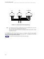
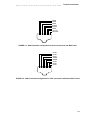
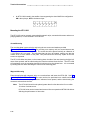
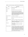
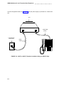
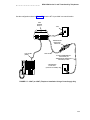
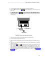
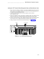
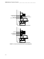
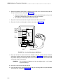
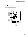
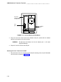
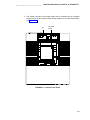
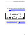
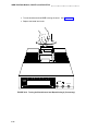
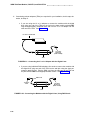
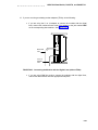
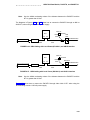
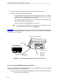
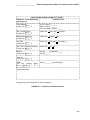
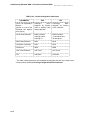
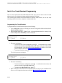
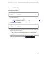
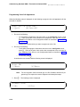
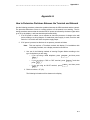
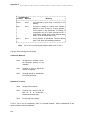
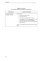
2. Verify that the present position of the jumpers is correct.
d
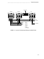
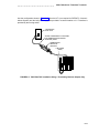
Verify that the terminating resistor jumpers are set to OFF, when the voice terminal is in a Point-to-Point configuration and the terminating resistor is placed in the
closet or a 440A4 is connected on the line.
d
Verify that the terminating resistor jumpers are set to ON, when the voice terminal is in a Point-to-Point configuration and the terminating resistor is not in the
closet or a 440A4 is not connected on the line.
d
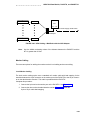
Verify that the terminating resistor jumpers are set to OFF, when the voice terminal is in a MultiPoint configuration and the terminating resistor is either in the
closet, a 440A4 is connected on the line, or the jumpers are set to ON in any of
the other voice terminals on the line.
Note:
d
Only one terminating resistor is used for MultiPoint configuration.
Verify that the terminating resistor jumpers are set to ON, when the voice terminal is in a MultiPoint configuration and the terminating resistor is not in the closet,
and a 440A4 is not connected on the line, and the jumpers are not set to ON in
any of the other voice terminals on the line.
Setting the Power Option Jumpers
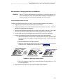
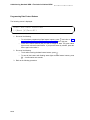
The power option setting for both the DEFINITY and the 5ESS switches must be AUX for MultiPoint configurations; for Point-to-Point configurations, the AUX setting is recommended, but the
voice terminal can be set for PHAN.
Note:
The original factory default setting for 8510T terminals is AUX.
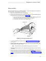
If necessary, use the following procedure to change the setting of the Power Option jumpers.
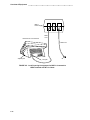
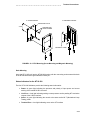
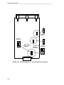
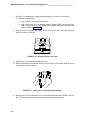
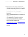
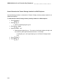
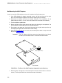
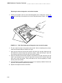
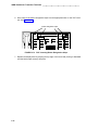
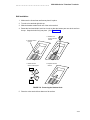
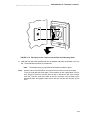
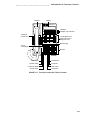
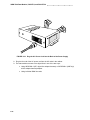
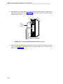
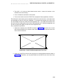
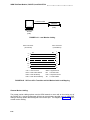
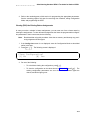
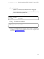
1. Locate the power option jumpers at the bottom center. On the right side of the pins, on
the plastic housing, you will see the label POWER and a diagram of the correct settings.
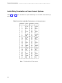
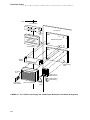
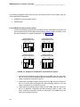
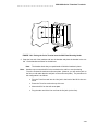
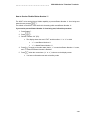
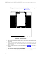
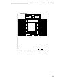
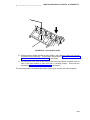
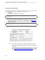
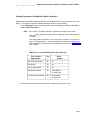
The following is a description of the settings: (See also Figure 7-16.)
The power option resistors are set to AUX if each of the two jumpers covers the
two lower pins in each set. (The first pin in each set is left uncovered.)
The power option resistors are set to PHAN if each of the two jumpers covers
the two top pins in each set. (The third pin in each set is left uncovered.)
7-29