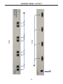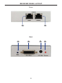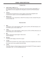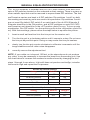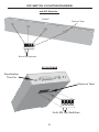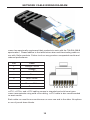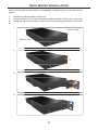
1
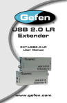
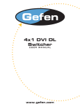
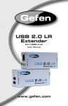
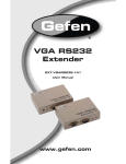
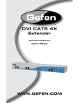
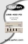
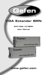
®
EXT-DVI-CAT5-4X
User Manual
www.gefen.com
ASKING FOR ASSISTANCE
Technical Support:
Telephone
Fax
(818) 772-9100
(800) 545-6900
(818) 772-9120
Technical Support Hours:
8:00 AM to 5:00 PM Monday thru Friday.
Write To:
Gefen, LLC.
c/o Customer Service
20600 Nordhoff St
Chatsworth, CA 91311
www.gefen.com
[email protected]
Notice
Gefen, LLC reserves the right to make changes in the hardware, packaging, and
any accompanying documentation without prior written notice.
4x4 DVI Extender S is a trademark of Gefen, LLC
© 2011 Gefen, LLC. All rights reserved.
All trademarks are the property of their respective companies.
Rev A5
CONTENTS
1
Introduction
2
Operation Notes
3
Features
4
Sender Panel Layout
5
Receiver Panel Layout
6
Panel Descriptions
7
Connecting the 4x4 DVI Extender S
7
4x4 DVI Extender S Configuration
8
Manual Equalization Procedure
9
DIP Switch Location Diagram
10 Network Cable Wiring Diagram
11 Rack Mount Installation
12 Mounting Plate Installation
13 Specifications
14 Warranty
INTRODUCTION
Congratulations on your purchase of the 4x4 DVI Extender S Extender. Your
complete satisfaction is very important to us.
Gefen
Gefen delivers innovative, progressive computer and electronics add-on solutions
that harness integration, extension, distribution and conversion technologies.
Gefen’s reliable, plug-and-play products supplement cross-platform computer
systems, professional audio/video environments and HDTV systems of all sizes
with hard-working solutions that are easy to implement and simple to operate.
The Gefen 4x4 DVI Extender S
The 4x4 DVI Extender S Extender is the perfect solution for anyone who needs to
send multiple (up to four) DVI video sources to multiple (up to four) DVI displays
in remote locations at the same time.
The 4x4 DVI Extender S Extender has 4 DVI video inputs. The DVI sources are
sent to up to four DVI CAT5 MS receivers via industry standard CAT-5, CAT5e or CAT-6 cables. Distances of up to 300 feet for 1080i video, and 150 feet
for 1080p video are possible. Signal auto-equalization is set by default and will
provide optimal image reproduction for cable runs of 130 feet or less. Manual
equalization is available for cable runs at greater distances.
How It Works
Connect your DVI video sources to the 4x4 DVI Extender S inputs using the
supplied DVI cables. Run two CAT-5, CAT-5e or CAT-6 network cables from the
4x4 DVI Extender S Extender to each of the DVI CAT5 MS Receivers. Lastly,
connect up to four DVI displays to the DVI CAT5 MS receivers at the remote
locations.
1
OPERATION NOTES
READ THESE NOTES BEFORE INSTALLING OR
OPERATING THE 4X4 DVI EXTENDER S
•
The 4x4 DVI Extender S Extender and DVI CAT5 MSR units are housed in a
metal box for better RF shielding.
•
The maximum cable extension is 300 feet (91 meters) for video resolutions
of 1080i and below.
•
The maximum cable extension is 150 feet (45 meters) for video resolutions
of 1080p.
•
If EMI is present anywhere near the RJ-45 video cable runs, it may
be necessary to use shielded RJ-45 cable. This is to prevent possible
interference from degrading the video signal. Using shielded cable, however,
will reduce the maximum distance that the RJ-45 cable can be run.
•
Extensions under 130 feet can use Auto EQ (which is on by default).
Extensions over 130 feet will require you to manually EQ your signal (see
page 8).
•
Each cable run must be one continuous run from one end to the other. No
splices or use of punch down blocks.
•
High quality CAT-6a cabling should be used for maximum performance.
•
Do not use stranded or low/no skew cabling. Solid core cabling should be
used for maximum performance.
2
FEATURES
Features
•
Easily distribute four DVI sources to four remote DVI displays
•
Extends video signals up to 300 feet over CAT-5, CAT-5e or CAT-6a network
cable
•
Maintains 1920 x 1200, 1080p, and 2k resolution video
•
HDCP-compliant
Package Includes
(1) 4x4 DVI Extender S - Sender unit
(4) DVI CAT5 MS - Receiver unit
(4) 6 ft. DVI cable (M-M)
(4) 5V DC Power Supplies
(1) 24V DC power supply
(4) Mounting Plates
(1) Set of Rack Ears
3
Back
2
3
Front
1
SENDER PANEL LAYOUT
4
RECEIVER PANEL LAYOUT
Front
1
2
Back
3
4
5
5
6
PANEL DESCRIPTIONS
Sender Unit
1
CAT-5 Video / DDC (1 - 4)
Connect a pair of CAT-5 cables from each set of RJ-45 jacks (Video/DDC) on
the Sender unit to the respective RJ-45 jacks on the DVI CAT5 MS Receiver
unit.
2
24V DC
Connect the included 24V DC power supply to this power receptacle and
connect the AC power cord to an available electrical outlet.
3
DVI In (1-4)
Connect up to four computers (or other DVI sources) to each of these DVI ports
on the Sender unit.
Receiver Unit
1
DDC
Connects a CAT-5 cable between a DDC jack on a DVI CAT5 MS Receiver unit
and a DDC jack on the Sender unit.
2
Video
Connects a CAT-5 cable between a Video jack on a DVI CAT5 MS Receiver unit
and a Video jack on the Sender unit.
3
EQ
Used to adjust the output signal. Refer to the DVI CAT5 MS User Manuall for
more information.
4
DVI Out
Connect a DVI display to the DVI Out port.
5
+5 Vdc
Connect the included 5V DC power supply to this power receptacle and connect
the power cord to an available electrical outlet.
6
Power
This LED indicator will glow bright red when the included 5V DC power supply is
connected to the DVI CAT5 MS
S Receiver unit.
6
CONNECTING THE 4X4 DVI EXTENDER S
How to Connect the 4x4 DVI Extender S
1.
Connect your sources (up to four) to the 4x4 DVI Extender S DVI inputs
using the supplied DVI cables.
2.
Connect up to four displays to the DVI output ports on each DVI CAT5 MS
Receiver unit.
3.
Connect both CAT-5 (CAT-5e or CAT-6) cables (DDC and Video) between
the 4x4 DVI Extender S Extender and each DVI CAT5 MS Receiver unit.
NOTE: If field terminating network cable, please adhere to the TIA/EIA-568-B
standard. Please see page 10 for more information.
4.
Connect the 24V DC power supply to the 4x4 DVI Extender S.
5.
Connect the 5V DC power supplies to each of the DVI CAT5 MS Receiver
unit.
6.
Power on the displays.
7.
Power on the sources.
NOTE: If an image is not being shown on the display, please check all cabling for
proper connections and follow the steps outlined below and in the next section.
4X4 DVI EXTENDER S CONFIGURATION
The 4x4 DVI Extender S and DVI CAT5 MSR receivers have built-in auto
equalization that will automatically tune out any unwanted video noise. This
feature is reliable with premium cable runs up to a maximum of 130 feet. It may
be necessary to disable this feature if there is either no video being displayed on
initial start-up, there is video noise in the image, or the cable run exceeds 130
feet. First, verify that all the proper connections have been made and that all
devices are powered on before attempting to disable auto equalization. Please
follow the section on the next page to manually equalize the video signal.
7
MANUAL EQUALIZATION PROCEDURE
The 4x4 DVI Extender S Extender and DVI CAT5 MSR receiver units both have
sets of DIP switches located on the underside of their casings. There is a piece of
silver metallic tape that must be removed to expose these DIP switches. The 4x4
DVI Extender S Extender unit carries 4 banks of 4 DIP switches. Each DVI CAT5
MSR receiver carries one bank of 4 DIP switches. Dip switches 1 and 2 on both
the sending and receiving units are used in this procedure. Dip switches 3 and 4
are not used. By default, DIP switch 2 on each bank of the 4x4 DVI Extender S
Extender should be in the ON position, and all DIP switches on each DVI CAT5
MSR receiving unit should be in the OFF position (Auto EQ On). To turn off auto
equalization, turn DIP switch 1 on the receiving units to the ON position (Auto EQ
off). With these settings, please follow the steps below to equalize the picture.
1.
Insert a small flat head tool into the trim pot on the receiver unit.
2.
Turn the trim pot in a clockwise fashion until it comes to a stop. Do not force
the trim pot beyond this point. Doing so may render the trim pot useless.
3.
Slowly turn the trim pot counter-clockwise in millimeter increments until the
image stabilizes and all video noise disappears.
4.
Carefully remove the adjustment tool.
NOTE: If your cable run is beyond 130 feet, or the steps above do not produce
any video, it may be necessary to increase the boost from the sending unit. Use
the chart below to increase the senders to medium boost by changing the 4x4
DVI Extender S Extender’s DIP switches. Once a new boost setting is set, repeat
steps 1 through 4 from above. If this still does not produce and image, increase
the boost to high and repeat the EQ process.
Sender Dip Switch Settings
Setting
Switch 1
Switch 2
Medium Boost
OFF
OFF
No Boost (Default)
OFF
ON
High Boost
ON
OFF
NOT USED
ON
ON
Receiver Dip Switch Settings
Setting
Switch 1
Switch 2
Manual EQ
ON
OFF
Auto EQ (Default)
OFF
OFF
8
DIP SWITCH LOCATION DIAGRAM
4x4 DVI Extenderr S
FRONT
Remove Tape
1
2
3
4
Boost Dip Switches
DVI CAT5 MSR
Equalization
Trim Pot
Remove Tape
1
2
3
4
Auto EQ Dip Switches
9
NETWORK CABLE WIRING DIAGRAM
Gefen has specifically engineered their products to work with the TIA/EIA-568-B
specification. Please adhere to the table below when field terminating cable for
use with Gefen products. Failure to do so may produce unexpected results and
reduced performance.
Pin
Color
1
Orange / White
2
Orange
3
Green / White
4
Blue
5
Blue / White
6
Green
7
Brown / White
8
Brown
12345678
CAT-5, CAT-5e, and CAT-6 cabling comes in stranded and solid core types.
Gefen recommends using solid core cabling. CAT-6 cable is also recommended
for best results.
Each cable run must be one continuous run from one end to the other. No splices
or use of punch down blocks.
10
RACK MOUNT INSTALLATION
Rack mount ears are provided for installation of this unit into a 1U rack mount
space.
1.
2.
3.
4.
Locate the side screws on the unit.
Remove the front 2 screws that are located closest to the front of the unit.
Using the removed screws, screw the rack mounting bracket into the unit.
Repeat the procedure
p
on the opposite
pp
side of the unit.
1
Front of unit
Rear of unit
2
3
4
11
MOUNTING PLATE INSTALLATION
Mounting Plate Installation
1
Remove the rubber
feet covering the screws
off the bottom of the
unit.
Remove the screws.
2
3
Line up the mounting
plates and screw it on to
the unit.
12
SPECIFICATIONS
Video Amplifier Bandwidth ..............................................................4 x 165 MHz
Input Video Signal ................................................................................ 1.2 V p-p
Input DDC Signal ........................................................................... 5V p-p (TTL)
Single Link Range ..............................................................1080p / 1920 x 1200
DVI Connector Type ...................................... DVI-I 29 Pin Female (digital only)
Link Connector .......................................................................................... RJ-45
Power Consumption ......................................................................... 60W (max)
Transmitter Power Supply ...................................................................... 24V DC
Receiver Power Supply ........................................................................... 5V DC
Dimensions ..............................................................17” W x 1.75” H x 5.875” D
Shipping Weight ........................................................................................10 lbs.
13
WARRANTY
Gefen warrants the equipment it manufactures to be free from defects in material
and workmanship.
If equipment fails because of such defects and Gefen is notified within two (2)
years from the date of shipment, Gefen will, at its option, repair or replace the
equipment, provided that the equipment has not been subjected to mechanical,
electrical, or other abuse or modifications. Equipment that fails under conditions
other than those covered will be repaired at the current price of parts and labor in
effect at the time of repair. Such repairs are warranted for ninety (90) days from
the day of reshipment to the Buyer.
This warranty is in lieu of all other warranties expressed or implied, including
without limitation, any implied warranty or merchantability or fitness for any
particular purpose, all of which are expressly disclaimed.
1.
Proof of sale may be required in order to claim warranty.
2.
Customers outside the US are responsible for shipping charges to and from
Gefen.
3.
Copper cables are limited to a 30 day warranty and cables must be in their
original condition.
The information in this manual has been carefully checked and is believed to
be accurate. However, Gefen assumes no responsibility for any inaccuracies
that may be contained in this manual. In no event will Gefen be liable for
direct, indirect, special, incidental, or consequential damages resulting from
any defect or omission in this manual, even if advised of the possibility of such
damages. The technical information contained herein regarding the features and
specifications is subject to change without notice.
For the latest warranty coverage information, refer to the Warranty and Return
Policy under the Support section of the Gefen Web site at www.gefen.com.
PRODUCT REGISTRATION
Please register your product online by visiting the Register Product page
under the Support section of the Gefen Web site.
14
Rev A5
20600 Nordhoff St., Chatsworth CA 91311
1-800-545-6900
818-772-9100
www.gefen.com
Pb
This product uses UL or CE listed power supplies.
fax: 818-772-9120
[email protected]