1
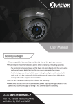
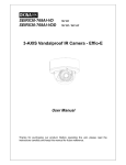
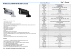
CONTENTS 1. DESCRIPTION ......................................................................................... 1 2. MAIN FEATURES .................................................................................... 3 3. INSTALLATION ....................................................................................... 4 V5411-A8 SERIES 3.1 MOUNTING PROCESS ......................................................................... 4 INDOOR ELECTRONIC DAY/NIGHT MINIDOME FIXED CAMERA 3.2 HANDLING PRECAUTIONS ................................................................ 7 3.3 INSTALLATION PRECAUTIONS ......................................................... 7 4. MENU SETTINGS .................................................................................... 8 User Manual 4.1 LENS..................................................................................................... 12 4.2 SHUTTER/AGC ................................................................................... 13 4.3 PICTURE ADJUSTMENT .................................................................... 15 4.3.1 MIRROR ....................................................................................... 15 4.3.2 BRIGHTNESS .............................................................................. 15 4.3.3 CONTRAST ................................................................................. 16 4.3.4 SHAPRNESS ................................................................................ 16 4.3.5 HUE .............................................................................................. 16 4.3.6 GAIN ............................................................................................ 16 4.4 WHITE BALANCE............................................................................... 17 4.5 NR ......................................................................................................... 19 4.6 CAMERA ID ......................................................................................... 19 4.7 LANGUAGE ......................................................................................... 20 4.8 BACKLIGHT ........................................................................................ 21 4.9 MOTION DETECTION ........................................................................ 21 4.10 PRIVACY MASK ................................................................................ 22 4.11 ATR ..................................................................................................... 23 4.12 SYNC MODE ...................................................................................... 23 1. DESCRIPTION 4.13 DAY/NIGHT ....................................................................................... 23 Thank you very much for purchasing our product. 4.14 CAMERA RESET ............................................................................... 24 Infinova's V5411-A8 series indoor electronic day/night fixed minidome APPENDIX I SPECIFICATIONS .............................................................. 25 cameras feature a high resolution 1/3" SONY Exview HAD II CCD sensor. APPENDIX II CABLE DIAMETER CALCULATION AND Advanced Effio Digital Signal Processing (DSP) provides 700 TV lines of LIGHTNING & SURGE PROTECTION.................................................. 27 resolution, excellent low light performance, and superior color rendering ability and digital noise reduction function, which ensures high-quality images even under challenging lighting environments. V5411-A8 series provides privacy mask which effectively protects certain private areas from being seen and motion detection which provides higher security for your surveillance. V5411-A8 series offers user-friendly OSD menu, easy to adjust the video parameters. In addition, its elegant design and compact structure makes it an ideal surveillance solution for shopping malls, banks, office buildings, parking lots, city streets and other applications. This manual is for the following models: V5411-A8004ST Analog minidome camera, 2-axis, Indoor, 1/3 inch CCD, Electronic day/night, 700TVL, NTSC, 12VDC/24VAC, Surface mount, 2.8mm fixed lens V5411-A8014ST Analog minidome camera, 2-axis, Indoor, 1/3 inch CCD, Electronic day/night, 700TVL, PAL, 12VDC/24VAC, Surface mount, 2.8mm fixed lens V5411-A8004SU Analog minidome camera, 2-axis, Indoor, 1/3 inch CCD, Electronic day/night, 700TVL, NTSC, 12VDC/24VAC, Surface mount, 3.6mm fixed lens V5411-A8014SU Analog minidome camera, 2-axis, Indoor, 1/3 inch CCD, Electronic day/night, 700TVL, PAL, 12VDC/24VAC, Surface mount, 3.6mm fixed lens 1 V5411-A8004SX Analog minidome camera, 2-axis, Indoor, 2. MAIN FEATURES 1/3 inch CCD, Electronic day/night, 700TVL, NTSC, 12VDC/24VAC, Surface mount, 8mm fixed lens V5411-A8014SX Analog minidome camera, 2-axis, Indoor, 1/3 inch CCD, Electronic day/night, 700TVL, PAL, 12VDC/24VAC, Surface mount, 8mm fixed lens 1/3" SONY Exview HAD II CCD sensor Resolution: 700TVL Electronic day/night functionality Compact structure, elegant design, easy to install OSD menu in multiple languages 2D digital noise reduction, high S/N ratio, clear image Highlight Compensation (HLC) Motion detection Privacy mask Auto Electronic Shutter (AES), Auto Gain Control (AGC), Backlight Compensation (BLC) Multiple white balance modes and superior color rendering ability CCD blemish compensation Mirror, Hue, and Color Gain adjustable 12VDC/24VAC power supply, centralized power supply supported Internal / Line Lock Sync. System 2 3 3. INSTALLATION 3.1 Mounting Process STEP 1: Secure Dome’s Adapter in the desired ceiling position with the 3 fixed screws as shown in Figure 1. Figure 1 Figure 3 The adapter mounting holes are as shown in Figure 2: Notes: The minidome camera supports sync system of INT/L.L., which can be 120° set by the DIP switch on the back panel of the minidome camera. 3- Ø4.40 Ø106.00 STEP 3: The vertical angle can be adjusted by loosening the screws as shown in Figure 4 and by turning the Camera Case vertically. 120° (Unit: mm) Figure 2 STEP 2: Remove the Dome Cover. Align the 3 grooves of the camera unit with the 3 bolts in the adapter and turn counterclockwise to tighten it. 4 Figure 4 STEP 4: The horizontal angle can be adjusted by turning the Camera Case and 5 bracket in Figure 5 and by turning the Camera Platform horizontally. 3.2 Handling Precautions 1. Never let liquid of any kind flow into this unit. 2. Do not directly touch the CCD element. If it is necessary to clean the element, use a soft cloth moistened with alcohol to wipe off the dust. 3. If any abnormality occurs, make sure to unplug the unit and contact your local dealer. 4. This camera possesses AGC circuit. Therefore, when the camera is used under lower luminance, the sensitivity will strengthen automatically and make the image very rough in vision. It is normal. Figure 5 5. When the camera is used in ATW mode, due to the working principle of STEP 5: Then you can adjust the parameters in the OSD menu to set the automatic tracking white balance, the recorded color is slightly different from desired video quality according to your surveillance requirements. The detailed instructions are specified in Chapter IV. the real color. It is normal. 6. If the subject is with high luminance (like lamp), vertical stripes will occur on the monitor (tailing shadow) or the surrounding image becomes vague STEP 6: Place the Dome bubble over the Camera and tighten it by turning it to the right. In this process, the shielding cover may block the camera. User (flowering). It is special phenomenon of CCD, not error. 7. The power for this camera is 12VDC or 24VAC. Also, it supports centralized can adjust the position of shielding cover by turning the bubble. With the power supply. shielding cover at the proper position, the installation is finished. (Note: if 2.8mm fixed lens is built-in, the shielding cover is not utilized.) 3.3 Installation Precautions Dimensions: (Unit: mm) 1. Do not drop the unit or subject it to strong knock. 2. Do not point the camera lens toward the sun or other strong light. 3. Do not install the camera in environment with temperature beyond the acceptable range (from -10°C to 50°C), or with high humidity, direct rainfall, frequent vibrations and shocks. Figure 6 6 7 Menu 4. MENU SETTINGS Menu LENS AUTO Submenu TYPE MODE SPEED DC, VIDEO AUTO/OPEN/CLOSE 000~255 MANUAL AUTO SHUTTER/AGC MANUAL PICT ADJUST ATW WHITE BAL Submenu PUSH LOCK HIGH LUMINANCE AUTO IRIS / SHUT+AUTO MODE IRIS BRIGHTNESS 000~255 LOW LUMINANCE MODE AGC/ OFF BRIGHTNESS ×0.25, ×0.50, ×0.75, ×1.00 MODE SHUT +AGC PAL: 1/50~1/100,000; SHUT NTSC: 1/60~1/100,000 AGC 0.00~42.00 (8-level) MIRROR OFF/ON BRIGHTNESS 000~255 (Default: 000) CONTRAST 000~255 (Default: 128) SHARPNESS 000~255 (Default: 048) HUE 000~255 (Default: 128) GAIN 000~255 (Default: 128) SPEED 000~255 DELAY CNT 000~255 ATW FRAME ×0.50~×2.00 (4-level) ENVIRONMEN INDOOR/OUTDOOR T NR CAMERA ID LANGUAGE BACKLIGHT MOTION DET NR MODE OFF BLC HLC OFF DETECT SENSE BLOCK DISP MONITOR AREA AREA SEL ON USER 1 USER 2 ANTI-CR MANUAL LEVEL 8 000~255 000~255 000~255 000~255 TOP BOTTOM LEFT RIGHT AREA SEL TOP BOTTOM PUSH B-GAIN R-GAIN B-GAIN R-GAIN PRIVACY Y/C, OFF, Y, C ON OFF CHINESE/ ENGLISH/ JAPANESE ON LEFT RIGHT COLOR TRANSP MOSAIC 9 000~127 OFF/ON/ENABLE OFF/ON 1/4~4/4 PAL: 000~288; NTSC: 000~244 PAL: 000~288; NTSC: 000~244 PAL: 000~468; NTSC: 000~474 PAL: 000~468; NTSC: 000~474 1/4~4/4 PAL: 000~288; NTSC: 000~244 PAL: 000~288; NTSC: 000~244 PAL: 000~468; NTSC: 000~474 PAL: 000~468; NTSC: 000~474 1~8 0.00-1.00 (4-level) OFF/ON Menu Submenu OFF LUMINANCE ATR ON SYNC CONTRAST LOW/MID/HIGH LOW/MID LOW/ MID/ MID HIGH/HIGH INT COLOR DAY/NIGHT AUTO B/W UP L IMPULSE DELAY CNT DAY→ NIGHT NIGHT→ DAY OFF/ON 000~255 IMPULSE OFF/ON R DOWN 000~255 000~255 CAMERA RESET Camera Menu Notes: Sync system can be set to INT or LL by the DIP switch on the back panel of the camera module. It can be enabled or disabled to display in the menu, but not adjusted. 1. Press the button, and the MAIN MENU will appear. Menu setting Five-way switch is used to control the camera menu. The switch is on the camera cable, as shown in the figure below: 2. Press the button UP/DOWN to move through the items or LEFT/RIGHT to change the selected item’s value. 10 11 3. If “ ” is available in an item's value, press the OSD button to enter the submenu and repeat the previous operations to set it. Select “RETURN ” to get back to the previous menu. 4. Select NEXT in the SETUP MENU 1 and press the OSD button to enter the SETUP MENU 2; select BACK in the SETUP MENU 2 and press the OSD button to get back to the SETUP MENU 1. 5. Select Exit and press the OSD button to exit the menu. 6. Save All: save all the parameter settings. After all parameters settings are finished properly, please press “Save All” to save all settings and exit the menu. This operation ensures all camera parameters kept unchanged in case of power disconnection. 7. Once the intervals of the operation to OSD menu reach 1 minute, the OSD menu will disappear. 8. Blemish compensation is available. Without menu display, press and hold down the UP/DOWN button to enable the blemish compensation function. 9. To save the modified items, you have to click SAVE ALL before power-off; otherwise, the settings will be restored to the previous status after the power is back; also, you have to click SAVE ALL in case of resetting. Type: to display the lens drive type. Options: DC/VIDEO. DC means direct current driven auto iris; VIDEO means video driven lens. Notes: The built-in lens is DC driven. Please do not set the type to VIDEO. Mode: AUTO, OPEN, CLOSE. Speed: 000~255. Notes: Users can adjust the iris speed for a camera, as an improper speed may cause the video too bright or dark. 2) Manual: Manual iris lens. 4.1 LENS Function: to set lens type. Options: Auto 1) Auto 4.2 SHUTTER/AGC , Manual. : Auto iris lens. If selected, parameters including type, mode and speed of auto iris can be set. Function: to set the shutter/AGC parameters. Options: Auto , Manual . 1) Auto : if set to Auto , enter the submenu, as shown in the figure below: 12 13 Shutter: 1/50s~1/100,000s (PAL), 8-level adjustable; 1/60s~1/100,000s (NTSC), 8-level adjustable. The shutter speed gets faster with the decrease of value, while the exposure time gets shorter and the video becomes darker. On the contrary, the shutter speed gets slower with the increase of value, while the exposure time gets longer and the video becomes brighter. AGC: 0.00~42.00, 8-level adjustable. 4.3 PICTURE ADJUSTMENT Press the OSD button to enter the submenu, as shown in the figure below: High Luminance Mode: AUTO IRIS, SHUT+AUTO IRIS; Brightness: 000~255. Low Luminance Mode: AGC, OFF; Brightness: ×0.25, ×0.50, ×0.75, ×1.00. 2) Manual : if set to Manual , enter the submenu, as shown in the figure below: 4.3.1 MIRROR Function: to set the image mirror function. Options: OFF/ON. Default as: OFF. If enabled, horizontal mirror can be realized. 4.3.2 BRIGHTNESS Function: to adjust the brightness. Options: 000-255. The video becomes brighter as the brightness level goes up. Mode: SHUT+AGC; 14 15 4.3.3 CONTRAST 4.4 WHITE BALANCE Function: to adjust the contrast. Function: to set white balance mode to compensate color temperature, further Options: 000~255. rendering the true color of object. 4.3.4 SHAPRNESS LOCK. Options: ATW , USER 1 , USER 2 , ANTI CR, MANUAL , PUSH 1) ATW : Auto Tracking White Balance mode. The built-in sensor can Function: to adjust the sharpness. Options: 000~255. The image becomes clearer along with the increase of sharpness level. perceive the current color temperature and automatically process the images with specific arithmetic, so as to render the true color of objects. Press the OSD button to enter the submenu, as shown in the figure below: 4.3.5 HUE Function: to adjust the hue. Options: 000~255. 4.3.6 GAIN Function: to adjust the color gain. Options: 000~255. The color becomes deeper with the increase of gain level. Speed: 000~255. Delay Count: 000~255. ATW Frame: ×0.50, ×1.00, ×1.50, ×2.00. Environment: Indoor/Outdoor. 16 17 2) USER 1 4.5 NR Press the OSD button to enter the submenu, as shown in the figure below: B-GAIN: to adjust the blue gain. Options: 000~255. R-GAIN: to adjust the red gain. Options: 000~255. Function: to set the noise reduction mode. Notes: Settings under USER 2 is similar to that of USER 1. Options: Y, C, Y/C, OFF. Y indicates the brightness signal and C indicates the chroma signal. 3) MANUAL Manual WB can effectively help render the true color of images when auto WB fails to do so. 4.6 CAMERA ID Function: to enable/disable camera ID display. Options: OFF/ON . Default as: OFF. If set to ON , users can enter the submenu to set the camera ID and the display position. CAMERA ID SETUP INFINOVA ABCDEFGHIJKLMNOPQRSTUV W X Y Z 0 1 2 3 4 5 6 7 8 9 —!”# $ % & ’ ( ) _‵,¥:;< = >?@﹨^*. ×+/ CHR1 CHR2 CLR POS LEVEL: press the L/R button to adjust the level. 4) PUSH LOCK: press the OSD button to lock white balance. RETURN 5) ANTI CR: to enable the ANTI CR function. 18 19 Camera ID setup: the camera title is displayed in two lines, with a maximum 4.8 BACKLIGHT of 26 characters displayed in each line. Function: to set the BLC/HLC function. Character Edit Area: the camera ID allows A~Z, 0~9 and other 28 special Options: OFF, BLC, HLC. BLC provides necessary light level compensation characters, as shown in the figure above. for the subject in the foreground when there is a bright light source in the CHR1/CHR2: character library 1/2. background. HLC blocks the strong spots of light and compensates for the ←→↑↓: to move the identification code cursor; dark area as needed, thus allowing the object to be easily viewed. CLR: to clear the currently selected characters; POS : to adjust the display position of camera ID. 4.9 MOTION DETECTION Function: to enable/disable motion detection function. How to set the camera ID? 1. Enter the camera ID setup interface, move the cursor to “←→↑↓” by pushing the button UP/DOWN, get the cursor to move among the Options: OFF/ON . If set to “ON ”, press the OSD button to enter the submenu, as shown in the figure below: identification codes via “←→↑↓”, and select the character required to be modified or set. The cursor will be located on the first character as defaulted. 2. Move the cursor to character editing area by pushing the button UP/DOWN, select character by pushing the button LEFT/RIGHT and press the OSD button to confirm. Then, the selected character will be displayed in the specified position. 3. Repeat step 1 and 2 to modify or set other characters. To clear characters, just select “CLR” with the direction keys and press the OSD button to confirm. At last, select “POS ” with the direction keys and enter the setting interface to adjust the camera ID display position on the screen. Then, press the OSD button to exit the interface. Detect Sensitivity: 000~127. Block Display: OFF/ON/ENABLE . If ENABLE is selected, press the OSD button and you can set the block display area with the directional buttons. Monitor Area: ON/OFF. Area Select: to select the motion detection areas. 4.7 LANGUAGE Function: to set the language for OSD menu. Options: CHINESE, ENGLISH, JAPANESE, DEUTSCH, FRANCAIS, PYCCKNN, PORTUGUES, ESPANOL. Notes: The language is default as ENGLISH. 20 Options: 1/4~4/4. The camera supports up to 4 areas which can be enabled or disabled separately via mode setting. The coordinates (TOP/BOTTOM/LEFT/RIGHT) determine an area. Users can adjust the TOP/BOTTOM coordinate value to 000~288/000~244 (PAL/NTSC) and the LEFT/RIGHT coordinate value to 000~468/000~474 (PAL/NTSC). 21 Notes: The value of LEFT coordinate should be less than that of RIGHT, and 4.11 ATR TOP less than BOTTOM. The origin of coordinate lies in the upper-left corner Function: to enable/disable ATR (Adaptive Tone Reproduction). of screen. Options: ON /OFF. Defaulted as: OFF. If set to “ON ”, the brightness of videos can be automatically adjusted. For 4.10 PRIVACY MASK dark area, properly enhance the luminance; for bright area, properly reduce the Function: to enable/disable privacy mask function. luminance. Enter the submenu to set the luminance and contrast, as shown in Options: OFF/ON . If set to “ON ”, press the OSD button to enter the the figure below: submenu. The area size, color and transparency of each area can be set independently. Luminance: LOW/MID/HIGH. Contrast: Low/MID LOW/MID/MID HIGH/HIGH. Area Select: 1/4~4/4. A maximum of 4 spherical privacy zones are allowed. The coordinates (TOP/BOTTOM/LEFT/RIGHT) determine an area. Users can 4.12 SYNC MODE adjust the TOP/BOTTOM coordinate value to 000~288/000~244 (PAL/NTSC) Function: to set the synchronization mode for the camera. and the LEFT/RIGHT coordinate value to 000~468/000~474 (PAL/NTSC). Notes: The sync mode can be set via the DIP switch on the back panel of the Color: Red, Green, Blue, Yellow, Cyan, Magenta, White, Black. camera. Transparency: 0.00, 0.50, 0.75, 1.00. Mosaic: ON/OFF. 4.13 DAY/NIGHT Function: switch over B/W and Color mode; predefine the threshold illumination values and lag time for day/night switching. Options: Auto , Color, B/W . Default as: Color. 1) Color: the video is displayed in color mode. 22 23 2) Auto : to automatically switch B/W and Color mode as per the light conditions. Enter the submenu, as shown in the figure below: APPENDIX I SPECIFICATIONS Model Image Sensor Video System Effective Pixels (H × V) IMPULSE: ON/OFF. Impulse is available for black and white image if set to ON and unavailable if set to OFF. DELAY CNT: delay time for day/night switch. Scanning System Resolution Day/Night Functionality Sensitivity S/N Ratio Lens Camera Angle Adjustment DAY—>NIGHT: to set the switchover threshold value from Color to B/W Auto Electronic Shutter mode. The larger the value is, the lower the illumination value for day/night switching is. Options: 000~255. Gamma Correction NIGHT—>DAY: to set the switchover threshold value from B/W mode to White Balance Color mode. The smaller the value is, the larger the illumination value for day/night switching. Options: 000~255. 3) B/W : the video is displayed in black and white. Users can enter the submenu to set the burst, referring to the settings under Auto 4.14 CAMERA RESET Function: to resume the factory default settings. mode. Color Temperature Range Auto Gain Control BLC/HLC Privacy Mask Motion Detection Video Effects Noise Reduction Sync. System Video Output 24 V5411-A8 series 1/3" SONY Exview HAD II CCD NTSC/PAL NTSC: 976×494, 480K; PAL: 976×582, 570K 2:1 interlace scanning 700 TVL ICR 0.01 lux @ F1.2 (50 IRE, AGC HIGH) >54 dB (AGC OFF) F2.0, f=2.8mm, 3.6mm or 8mm X (Panning): 0°~360°; Y (Tilting): 0°~85° Auto; Manual: NTSC: 1/60~1/100,000s, PAL: 1/50~1/100,000s 0.45 ATW/PUSH/USER 1/USER 2/ ANTI-CR/ MANU/PUSH LOCK 1800K~10500K Available, 0~42dB (8-level adjustable) Available 4 4 Horizontal Mirror, Brightness, Contrast, Sharpness, Hue, Gain adjustable 2D Internal/ Line Lock 1.0 Vp-p (75 Ohm), BNC connector 25 Power Supply Power Consumption Operating Temperature Storage Temperature Operating Humidity Unit Dimensions (H×Ø) Box Dimensions (L×W×H) Unit Weight Shipping Weight 12VDC/24VAC 4 W (maximum) 14° F ~ 122° F (-10° C ~ 50° C) -4° F ~ 140° F (-20° C ~ 60° C) 0~90% RH (non-condensing) 3.84"×5.04" (97.5 mm×128 mm) 5.51"×5.51"×4.72" (140 mm×140 mm×120 mm) 0.60 lbs. (0.27 kg) 1.04 lbs. (0.47 kg) APPENDIX II CABLE DIAMETER CALCULATION AND LIGHTNING & SURGE PROTECTION Relation between 24VAC Cable Diameter and Transmission Distance In general, the maximum allowable voltage loss rate is 10% for AC-powered devices. The table below shows the relationship between transmission power and maximum transmission distance under a certain specified cable diameter, on condition that the 24VAC voltage loss rate is below 10%. According to the table, if a device rated at 50W is installed 17-meter away from the transformer, the minimum cable diameter shall be 0.8000mm. A lower diameter value tends to cause voltage loss and even system instability. Specifications and appearance are subject to change without notice. 26 27 Lightning & Surge Protection The product adopts multi-level anti-lightning and anti-surge technology integrated with gas discharge tube, power resistor and TVS tube. The powerful lightning and surge protection barrier effectively avoids product damage caused by various pulse signals with power below 4kV, including instantaneous lightning, surge and static. However, for complicated outdoor environment, refer to instruction below for lightning and surge protection: The product features with dedicated earth wire, which must be firmly grounded. As for surveillance sites beyond the effective protection scope, it’s necessary to erect independent lightening rods to protect the security devices. It’s recommended to separate the lightning rod from the mounting pole, placing the rod on an independent pole, as shown in the figure below. If the product has to be installed on the same pole or pedestal for lightning rod, there should be strict insulation between the video cable BNC terminal, power cable, control cable and the standing pole of the lightning rod. For suburb and rural areas, it’s recommended to adopt direct burial for the transmission cables. Overhead wiring is prohibited, because it’s more likely to encounter lightning strike. Use shielded cables or thread the cables through metal tubes for burial, thus to ensure the electric connection to the metal tube. In case it’s difficult to thread the cable through the tube all the way, it’s acceptable to use tube-threaded cables only at both ends of the transmission line, yet the length in burial should be no less than 15 meters. The cable sheath and the tube should be connected to the lightning -proof grounding device. Additional high-power lightning-proof equipment and lightning rods should be installed for strong thunderstorm or high induced voltage areas (such as high-voltage substation). The lightning protection and grounding for outdoor devices and wires should be designed in line with the actual protection requirement, national standards and industrial standards. The system should perform equipotential grounding by streaming, shielding, clamping and earthing. The grounding device must meet anti-interference and electric safety requirements. There should be no short-circuiting or hybrid junction between the device and the strong grid. Make sure there’s a Infinova reliable grounding system, with grounding resistance below 4Ω (below 10Ω for high soil resistivity 51 Stouts Lane, regions). The cross-sectional area of the earthing conductor should be no less than 25mm². Monmouth Junction, NJ 08852, U.S.A. Tel: 1-888-685-2002 (USA only) LPZOA 30° LPZOB 30° Lightning rod 1-732-355-9100 Fax: 1-732-355-9101 [email protected] Front device for surveillance system Mounting pole for front device V1.1 1408 Separated layout for the lightning rod and the standing pole 28