1
Parker Hannifin S.p.A Divisione S.B.C.
sLVD User’s Manual
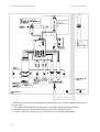
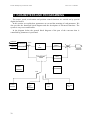
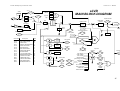
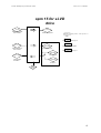
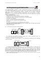
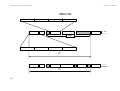
The main block diagram and the diagrams for special functions (operating modes) are
described later in more detail.
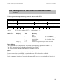
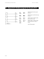
How to associate inputs/outputs to the parameters of the converter is described in the chapter,
The pico-PLC.
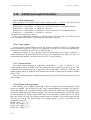
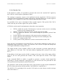
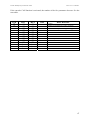
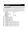
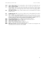
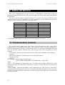
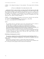
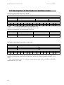
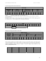
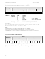
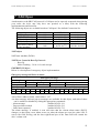
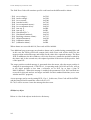
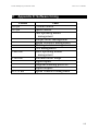
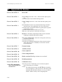
The parameters are divided on the basis of their function in the following way.
From Pr0 to Pr49
From Pr50 to Pr70
From Pr71 to Pr99
From Pr100 to Pr150
From Pr151 to Pr163
From In0 to In127
Main parameters
Position loop
pico-PLC parameters
Operating mode parameters
pico-PLC parameters
pico-PLC instructions
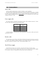
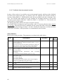
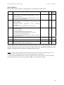
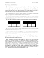
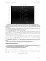
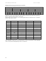
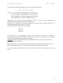
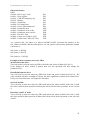
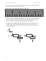
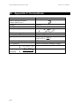
The units of measurement and the main resolutions of the parameters are:
Parameter
type
Speed
Acceleration
Position
Unit
Revolutions/minute
Seconds/1000 revolutions/minute.
4096 steps/revolution
Current
% of the peak current of the converter
Resolution
1
0.001
1/4096 of a
revolution
0.1
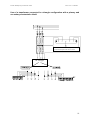
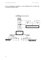
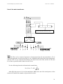
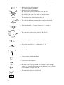
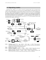
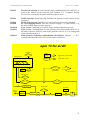
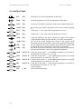
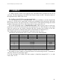
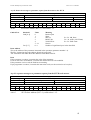
Below we describe how to interpret the symbols used in the block diagrams. The main
block diagram describes graphically how the converter works. Each rectangular block
represents one or more read-write parameters. The rhomboid blocks represent read-only
parameters. You can find other functional blocks in the diagram such as: GREATER THAN,
EQUAL TO, LESS THAN, logical AND/OR. For all these functional blocks, standard
symbols are used. Binary parameters are represented as switches and the position in the
diagram corresponds to the default value.
33