1
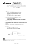
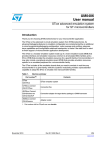
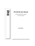
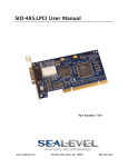
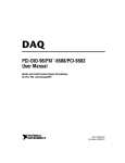
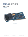
DIO-104.OPTO User Manual
Part Number 3720H
www.sealevel.com
PO Box 830 Liberty, SC 29657
864.843.4343
Table of Contents
INTRODUCTION......................................................................................................................... 1
OTHER SEALEVEL PC104 DIGITAL I/O PRODUCTS ...................................................................... 1
BEFORE YOU GET STARTED................................................................................................. 2
WHAT’S INCLUDED ...................................................................................................................... 2
OPTIONAL ITEMS.......................................................................................................................... 2
CARD SETUP ............................................................................................................................... 3
ADDRESS SELECTION ................................................................................................................... 3
SOFTWARE INSTALLATION .................................................................................................. 4
PHYSICAL INSTALLATION .................................................................................................... 6
PROGRAMMING THE DIO-104.OPTO .................................................................................. 7
PROGRAMMING FOR WINDOWS .................................................................................................... 7
PROGRAMMING FOR LINUX .......................................................................................................... 7
DIGITAL I/O INTERFACE .............................................................................................................. 7
INPUT PORTS ................................................................................................................................ 8
INPUT PIN ASSIGNMENTS (P2) ..................................................................................................... 9
READING THE INPUTS................................................................................................................... 9
ELECTRICAL CHARACTERISTICS .................................................................................... 10
FEATURES .................................................................................................................................. 10
SPECIFICATIONS ......................................................................................................................... 10
EXAMPLE CIRCUITS .............................................................................................................. 11
APPENDIX A - TROUBLESHOOTING ................................................................................. 12
APPENDIX B - HOW TO GET ASSISTANCE ...................................................................... 13
APPENDIX C – SILK SCREEN – 3720H PCB ....................................................................... 14
APPENDIX D - COMPLIANCE NOTICES............................................................................ 15
FEDERAL COMMUNICATIONS COMMISSION STATEMENT ........................................................... 15
WARRANTY............................................................................................................................... 16
© Sealevel Systems, Inc.
SL9019H Revision 7/2006
DIO-104.OPTO User Manual
Introduction
The DIO-104.OPTO is a PC/104 form factor adapter that provides 16 optically
isolated inputs (rated for 10-30V) to allow monitoring of off board switch closures,
relays or for any other general purpose monitoring needs.
The DIO-104.OPTO is designed to be used with a variety of Operating Systems
including Windows 98/NT/ME/2000/XP and DOS. The SeaI/O API (Application
Programmer Interface) included on CD with the DIO-104.OPTO provides a variety
of useful high-level function calls implemented as a Windows dynamic link library
(DLL). In addition to the API, SeaI/O includes sample code and utilities to simplify
software development.
Other Sealevel PC104 Digital I/O Products
PIO-48.PC104
(P/N 3701)
- 48 Channel TTL
DIO-104.REL
(P/N 3710)
- 16 Reed Relay Outputs
DIO-32.104
(P/N 3730)
- 16 Optically Isolated Inputs/16 Reed Relays
© Sealevel Systems, Inc.
-1-
DIO-104.OPTO User Manual
Before You Get Started
What’s Included
The DIO-104.OPTO is shipped with the following items. If any of these items is
missing or damaged please contact Sealevel for replacement.
DIO-104.OPTO Adapter
Sealevel SeaI/O Software CD
Optional Items
Depending upon your application, you are likely to find one or more of the
following items useful for interfacing the DIO-104.OPTO to real-world signals. All
items can be purchased from our website (http://www.sealevel.com) or by calling
(864) 843-4343.
40-Pin IDC to DB-37 Female 8” Ribbon Cable (Part Number CA211)
− For compatibility with other Sealevel digital I/O devices, the CA211
connects to the 40-pin header connector on the DIO-104.OPTO and
provides a DB-37 Female connector.
DB-37 Male to DB-37 Female 6’ Cable - (Part Number CA112)
− This cable extends the DB-37 connector on the DIO-104.OPTO to six
feet and is pinned one-to-one.
DB-37 Male/Female Terminal Block (Part Number TB02-KT)
− Break out serial and digital connectors to 37 screw terminals for easy
field connection. The TB02 terminal block is designed with both DB37 male and female connectors, therefore; it can be used with any
DB-37 board regardless of the board's port gender.
Cable and Terminal Block Kit (Part Number KT101)
− For convenient and easier ordering, the KT101 includes the TB02-KT
terminal block and CA112 cable in a single kit.
© Sealevel Systems, Inc.
-2-
DIO-104.OPTO User Manual
Card Setup
Address Selection
The DIO-104.OPTO occupies 4 consecutive I/O locations. The DIP-switch (S1) is
used to set the base address for these locations. Be careful when selecting the base
address as some selections conflict with existing PC ports. The following table
shows several examples that usually do not cause a conflict. Even though four I/O
addresses are decoded, only the first two are actually used, the other two ports are to
maintain compatibility with existing Sealevel Systems adapters.
Address
100-103
104-107
200-203
280-283
284-287
2EC-2EF
300-303
320-323
388-38B
3A0-3A3
3A4-3A7
Binary
01 0000 00xx
01 0000 01xx
10 0000 00xx
10 1000 00xx
10 1000 01xx
10 1110 11xx
11 0000 00xx
11 0010 00xx
11 1000 10xx
11 1010 00xx
11 1010 01xx
A9
1
On
On
Off
Off
Off
Off
Off
Off
Off
Off
Off
A8
2
Off
Off
On
On
On
On
Off
Off
Off
Off
Off
Switch Settings
A7 A6 A5 A4 A3 A2
3
4
5
6
7
8
On On On On On On
On On On On On Off
On On On On On On
Off On On On On On
Off On On On On Off
Off Off Off On Off Off
On On On On On On
On On Off On On On
Off On On On Off On
Off On Off On On On
Off On Off On On Off
The following illustration shows the correlation between the DIP-switch setting and
the address bits used to determine the base address. In the example below, address
300 is selected as the base address. Address 300 in binary is XX 11 0000 00XX
where X = a non-selectable address bit.
A9
A2
ON
OFF
1 2 3 4 5 6 7 8
Note: Setting the switch ‘On’ or ‘Closed’ corresponds to a ‘0’ in the address, while
leaving it ‘Off’ or ‘Open’ corresponds to a ‘1’.
© Sealevel Systems, Inc.
-3-
DIO-104.OPTO User Manual
Software Installation
Windows 98/ME/NT/2000/XP Installation
Do not install the Adapter in the machine until the software has been fully
installed.
1. Start Windows.
2. Insert the Sealevel Systems CD in to your CD drive.
3. If ‘Auto-Start’ is enabled for this drive the software will automatically
launch. Otherwise, point your browser to the ‘Index.htm’ on the root
directory of the CD
4. Select ‘Install Software’.
5. Select the Part Number for your adapter from the listing.
6. Select ‘Windows 98/NT/ME/2000/XP’. The setup file will automatically
detect the operating environment and install the proper components. Next
(depending on your browser) select the ‘Run this program from its current
location’ or ‘Open’ option. Follow the information presented on the screens
that follow. During setup the user may specify installation directories and
other preferred configurations. This program also adds entries to the system
registry that are necessary for specifying the operating parameters for each
driver. An uninstall option is also available to remove SeaIO files and
registry/INI file entries from the system.
7. If installing in NT, skip to step 16. ‘Windows NT Card Installation’.
8. Go to the “Add New Hardware Wizard” in the Control Panel.
9. When the Wizard asks if you want Windows to search for the new
hardware, choose “No, I want to select the hardware from a list.”
10. Scroll through the list of categorized hardware and select ‘SeaIO Devices’.
If this is the first SeaIO device you may need to select ‘Other Devices’ and
‘Sealevel Systems, Inc.’ instead of ‘SeaIO Devices’.
11. Click “Next”.
12. Select the card model and press “Next”.
13. The Wizard will guide you through a few more informational prompts;
continue to click “Next” until it is completed.
14. Your card’s resource assignments may be adjusted through the Device
Manager (if, for instance, you need to change the I/O port address Windows
assigned when you installed the card).
15. Windows software installation is complete
16. Windows NT Card Installation: After accomplishing steps 1 – 6, bring up
the Control Panel and double-click on the SeaIO Devices icon. To install a
new card, click “Add Port”. Repeat this procedure for as many SeaIO cards
as you wish to install.
© Sealevel Systems, Inc.
-4-
DIO-104.OPTO User Manual
Linux Installation
Note: You MUST have "root" privileges to install the software and drivers.
1. Login as "root".
2. Mount the CDROM by typing:
mount -t iso9660 /dev/hdc /cdrom
Note Your cdrom may not be /dev/hdc it could be /dev/hda, /dev/hdb, /dev/hdd, or if
you have a SCSI drive /dev/sda, /dev/sdb, /dev/sdc, etc. You may mount the
CDROM to any location, the /cdrom is just a common example.
3. Next change to the directory where you mounted the CDROM:
Ex. cd /cdrom/software/SeaIO/Other/linux
Note: The syntax is case sensitive.
4. Copy seaio.tar.gz to your home directory by typing:
cp seaio.tar.gz ~
5. Change to your home directory by typing:
cd
6. Unmount the drive and then Unzip and Untar the drivers and software by
typing:
umount /cdrom
tar -xvzf seaio.tar.gz
7. Change to the seaio directory by typing:
cd seaio
8. Now compile and prepare the drivers for use:
make install
9. Using your favorite text editor, edit the /etc/seaio.conf
10. Within the quote marks, insert
cardtype=0xYourSeaIOcardType io=0xCardBaseAddress
Note: YourSeaIOcardType = Model Number of your SeaIO Card.
CardBaseAddress = What base address you have your SeaIO card addressed at.
11. Save the file and exit your editor.
12. Load the driver by typing:
seaio-load
13. The driver has enabled the card and is ready to use.
To set up Linux to automatically load the driver; refer to a Linux manual concerning
your specific distribution for help.
© Sealevel Systems, Inc.
-5-
DIO-104.OPTO User Manual
Physical Installation
Extreme care should be taken when installing the DIO-104.OPTO to avoid causing
damage to the connectors. After the adapter is installed, connect your I/O cable to
P2. Please note these headers are keyed so that pin 1 of the cable matches pin 1 of
the connector. Refer to Card Setup for information on setting the address before
inserting the DIO-104.OPTO onto the stack.
Do not install the Adapter in the machine until the software has been fully
installed.
1. Turn off power. Disconnect the power cord.
2. Remove the case cover (if applicable).
3. Gently insert the DIO-104.OPTO connector noting proper key orientation of
the expansion connector on a PC/104 compatible card. The DIO-104.OPTO
adapter is keyed per the current PC/104 Specification. This will aid in
preventing the adapter from being inserted incorrectly.
4. Mounting hardware (nylon stand-offs and screws) is provided to ensure a
good mechanical connection. Retain any mounting hardware not used to allow
for future expansion.
5. The cables provided are keyed and can be installed before or after the adapter
is inserted in the stack.
6. Replace the cover.
7. Connect the power cord and power up the machine.
The DIO-104.OPTO is now ready for use.
3rd Party Software Support
Third party software support for many HMI/MMI and other process control software
is included on the product installation CD. For the most up to date information on
third party software support, please visit:
http://www.sealevel.com/thirdpartysoftware.asp
© Sealevel Systems, Inc.
-6-
DIO-104.OPTO User Manual
Programming the DIO-104.OPTO
Sealevel’s SeaI/O software is provided to assist in the development of reliable
applications for the Sealevel Systems family of digital I/O adapters. Included on the
SeaI/O CD are driver functions for use in accessing the I/O as well as helpful
samples and utilities.
Programming for Windows
The SeaI/O API (Application Programmer Interface) provides a variety of useful
high-level function calls implemented in a Windows dynamic link library (DLL).
The API is defined in the help file (Start/Programs/SeaIO/SeaIO Help) under
“Application Programmers Interface”. This help file also includes detailed
information dealing with installation / removal of the software and information
about latency, logic states, and device configuration.
For C language programmers we recommend using the API to access the DIO104.OPTO. If you are programming in Visual Basic, using the ActiveX control
included with SeaI/O is advised.
Samples and Utilities
A variety of sample programs and utilities (both executable and source code) are
included with SeaI/O. Further documentation on these samples can be found by
selecting “Start/Programs/SeaIO/Sample Application Description”. Information
about where the files are physically stored on your disk is also included in this same
file.
Programming for Linux
SeaI/O for Linux consists of two major parts: a kernel module and a library. The
kernel module is a simple IO pass-through device, allowing the library to handle the
more sophisticated functions provided to SeaI/O users. It is provided in a ‘tarball’
format and can easily be compiled and included in the kernel build.
Digital I/O Interface
The DIO-104.OPTO provides four parallel input/output (I/O) ports. The ports are
organized as ports A, B, C, and D. Ports A and B are input ports interfaced to
optically-isolated inputs, while ports C and D decoded but not used. Assuming an
I/O address of 300 Hex the following table shows the Port Addresses.
Base Address Hex Decimal
Mode
Port A Address 300
768
Optically Isolated Input Port
Port B Address 301
769
Port C Address 302
770
Not used
Port D Address 303
771
© Sealevel Systems, Inc.
-7-
DIO-104.OPTO User Manual
Input Ports
Ports A and B are 8 bit input ports connected to optically isolated input sensors.
Each sensor can be used to interface a voltage input and then sense whether the
voltage is on or off. Each sensor is isolated with respect to a common ground from
every other sensor and also isolated with respect to the host PC ground. This means
that signals such as low-level AC voltage, motor servo voltage, and control relay
signals can be ‘sensed’, or read by the PC, without the risk of damage due to ground
loops or ground faults.
Each sensor input pair has a current limiting resistor that is used to limit the input
current to the opto-isolator. The opto-isolator has two ‘back-to-back’ diodes
internally. This allows AC or DC signals to be sensed regardless of polarity. When
the signal is high enough to cause the opto-isolator to turn-on, the output of the optoisolator goes low (0 volts) and the port bit is read as a low logic level (binary 0) by
the PC. When the input signal is too low to turn on the opto-isolator, the output goes
high and the port bit is read by the PC as a high logic level (binary 1).
The input impedance of each isolated input is approximately 3.3K ohms
(factory default). The opto-isolator requires approximately 3mA to turn on. The
maximum input current is 50mA. There are two things to consider when selecting
the input resistor. The first is turn on voltage for the circuit to sense, and second is
the maximum input voltage. Maximum input voltage must not provide too much
power to the input resistor, and must also not overdrive the opto-isolator input
current specification. The following formulas apply:
Turn on Voltage = diode drop + (turn on current) x (resistance) [Ex: 1.1 + (.003) x R]
Input Current = ((input voltage)-1.1V) / (resistor value)
Maximum voltage = 1.1 + square root of (.25(resistor value))
The following table shows common input resistors and the ranges associated with
each.
Input Resistor
Turn-On
Input Range
Max Input
1.8V
1.8 – 7.0V
8.5V
220Ω
2.8V
2.8 – 10.6V
12.9V
560Ω
4.1V
4.1 – 13.8V
16.9V
1KΩ
7.7V
7.7 – 20.0V
24.5V
2.2KΩ
10.0V
10.0 – 24.0V
30.0V
3.3KΩ
15.2V
15.2
–
28.0V
35.0V
4.7KΩ
Note: The turn-off voltage for all resistors is less than 1V.
Max Current
27mA
20mA
15mA
10mA
9mA
7mA
Increasing the input resistor accordingly can increase the maximum input voltage.
Because socketed DIP resistors are utilized, they can easily be replaced with a
different value. Sealevel, if necessary can do this.
Important: The input circuits are not intended for monitoring 120-volt AC circuits.
In addition to being too high a voltage for the circuits, it is dangerous to have that
high a voltage on the card.
© Sealevel Systems, Inc.
-8-
DIO-104.OPTO User Manual
Input Pin Assignments (P2)
Port A Bit P2 DB-37 Port B Bit P2 DB-37
36
18
20
29
0
0
35
37
19
10
34
17
18
28
1
1
33
36
17
9
32
16
16
27
2
2
31
35
15
8
30
15
14
26
3
3
29
34
13
7
28
14
12
25
4
4
27
33
11
6
26
13
10
24
5
5
25
32
9
5
24
12
8
23
6
6
23
31
7
4
22
11
6
22
7
7
21
30
5
3
Ground
+ 12 Volts
+ 5 Volts
4
3
2
1
37
21
2
20
1
19
Reading the Inputs
The inputs are active Low. If no voltage is applied across one of the differential
inputs it returns a one on that bit. If an AC or DC voltage (of sufficient magnitude,
covered above) is applied it returns a zero on that bit.
Function Available
R
R
R = Read
© Sealevel Systems, Inc.
Port
A
B
Address Hex
Base + 0
Base + 1
-9-
DIO-104.OPTO User Manual
Electrical Characteristics
Features
2 eight bit input ports
Selectable I/O port addressing from 100H - 3FFH
Multiple adapters can reside in same computer
All address, data and control signals are TTL compatible
Specifications
Input Ports
Turn On Current:
Isolator Diode Drop:
Resistor Power Max:
Maximum Input Range:
3mA
1.1 VDC
.25 W
10 – 30 VDC/VAC
Temperature Range
Operating:
Storage:
0°C – 70°C
-50°C – 105°C
Power Requirements
+5VDC @ 125mA
+12VDC (Optional)
Physical Dimensions
PCB Length:
PCB Height:
3.6” (9.0 cm)
3.8” (9.6 cm)
Manufacturing
All Sealevel Systems Printed Circuit boards are built to UL 94V0 rating and are
100% electrically tested. These printed circuit boards are solder mask over bare
copper or solder mask over tin nickel.
© Sealevel Systems, Inc.
- 10 -
DIO-104.OPTO User Manual
Example Circuits
Input Circuit
© Sealevel Systems, Inc.
- 11 -
DIO-104.OPTO User Manual
Appendix A - Troubleshooting
Following these simple steps can eliminate most common problems.
1. Install software first. After installing the software then proceed to adding the
hardware. This places the required installation files in the correct locations.
2. Read this manual thoroughly before attempting to install the adapter in your
system.
3. Use Device Manager under Windows to verify proper installation.
4. Use the SeaIO Control Panel applet or the Device Manager’s property page for
card identification and configuration.
5. The following are known I/O conflicts:
• The 278 and 378 settings may conflict with your printer I/O adapter.
• 3B0 cannot be used if a Monochrome adapter is installed.
• 3F8-3FF is typically reserved for COM1.
• 2F8-2FF is typically reserved for COM2.
• 3E8-3EF is typically reserved for COM3.
• 2E8-2EF is typically reserved for COM4.
6. If these steps do not solve your problem, please call Sealevel Systems’ Technical
Support, (864) 843-4343. Our technical support is free and available from
8:00AM-5:00PM Eastern Time Monday through Friday. For email support
contact [email protected].
© Sealevel Systems, Inc.
- 12 -
DIO-104.OPTO User Manual
Appendix B - How To Get Assistance
Begin by reading through the Trouble Shooting Guide in Appendix A. If assistance
is still needed please see below.
When calling for technical assistance, please have your user manual and current
adapter settings. If possible, please have the adapter installed in a computer ready to
run diagnostics.
Sealevel Systems provides an FAQ section on its web site. Please refer to this to
answer many common questions. This section can be found at
http://www.sealevel.com/faq.asp
Sealevel Systems maintains a Home page on the Internet. Our home page address is
http://www.sealevel.com. The latest software updates, and newest manuals are
available via our FTP site that can be accessed from our home page.
Technical support is available Monday to Friday from 8:00 a.m. to 5:00 p.m. eastern
time. Technical support can be reached at (864) 843-4343.
RETURN AUTHORIZATION MUST BE OBTAINED FROM SEALEVEL
SYSTEMS BEFORE RETURNED MERCHANDISE WILL BE ACCEPTED.
AUTHORIZATION CAN BE OBTAINED BY CALLING SEALEVEL
SYSTEMS AND REQUESTING A RETURN MERCHANDISE
AUTHORIZATION (RMA) NUMBER.
© Sealevel Systems, Inc.
- 13 -
DIO-104.OPTO User Manual
Appendix C – Silk Screen – 3720H PCB
© Sealevel Systems, Inc.
- 14 -
DIO-104.OPTO User Manual
Appendix D - Compliance Notices
Federal Communications Commission Statement
FCC - This equipment has been tested and found to comply with the limits for Class
A digital device, pursuant to Part 15 of the FCC Rules. These limits are designed to
provide reasonable protection against harmful interference when the equipment is
operated in a commercial environment. This equipment generates, uses, and can
radiate radio frequency energy and, if not installed and used in accordance with the
instruction manual, may cause harmful interference to radio communications.
Operation of this equipment in a residential area is likely to cause harmful
interference in such case the user will be required to correct the interference at the
users expense.
EMC Directive Statement
Products bearing the CE Label fulfill the requirements of the EMC directive
(89/336/EEC) and of the low-voltage directive (73/23/EEC) issued by the European
Commission.
To obey these directives, the following European standards must be met:
EN55022 Class A - “Limits and methods of measurement of radio interference
characteristics of information technology equipment”
EN55024 – “Information technology equipment Immunity characteristics Limits and
methods of measurement”.
EN60950 (IEC950) - “Safety of information technology equipment, including
electrical business equipment”
Warning
This is a Class A Product. In a domestic environment, this product may cause
radio interference in which case the user may be required to take adequate
measures to prevent or correct the interference.
Always use cabling provided with this product if possible. If no cable is provided or
if an alternate cable is required, use high quality shielded cabling to maintain
compliance with FCC/EMC directives.
© Sealevel Systems, Inc.
- 15 -
DIO-104.OPTO User Manual
Warranty
Sealevel's commitment to providing the best I/O solutions is reflected in the Lifetime
Warranty that is standard on all Sealevel manufactured products. We are able to
offer this warranty due to our control of manufacturing quality and the historically
high reliability of our products in the field. Sealevel products are designed and
manufactured at its Liberty, South Carolina facility, allowing direct control over
product development, production, burn-in and testing.
Sealevel Systems, Inc. (hereafter "Sealevel") warrants that the Product shall conform
to and perform in accordance with published technical specifications and shall be
free of defects in materials and workmanship for life. In the event of failure,
Sealevel will repair or replace the product at Sealevel's sole discretion. Failures
resulting from misapplication or misuse of the Product, failure to adhere to any
specifications or instructions, or failure resulting from neglect or abuse are not
covered under this warranty.
Warranty service is obtained by delivering the Product to Sealevel and providing
proof of purchase. Return authorization must be obtained from Sealevel Systems
before returned merchandise will be accepted. Authorization is obtained by
calling Sealevel Systems and requesting a Return Merchandise Authorization
(RMA) number. The Customer agrees to insure the Product or assume the risk of
loss or damage in transit, to prepay shipping charges to Sealevel, and to use the
original shipping container or equivalent. Warranty is valid only for original
purchaser and is not transferable.
Sealevel Systems assumes no liability for any damages, lost profits, lost savings or
any other incidental or consequential damage resulting from the use, misuse of, or
inability to use this product. Sealevel Systems will not be liable for any claim made
by any other related party.
This warranty applies to Sealevel manufactured Product. Product purchased through
Sealevel but manufactured by a third party will retain the original manufacturer's
warranty.
Sealevel Systems, Incorporated
2779 Greenville Highway
P.O. Box 830
Liberty, SC 24857 USA
(864) 843-4343
FAX: (864) 843-3067
www.sealevel.com
email: [email protected]
Technical Support is available Monday - Friday from 8 a.m. to 5 p.m. Eastern time
Trademarks
Sealevel Systems, Incorporated acknowledges that all trademarks referenced in this
manual are the service mark, trademark, or registered trademark of the respective
company.
© Sealevel Systems, Inc.
- 16 -
DIO-104.OPTO User Manual