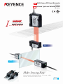
1
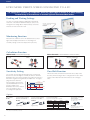
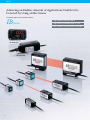
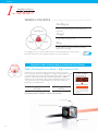
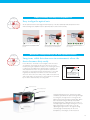
NEW
Multi-Purpose CCD Laser Micrometer
IG Series
NEW
Thrubeam Type Laser Detection Sensor
IB Series
I-
NEW LINEUP
Intelligent Sensor
SERIES
IG Series
IB Series
Make Sensing Easy:
F R O M S I M P L E D I F F E R E N T I AT I O N TO H I G H S P E E D,
H I G H LY A C C U R AT E D E T E C T I O N
Low-cost
High
Performance
CHOOSE KEYENCE FOR ALL THRUBEAM TYPES
IB S
eries
Photoelectric
sensor
Detection of presence/absence
Low cost
Thrubeam Type Laser Detection Sensor IB Series
Light volume differentiated with high-accuracy
Light-receiving element
PD
Through high-accuracy differentiation of the volume of light received, the photoelectric sensor allows a
multitude of previously impossible applications to be achieved.
A PD (Photo Diode) is used within the light-receiving element. Even very small changes in received light intensity are sensed, making this sensor
incredibly versatile.
❚ Main applications
Detecting cap tightness
Differentiation of different films
Determining chip gradient
High-Accuracy Differentiation Made Easy
without being Influenced by the Target
2
Liquid turbidity
Thrubeam
measuring
instruments
IG S
eries
High-accuracy measurements
High end
Multi-Purpose CCD Laser Micrometer IG Series
High-accuracy differentiation using edge position
Light-receiving element
CCD
Achieving high-accuracy differentiation without being influenced by the total light volume
A CCD (Charge Coupled Device) is used in the light-receiving element. High-accuracy differentiation is achieved by capturing the edge of the
thrubeam laser light rather than the volume of received light.
❚ Main applications
Transparent glass
edge detection
Outer diameter
high-accuracy differentiation
I-
Sheet edge control
Roller gap measurement
Intelligent
I
Intelligent Sensor
SERIES
SERIES
Tough
Easy
3
IB Series Applications
❚ Supports everything from simple differentiation to high-accuracy detection
Industrial application examples
Liquid Crystal Industry
Electronic Industry
Detection of presence/absence
of liquid crystal glass
Detection of chip components
IB
Within the various manufacturing processes of liquid crystal, the presence
or absence of a glass plate is detected during transportation. As the light
volume can be differentiated with high-accuracy, stable detection is
possible.
This device definitively detects the chip gradient and/or the presence of a
chip on even minute targets during the mounting process. Furthermore, as
the sampling occurs at 80 µs, detections on high-speed lines are also
possible.
Electric Industry
Metal Industry
Printer paper feed orientation
detection
Differentiation of different metal
shafts
IB
By sensing two locations simultaneously, the device detects the orientation
of the paper feed and/or the skew angle during transportation. Continuous
measurement is possible with the small type head and high-speed
sampling.
IB
Detects differences in various shafts within metal workings or during the
assembly process. By using the included Hold function, this can be
determined without stopping the target.
Plastics Industry
Factories
Differentiation of different
films
Turbidity detection of
factory waste water
IB
By sensing the thrubeam volume of laser light, the device definitively
captures any differences in the transparent film. Furthermore, by aligning
multiple devices along the width, continuous detection of uneven coating
over multiple points is possible.
IB
By sensing the thrubeam volume of laser light through glass, the turbidity of
factory waste water can be determined. Furthermore, judgment values can
be set between 0 and 100%.
Food and
Pharmaceutical
Industry
Food and
Pharmaceutical
Industry
Bottle-neck diameter
judgments and detection
of cap tightness
Detecting the liquid level
of test tubes
IB
Detects the diameter and cap tightness when adding the caps onto the
bottles. Due to high-speed sampling, detection can be conducted on the
conveyer without stopping the target.
4
IB
IB
By sensing thrubeam volumes of the laser light, the liquid level can be
detected with high accuracy. Furthermore, by using a compact head the
device can be positioned in even the narrowest of spaces.
IG Series Applications
Semi-conductor Industry
Wafer notch detection
IG
Liquid Crystal
Industry
Position determination of
liquid crystal glass
IG
Detects the notch position of a wafer with high accuracy. The device
exhibits a repeat accuracy of 5 μm and the differential ability that is top of
its class.
Electrical Industry
Edge control of a lithiumion electrode sheet
IG
Conducts edge control during the winding process of electrode sheets,
achieving uniform rolling.
Y
Conducts high-accuracy transport position determination of liquid crystal
glass. Incorporating a new algorithm, stable detection of even transparent
materials is possible.
Electric Cable
Industry
External diameter
differentiation during
coating extrusion processes
IG
Differentiates the coating line diameter immediately after extrusion. By
calculating the roundness differentiation between X-Y, this can be
conducted simultaneously without external software.
Metal Industry
Metal Industry
Target placement
confirmation
Internal diameter
differentiation of punch
press materials
IG
Differentiates the positioning of the target during pressing. The device is
IP-67 rated, with the ability to withstand use in unfavorable environments
over a long period of time.
Plastics Industry
Edge control of a
transparent sheet
IG
Conducts the edge control of film during winding processes, and achieves a
uniform roll. The level of shielded light can be changed at will, allowing for
the high-accuracy determination of thin film.
X
IG
Measures the internal diameter or gaps of pressed parts. By using the
various Hold functions you can also measure the maximum internal
diameter.
Iron and Steel
Industry
Roll gap measurement
IG
Monitors the gap of thin plate cold rolling. Mounting in narrow spaces is
also possible thanks to a compact head.
5
IG Series
Achieving the Best Stability
Multi-Purpose CCD Laser Micrometer
IG S
eries
Parallel light lens
Reflecting mirror
28 mm
Multi-wavelength
laser
10 mm
28mm type
IG-028
Repeatability of 5 μm
10mm type
IG-010
Linearity of ± 0.1% (IG-028)
New function: Position Monitor
Wide Variety of Application Modes
6
Edge Control
Mode
Outer Diameter
Measurement Mode
The distance from the end of the measurement range to
the edge of a target is measured.
The outer diameter or width of a target is measured.
L-CCD
L-CCD
Position
monitor
POSITION
MONITOR
I-DSP
POSITION MONITOR
Measurements are performed
with up to 28,000 optical axes
(IG-028), each of which monitors
the amount of light received.
Large Distance between the Transmitter and Receiver
IG-028
Max. 1500 mm
IG-010
Max. 1000 mm
Panel mount type
IG-1500/1550
DIN-rail mount type
IG-1000/1050
Edge Detection of
Transparent Targets
Inner Diameter/Gap
Measurement Mode
Measures a transparent edge like glass
The inner diameter of a target or a gap between targets is
measured.
7
IG Series
I-
Intelligent Sensor
SERIES
THREE CONCEPTS
Intelligent
High accuracy was achieved by using the technology and
functions developed for high-accuracy measuring
instruments.
Intelligent
Tough
I
Developed for use in harsh environments, the I Series was
designed with a strong structure.
SERIES
Tough
Easy
Easy
Excellent usability makes it possible to quickly and easily
perform stable measurements without any difficult
adjustments and settings.
The intelligent I-Series consists of a high-accuracy sensor lineup that realises low-cost high
performance with only the most advanced functions for on-site operations.
High stability and measurement accuracy are achieved
with the newly developed optical system
Intelligent
I
Tough
SERIES
Easy
Multi-Wavelength Laser + I-DSP
With conventional lasers, the transmission spot produces a patchy pattern
(as shown in the figure to the right). This is a laser-specific interference
problem caused by the laser having a single wavelength. The IG Series
sensor overcomes this problem by using a multi-wavelength laser. Because
shadows are formed on the CCD more clearly, the sensor remains highly
stable, even with targets that are conventionally
difficult to detect (e.g. transparent objects). With
the I-DSP (a parallel computing chip)
incorporated in the receiver, the sensor can
perform data processing at high speed,
reducing noise to a minimum.
Best in its class
S P OT I M AG E
Single-wavelength laser
(conventional laser sensor)
A patchy pattern appears.
Multi-wavelength laser (IG)
Due to the multi-wavelength
laser used, the beam pattern
has a more uniform intensity
distribution.
Best in its class
Repeatability of 5 µm
Linearity of ±0.1%
STABLE DETECTION OF TRANSPARENT
& MESH TARGETS
The L-CCD makes it possible to detect a target based on its
position. Edge control and positioning of transparent and
mesh targets can be performed stably.
Transparent target
8
Low-cost
High
Performance
Mesh target
Extremely easy to use due to the built-in position monitor
Intelligent
I
Tough
SERIES
Easy
Determining the Part of a Target
to be Measured
Red: Indicates
the received light
position
The position monitor on the IG Series sensors makes it
possible to visually check how a target is detected. The
user can prevent mounting or setting errors by observing
the red lights that indicate the received light position and
the green lights that indicate the measurement position.
Green:
Indicates the
measurement
position
Easier Optical Axis Alignment
The position monitor makes it easier to align the optical
axis. Easily perform optical axis alignment by adjusting
the sensor head so that all of the position monitor lights
turn red.
Optical axis alignment in
progress
Easy to maintain thanks to excellent environment resistance
Intelligent
I
Tough
SERIES
Optical axis alignment
complete
Key Point: Less Sensitive to Dirt
Easy
L-CCD
Binarization
level
L-CCD
Binarization
level
28
Because it uses an L-CCD, the IG Series is less sensitive
to materials such as dirt than a sensor that uses a
photodiode (PD) as the light-receiving element.
0
Received light level
28
If the sensor
gets dirty...
0
Received light level
Although dirt reduces the total amount of light
received, the measurement position is the same.
The shadow of a target is shown.
Edge Check Function
The user can check whether a measurement is performed
correctly by verifying the number of edges in the field of
view.
Example
- Prevent dust or oil from adhering to the measurement unit,
which can cause an abnormal measurement value.
- Detect the intrusion of a different type of target.
- Check that a measurement target falls within the measurement range.
Flexible Free-Cut Cable
The sensor head cable is a robot cable that withstands
repeated bending. The cable can be used safely in a
position requiring repeated motion.
No break in the cable after
20 million bends (typical)
90°
Load (W): 250 g
Bending radius: R50 mm
Rate: 30 bends/minute
R
(One bend is a cycle whereby the
cable is bent from left to right and
then from right to left.)
Free Cut!
L
IP67 Protection
The enclosure satisfies the IP67 rating based on the IEC
standards and remains watertight even after being held at
a depth of one metre for 30 minutes. The enclosure is
resistant to adverse environments and offers long-term
durability.
9
IG Series
EVEN MORE USEFUL WHEN CONNECTED TO A PC
The configuration software, IG Configurator, allows for a wide range of settings to be made including
the monitoring of the waveforms of received light and the measurement modes.
Reading and Writing Settings
The user can enter all settings including the measurement
modes into a PC and then transfer them to the sensor. The
management of setting data is simple and very convenient
when two or more sensors are used.
RS-232C
communication unit
DL-RS1A
Monitoring Function
Measurement conditions such as the waveforms of received
light can be displayed in real time. The mounting and
sensitivity settings can also be adjusted more precisely.
Calculation Function
Addition mode (if a measurement target is large)
SETTING EXAMPLE 1
(length)
Subtraction mode (to measure the difference in level or inclination)
SETTING EXAMPLE 2
(width)
SETTING EXAMPLE 1
(inclination)
SETTING EXAMPLE 2
(difference in thickness)
Zero Shift Function
The set value used to judge whether light enters or is blocked,
based on the amount of light received by the CCD, is called the
binarization level. The amount of light received when the reference
waveform is registered is regarded as the 100% level. The light is
judged to be blocked if the
100%
Can be
amount of light is less than the
changed freely
specified binarization level. The
IG Series initially sets a
25%
binarization level of 25% and the
0%
user can change the level
CCD position
according to the application.
This function shifts an internal measurement value to 0 (to offset
the value). When the target value is changed, this function can be
used to shift an internal measurement value to the new target
value.
Received light level
Sensitivity Setting
Option
PC software 1.
IG-H1
Sensor head mounting
brackets for IG-010 2.
Sensor head mounting
brackets for IG-028 2.
IG-TB01
IG-TB02
Approx. 50 g
1. The DL-RS1A communication unit is required.
4. Two cables are included with a sensor head.
10
Sensor head cables 3.
Connected connector
with indicator
Select when a longer cable is required.
Cable length
Approx. 40 g
2. The screws for connecting the sensor head and bracket are included.
Model
Weight
2 m 4.
OP-87056
Approx. 80g
5m
OP-87057 Approx. 190g
Piece
10 m
1 cable
OP-87058 Approx. 360g included
20 m
OP-87059 Approx. 680g
This connector is required if
the cable is cut.
OP-84338
Connector used to connect to
a display unit (2 pcs.)
3. The cable is common to the transmitter and receiver, and can be used with either of them.
Specifications
Sensor heads
Model
IG-010
IG-028
Appearance
Operation principle
Light source
FDA (CDRH) Part 1040.10
IEC60825-1
Mounting distance
Measurement range
Sampling rate
Minimum detectable
object 2.
CCD method
Visible light semiconductor laser (Wavelength:660 nm)
Class 1 1.
Class 1
0 to 1000 mm
10 mm
High sensitivity mode
Standard mode
Repeatability 3.
Linearity 4.
Temperature characteristics 5.
Transmitter
Operation
indicator
Receiver
Enclosure rating
Ambient temperature
Environment
Ambient humidity
resistance
Ambient light 6.
Vibration
Case
Material
Lens cover
Cable
Supplied item
Weight (including supplied items)
0 to 1500 mm
28 mm
980 µs (When the number of times for averaging is set to [hsp]: 490 µs)
ø0.1 mm (Setting distance: 100 mm)
ø0.2 mm (Setting distance: 40 mm or less),
ø0.2 mm (Setting distance: 50mm or less),
ø0.5 mm (Setting distance: 500 mm)
ø0.5 mm (Setting distance: 500 mm)
5 µm (Setting distance: 100 mm)
5 µm (Setting distance: 100 mm)
10 µm (Setting distance: 500 mm)
10 µm (Setting distance: 500 mm)
80 µm (Setting distance: 1000 mm)
80 µm (Setting distance: 1000 mm)
140 µm (Setting distance: 1500 mm )
±0.28 % of F.S. (±28 µm)
±0.1 % of F.S. (±28 µm)
±0.03 % of F.S./°C (±3 µm/°C)
±0.01 % of F.S./°C (±3 µm/°C)
Optical axis alignment indicator: Green LED / Power indicator: Green LED
Optical axis alignment indicator: Green LED / Position monitor: Dual bar LED (Red, Green)
IP67
-10 to +45°C (No freezing)
35 to 85% RH (No condensation)
Incandescent lamp: 5000 lux Sunlight: 5000 lux
10 to 55 Hz Double amplitude 1.5 mm XYZ each axis: 2 hours
Zinc die-cast (Lower case), PBT (Upper case), Polyarylate (PAR) (Display part), SUS304 (Metallic part)
Glass
PVC
Transmitter × 1, Receiver × 1, Sensor head cables (2 m) × 2
Approx. 380 g
Approx. 500 g
1. The classification for FDA (CDRH) is implemented based on IEC60825-1 in accordance with the requirements of Laser Notice No.50.
2. When the measurement target object is measured at the centre position of the setting distance.
When the measurement mode is set to the glass edge mode, a glass edge of C0.1 mm or more can be detected (Setting distance: 500 mm).
3. When the light is shielded by half at the centre position of the setting distance. Vibration width when the average number of times is set to 16 and sampling is performed for 30 seconds.
(When the analogue output is used, the margin of error of analogue output is added.)
4. When the setting distance is 100 mm and light is shielded at 50 mm position from the receiver. Margin of error to the ideal line.
5. When the setting distance is 100 mm and light is shielded by half at 50 mm position from the receiver.
6. Excluding when the average number of times is set to [hsp].
Display unit (amplifier)
Model
IG-1000
IG-1050
IG-1500
IG-1550
Appearance
Amplifier type
Main unit/Expansion unit
Analogue output
Power supply voltage
Power consumption 4.
(including analogue current
output)
DIN rail mount
Normal
Power saving function (HALF)
Power saving function (ALL)
Digital display method
Display range
Display resolution
Judgement output (selectable
between NPN and PNP)
Response time
(judgement output)
Edge check output (selectable
between NPN and PNP)
Output
Analogue output
(selectable among ±5V,
1-5 V, 0-5 V, 4-20 mA)
Input
Environment resistance
Material
Supplied item
Weight (including supplied items)
Panel mount
Expansion unit
Main unit
Expansion unit
No
Yes
No
10-30 VDC, Ripple (P-P): 10% included, Class 2 or LPS
2700 mW or less (at 30 V: 90 mA or less)
2880 mW or less (at 30 V: 96 mA or less)
2300 mW (at 30 V: 77 mA or less)
2200 mW (at 30 V: 74 mA or less)
Dual 7-seg display / Upper level: Red/Green, 2 colours, 5 digits / Lower level: Green, 5 digits
Dual 7-seg display / Upper level: Red, 5 digits / Lower level: Green, 5 digits
-99.999 to +99.999, -99.99 to +99.99, -99.9 to +99.9, -99 to +99 (selectable)
1 µm, 10 µm, 100 µm , 1000 µm(selectable )
Main unit
Yes
Gain input
Reset input
Timing input
Zero shift input
Bank A input/Bank B input
Laser emission stop input
Ambient temperature
Ambient humidity
Vibration
Pollution degree
NPN (PNP) open collector x3ch, 30 VDC (Power supply voltage) or less, residual voltage 1 V (2 V) or less, N.O./N.C. selectable Max. 50 mA/ch 1.
1.96 to 4031.72 ms 2.
NPN (PNP) open collector x1ch, 30 VDC (Power supply voltage) or less, residual voltage 1 V (2 V) or less, N.O./N.C. selectable Max. 50 mA, 1. response time 20 ms
Output range
Output resistance
Maximum load resistance
Repetition accuracy
Display accuracy
Temperature characteristics
Update cycle
Response time
Time constant 3.
Voltage output
Current output
±5 V (full scale 10 V)
4-20 mA (full scale 16 mA)
100 Ω
350 Ω
±1 mV
±1.5 µA
±0.05 % of F.S.
±0.25 % of F.S.
±0.005 % of F.S./°C
±0.01% of F.S./°C
Same as sensor head sampling cycle
Same as Response time (judgement output)
10 µs (90 % response)
30 µs (90 % response)
Input time: 20 ms or more, Response delay time: 120 ms or less (Nonvolatile memory (EEPROM) 1.5 s or less)
Input time: 20 ms or more, Response delay time: 20 ms or less
Input time: 2 ms or more, Response delay time: 2 ms or less
Input time: 20 ms or more, Response delay time: 20 ms or less
Input time: 20 ms or more, Response delay time: 20 ms or less 2.
Input time: 2 ms or more, Response delay time: 2 ms or less
-10 to +50°C (No freezing)
35 to 85%RH (No condensation)
10 to 55 Hz Double amplitude 1.5 mm XYZ each axis: 2 hours
2
Case/Front sheet: Polycarbonate, Key top: Polyacetal, Cable: PVC
Main body × 1, Panel mounting bracket × 1, Front protection cover × 1, Power
supply and input/output cable (2 m) × 1,
Main body × 1, Instruction manual × 1 (only for main unit)
Expansion cable (50 mm) × 1 (only for expansion unit),
Instruction manual × 1 (only for main unit)
Approx. 150 g
Approx. 140 g
Approx. 170 g
Approx. 165 g
1. When expansion units are added: Max. 20 mA/ch
2. For more details, refer to the User’s Manual.
3. Delay time that occurs from the analogue output circuit after the judgment is output.
4. When adding an expansion unit, the consumed electrical power is equal to the total value of the consumed electrical power of all amplifiers.
11
IB Series
Achieving an Endless Amount of Applications Unable to be
Detected by Using a Fibre Sensor
Thrubeam Type Laser Detection Sensor
IB S
High-speed sampling of 80 µs
eries
High-accuracy differentiation of 5 µm
New function: Auto adjustment included
Panel mount type
IB-1500/1550
DIN-rail mount type
IB-1000/1050
IB-30
IB-10
IB-05
IB-01
12
1 device, 3 roles. 3 step output of
presence and size
❚ Photoelectric sensor
❚ Digital laser sensor
3 devices are required each for
presence/absence, height and timing
detections
All detections conducted using a single device
As the position changes, the
thrubeam light volume changes
Regardless of position, the thrubeam light volume
remains the same
Detection is not possible when
strayed off the linear optical axis
Definitive detection in a wide detection area
Does not stabilise due to the subtle
difference in thrubeam light volume
Definitive determination of even the most minute
thrubeam light volume difference
Sensitivity changes according to the
influence of dirt, etc
Dirt is eliminated using the Light intensity correction
function
Upper/lower output-equipped as standard. Not only
presence/absence is detected, but size judgments can also
be conducted using this single device. A timing sensor is also
not required due to the presence of the Auto timing function.
Not influenced by passage position
According to the parallel laser light, no matter where the
target is positioned, the judgment values will remain the
same. This makes high-accuracy differentiation possible
anywhere on the detection area.
No concern of position
misalignment even in wide areas
As the maximum width of the optical axis is 30 mm, stable
detection is possible even if the target is shaking.
High-accuracy detection even in
transparent bodies
In addition to detecting the presence of transparent targets,
detections such as those of single/double transparent films,
density differentiation, and the turbidity of liquids is also
possible. Furthermore, using the percentage display function
the thrubeam rate judgment is also possible.
Not affected by dirt or temperature
changes
By incorporating a Light intensity correction function, the
numerical margin of error caused by aging variation can be
cancelled. Possible to always achieve stable, high-accuracy
judgments.
13
IB Series
I-
Intelligent Sensor
SERIES
THREE CONCEPTS
Intelligent
High accuracy was achieved by using the technology and
functions developed for high-accuracy measuring
instruments.
Intelligent
Tough
I
Developed for use in harsh environments, the I Series was
designed with a strong structure.
SERIES
Tough
Easy
Easy
Excellent usability makes it possible to quickly and easily
perform stable measurements without any difficult
adjustments and settings.
The intelligent I-Series consists of a high-accuracy sensor lineup that realises low-cost high
performance with only the most advanced functions for on-site operations.
Adopting the newly developed optical system used in the IG Series
Intelligent
Multi-Wavelength Laser Beam + High-sensitivity PD
I
Tough
SERIES
Low-cost
High
Performance
Easy
Normal lasers are single wavelength, therefore due to friction, the pattern
becomes patchy, as shown in the diagram on the right. This problem is rectified
in the IB Series by utilising laser light with multiple wavelengths. Targets with a
high level of difficulty can still be detected with a high degree of stability.
Furthermore, by incorporating a high-sensitivity PD within the light receiving
section data can be processed at high speeds, reducing the extraneous
fluctuations to the absolute limit.
S P OT I M AG E
Single-wavelength laser
(conventional laser sensor)
A patchy pattern appears.
Multi-wavelength laser (IB)
High-accuracy differentiation
of 5 µm
Ultra-long distance
of 2 m
Mechanism behind stable detection
Due to the multi-wavelength
laser used, the beam pattern
has a more uniform intensity
distribution.
Protective glass
Light-receiving element (high-sensitivity PD)
Light-receiving lens
14
Simple positioning according to the alignment LED
Intelligent
Easy to align the optical axis
I
Tough
SERIES
Easy
As the optical axis of the laser align, the flash frequency of the laser transmitter indicator quickens. Even
without looking at the amplifier unit, the optimum position can be achieved easily.
If the optical axis is not aligned the LED
turns off
I
Tough
High-speed flashing when the optical
axis is aligned
Maintenance-saving according to the Auto adjustment function
Intelligent
SERIES
When the optical axis begins to align, the
flashing frequency of the LED quickens
Easy
Long-term, stable detection even in environments where the
device becomes dirty easily
In the IB Series, should the received light volume decrease
according to such things as dirt on the front of the sensor
head, by using the adjustment input, the received light volume
is adjusted to standard values during input. In addition, the
Auto adjustment function recognises that this adjustment
input has no measurement target, and therefore is executed
regularly automatically. Even when used in environments
where the device becomes dirty easily, stable measurements
and a high degree of maintenance-saving has been achieved
by the device automatically correcting itself.
Display value
Auto adjustment function ON
100%
90%
Auto adjustment
function OFF
Automatically adjusts
the received light volume
to the standard value
0%
Time progressed
Transmission lens
Semi-conductor laser
Alignment LED
Protective glass
Using the transmission lens, after the laser light
emitted as a parallel beam passes through the light
receiving lens, the light is then converged to the
light-receiving element (high-sensitivity PD). When
the measurement target interrupts this parallel
beam, this beam is in proportion to the volume of
interrupted light and the light entering the received
light element reduces. When this occurs, by
capturing the light volume in the light-receiving
element (high-sensitivity PD), the size and
transparency of the target can be measured.
15
IB Series
Specifications
Sensor head
Model
IB-01
IB-05
IB-10
IB-30
Appearance
Light source
Visible semiconductor laser Wavelength: 660 nm
Class 1 (IEC60825-1, FDA (CDRH) Part1040.10 1.)
0 to 300 mm
Laser Class
Mounting distance
0 to 2000 mm
Ø1 mm
(Installation distance 0 to 300 mm)
Ø1 to 2.5 mm (Installation distance
300 to 2000 mm)
Measurement range
5 mm
10 mm
30 mm
Ø0.05 mm
Ø0.1 mm
Ø0.2 mm
5 µm
5 µm
10 µm
Sampling rate
12,500 times/sec. (80 µs)
Ø8 µm
(Installation distance 0 to 300 mm)
Ø8 to 50 µm
(Installation distance 300 to 2000 mm)
Minimum
detectable object 2.
5 µm
(distance 0 to 300 mm)
±0.2% of F.S./°C
Repeatability 3.
Temperature characteristics 4.
Operation indicator
Ambient luminance
Environmental resistance
Material
Ambient temperature
Ambient humidity
Vibration
Case
Lens cover
Cable
Weight
±0.1% of F.S./°C (±5 µm)
±0.1% of F.S./°C (±10 µm)
±0.1% of F.S./°C (±30 µm)
Laser emission warning indicator: green LED
Incandescent lamp: 5000 lux
Incandescent lamp: 10000 lux
Solar light: 5000 lux
Solar light: 10000 lux
0 to +50°C (no freezing)
35 to 85%RH (no condensation)
10 to 55 Hz Double amplitude 1.5 mm XYZ each axis: 2 hours
Galvanized die cast
Glass
PVC (2 m)
Approx. 180 g
Approx. 220 g
Approx. 510 g
Incandescent lamp: 5000 lux
Solar light: 10000 lux
0 to +40°C (no freezing)
PBT
Approx. 140 g
1. The classification for FDA (CDRH) is implemented based on IEC60825-1 in accordance with the requirements of Laser Notice No.50.
2. Value when measuring the target (white diffuse object) at the middle of the transmitter and receiver position, and at the centre of the measurement range.
3. When distance between transmitter and receiver is set to 300 mm, and light is half-shielded at a position 150 mm from receiver.
Deflection width (±2σ) when sampled for 30 seconds with an average number of times set to 64 times.
4. When distance between transmitter and receiver is set to 100 mm and full light is received.
Amplifier unit
Model
IB-1000
IB-1500
IB-1050
Panel mount
DIN rail mount
IB-1550
Appearance
Amplifier type
Main unit/Expansion unit
Head compatibility
DIN rail mount
Main unit
Yes
0.01%, 0.1%, 1% (switchable)
–99.999 to 99.999, –99.99 to 99.99, –99.9 to 99.9, –99 to 99 (switchable)
Display resolution
Display range
Digital display method
Display
Operation indicator
Analogue voltage output 1.
Analogue current output 1.
Control
input 2.
Control
output 3.
Power supply
Environmental resistance
Material
Weight (including supplied items)
Dual 7-segment display
Upper level:5 red digits
Lower level: 5 green digits
Dual 7-segment display
Upper level:2-colour (green/red) 5
digits
Lower level: 5 green digits
Power consumption 4.
Ambient temperature
Ambient humidity
Vibration
Pollution degree
Dual 7-segment display
Upper level: 2-colour (green/red) 5 digits
Lower level: 5 green digits
Judgment indicator: 2-colour (green/red) LED (HI, GO, LO),
Bank indicator: Green LED x 4,
Laser emission warning indicator: Green LED,
Others: Green LED x 8, red LED x 3
No
Non-voltage input
Open collector (NPN/PNP switchable, N.O./N.C. switchable)
10 to 30 VDC, including ripple (P-P) 10% Class 2 or LPS
Supplied from main unit
1950 mW or less
2100 mW or less
1950 mW or less
2100 mW or less
(at 30 V, 65 mA max.)
(at 30 V, 70 mA max.)
(at 30 V, 65 mA max.)
(at 30 V, 70 mA max.)
-10 to +50°C (No freezing)
35 to 85% RH (No condensation)
10 to 55 Hz Double amplitude 1.5 mm XYZ each axis: 2 hours
2
Case/Front panel: polycarbonate, keytop: polyacetal, cable: PVC
Approx. 150 g
Approx. 170 g
Approx. 140 g
Approx. 165 g
1. ±5 V, 1 to 5 V, 0 to 5 V, or 4 - 20 mA should be selected.
2. The four external input wires are assigned with desired inputs.
Rated no-voltage input: ON voltage 2 V or less, OFF current 0.05 mA or less
Rated voltage input: Max. input rating 30 V or less, ON voltage 7.5 V or more, OFF current 0.05 mA or less
3. Rated NPN open collector output: Max. 50 mA/ch (20 mA/ch when expansion units are connected), 30 V or less, residual voltage 1 V or less
Rated PNP open collector output: Max. 50 mA/ch (20 mA/ch when expansion units are connected), 30 V or less, residual voltage 2 V or less
4. The power consumption with slave units installed is the total of each amplifier unit’s power consumption.
Example: When using one master unit (IB-1000) with two slave units (IB-1050) (1950 mW X 1) + (1950 mW X 2) = 5850 mW
16
Dual 7-segment display
Upper level: 5 red digits
Lower level: 5 green digits
±5 V, 1 to 5 V, 0 to 5 V Output impedance 100Ω
4 to 20 mA Maximum load resistance 350Ω
Bank switch input
Zero-shift input
Laser emission stop input
Timing input
Reset input
Adjust input
Judgment output
Check output
Power voltage
Panel mount
Expansion unit
IG/IB Series
DATA COMMUNICATION (Common to IG/IB)
Amplifier Function
NPN/PNP Output Selection (judgment selection)
Bank Function
Both NPN and PNP outputs are supported. The outputs are set
the first time the user turns on the power. These settings can
subsequently be changed. Judgments are output as HIGH, GO,
or LOW.
The bank function can register up to four patterns of specific
settings.* For example, in response to a measurement target
changeover, this function allows the user to easily switch between
the patterns of registered settings.
* HIGH setting value, LOW setting value, binarization level,
shift target value, etc.
Analogue Output Selection
The following four types of analogue outputs can be selected.The
output is selected the first time the user turns on the power.
Setting value
Description
Not output
Analogue output after the judgement value is converted to the range from 0 to 5 V.
Analogue output after the judgement value is converted to the range of ±5 V.
Analogue output after the judgement value is converted to the range from 1 to 5 V.
Analogue output after the judgement value is converted to the range from 4 to 20 mA.
The setting can be changed.
Communication Unit
DL-RB1A BCD output unit
DL-RS1A RS-232C communication unit
Use this unit when retrieving numerical data
from the IG/IB Series to an external device as
digital data. A single communication unit can
retrieve data from up to four IG/IB Series display
units in BCD.
Use this unit when outputting digital data to
an external device with RS-232C signals. It
is necessary to connect it to a PC when
using the startup support software, IG
Configurator. A single communication unit
can retrieve data from up to four IG/IB Series
display units.
Models
DL-RS1A
DL-RB1A
Communication
method
Connection
device
Read judgment
results
Read
measurement
values
Control
input
Change tolerance
values
Comments
RS-232C
PLC PCs of
various
companies
✓
✓
✓
✓
Uses no control sequence
communication. Communicates by
using a communication program.
X
Measurement values are updated
by synchronising with the input
terminals. Furthermore, updates
automatically occur using a timer.
Readouts are created by
synchronising with the strobe
output.
BCD output
PLC PCs of
various
companies
X
✓
X
17
IG/IB Series
Unit : mm
Dimensions
IG Series Sensor head
Transmitter
IG-010
Receiver
2-ø3.4
(Mounting hole)
ø9
17
25.4
6.7
ø4.8
Cable length 170
Edge M8 connector
12.6
18.8±1
11.2
(26)
16.2
23.5
11.2
23
23
ø9
ø4.8
Cable length 170
Edge M8 connector
28.5
55
* Light-receiving area
(5 × 14 rectangle)
* Transmission spot (reference value)
12
3.7
15
50.5
3-M3 Valid screw depth 4
18.8
3.2
51.5
31.8
31.8
(26)
39.8
54.7
2-ø3.4
(Mounting hole)
Measurement
centre
Transmission spot centre
3-M3 Valid screw depth 4
13.5
10.4 1.6
10.6 4.8 6.7
32.7
Base level
3
4.3
49.4
Base level
2-M4 Valid screw depth 5.2
2-M4 Valid screw depth 5.2
Transmitter
IG-028
Receiver
Transmission spot centre
2-ø4.5 (Mounting hole)
3-ø4.5
(Mounting hole)
ø4.8
Cable length 170
Edge M8 connector
Measurement
centre
47.6
56.2
56.2
47.5
ø4.8
Cable length 170
Edge M8 connector
48.2
16.6
(26)
33.1±0.3
33.1
(26)
ø9
ø9
6.4
18.8
4-M3 Valid screw depth 5.5
11.5 4.2
25.4
66.2
11.4
4.1
11.4
23
* Transmission spot
10.4 (reference value)
63.8
7
17.1
30.2
23
* Light-receiving area
(3.6 × 31.2 rectangle)
11.4
Base level
16.6
29.3
15.5
33
10.4 1.8
43.8
6.5
12
4.8
4.3
2.5
18.5
Base level
0.8
3-M3 Valid screw depth 5.5
3-M5 Valid screw depth 5.2
Base level
Base level
2-M5 Valid screw
depth 5.2
IG Series Sensor head mounting bracket
IG-TB01 + IG-010
IG-TB02 + IG-028
2-ø4.5 Drilled through hole
ø8.5 Spot facing depth 4
2-ø4.5 Drilled through hole
ø8.5 Spot facing depth 4
(66.2)
23
11.4
(Measurement centre)
Transmitter
Measurement area
10
Receiver
(22.3) (28.8)
36.8
151.1
Material: Aluminium
144
11.4(Measurement centre)
11.5
Measurement area
Transmitter
61.2
38.1±0.3
Receiver
(52.1)
28
61.2
(45.6)
28
(12.3) 23.8±1
40
46.7
23
(18.8)
(47.6)
18
11.5
36.8
22
17
82.7
67.9
17
(17.6)
16.4
56.4
11.4
(10.2)
56
50
(146.4)
Material: Aluminium
(24.1)
(4.2)
26
6.1
IG/IB Series
Unit : mm
Dimensions
IB Series Sensor head
IB-01
Receiver
2-ø3.2
(Mounting hole)
20.0
2.6
IB-05
2-ø3.2
(Mounting hole)
Receiver
2.6
12.2
ø4
Cable length 2 m
7
16.1
19
18
15.6
15.0
ø4
Cable length 2 m
2.5
25.2
18
* Light-receiving area (3.5 ×3.5)
Transmitter
2.5
Slit (1×5)
2-ø3.2
(Mounting hole)
Transmitter
2.6
12.2
2.6
2-ø3.2
(Mounting hole)
31.0
7
16
18
3.7
37
15.6
15.0
ø6
ø4
Cable length 2 m
2.5
36.2
18
* Transmission spot (reference value)
When distance is 300 mm: approximately ø 1 mm
When distance is 2000 mm: approximately ø 2.5 mm
IB-10
Receiver
(6×8 ellipse)
Receiver
IB-30
2-ø3.2
(Mounting hole)
13.8
7
ø4
2.5 Cable length 2 m
* Transmission spot (reference value)
52
ø4
Cable length 2 m
20
4
13
3-ø4.5
(Mounting hole)
44
4
2.5
28
20
28
20
44
64
Slit (1×10)
Transmitter
12
2-ø3.2
(Mounting hole)
ø4
Cable length 2 m
Slit (1×30)
13.8
Transmitter
7
25
50
3.7
20
68
ø6
20
(Mounting hole)
ø4
Cable length 2 m
2.5
*Transmission spot (reference value)
(7×13 ellipse)
3-ø4.5
60
4
4
20
28
44
64
12
IG (IB)-1000/IG (IB)-1050
ø4
Cable length 2 m
*Transmission spot (reference value)
(6×36 rectangle)
Sensor amplifier (DIN rail mount type)
IG (IB)-1000
IG (IB)-1050
Cable diameter ø4.7
Cable length 2 m
Cable diameter ø4.8
Cable diameter ø4.7
Cable length 2 m
28.3
28.3
18.5
18.5
18.5
8.9
18.5
8.9
Cable diameter ø4.8
1.9
69.5
Max.135°
Max.135°
3
37.4
(4.8)
19.2
3
When the cover is
open: Max. 109.2
37.4
17.4
42.4
When the cover is
open: Max.109.2
17.4
42.4
17.6
17.6
20
21.6
Min.15
35.4
20
Min.15
21.6
Min.15
76.3
35.4
76.3
Min.15
Sensor amplifier (Panel mount type)
44.7
IG (IB)-1500/IG (IB)-1550
4
76
15.3
Cable diameter ø4.7
Cable length 2 m
62.5
Cable diameter ø4.8
45mm
12.4
+0.6
-0
20.2
Panel thickness
9.5
Xmm
X = 48 × (number of amplifiers) - 3
1 to 6 mm
35
1.5
Min.85mm
19.1
2.3 7.6
45mm
10.3
44.7
+0.6
-0
48
17.6
22.4
27.2
45mm +0.6
-0
10.3
73.6
19.1
19
IG/IB Series
Unit : mm
Dimensions
Communication unit (BCD output type)
Communication unit (RS-232C communication type)
DL-RB1A
DL-RS1A
DIN-rail mount
DIN-rail mount
22.5
22.5
53.4
(48.2) 37.2
43.8
37.1
(57.8)
34-pin MIL connector
21.1
21.1
35.4
70
Please visit:
www.keyence.com
35.4
70
SAFETY INFORMATION
Please read the instruction manual carefully in
order to safely operate any KEYENCE product.
KEYENCE GLOBAL HEADQUARTERS
1-3-14, Higashi-Nakajima, Higashi-Yodogawa-ku, Osaka, 533-8555, Japan
PHONE: +81-6-6379-2211
AUSTRIA
Phone: +43 22 36-3782 66-0 Fax: +43 22 36-3782 66-30
GERMANY
Phone: +49 61 02 36 89-0 Fax: +49 61 02 36 89-100
MALAYSIA
Phone: +60-3-2092-2211 Fax: +60-3-2092-2131
SWITZERLAND
Phone: +41 43-45577 30 Fax: +41 43-45577 40
BELGIUM
Phone: +32 27 16 40 63 Fax: +32 27 16 47 27
HONG KONG
Phone: +852-3104-1010 Fax: +852-3104-1080
MEXICO
Phone: +52-81-8220-7900 Fax: +52-81-8220-9097
TAIWAN
Phone: +886-2-2718-8700 Fax: +886-2-2718-8711
CANADA
Phone: +1-905-696-9970 Fax: +1-905-696-8340
HUNGARY
Phone: +36 1 802 73 60 Fax: +36 1 802 73 61
NETHERLANDS
Phone: +31 40 20 66 100 Fax: +31 40 20 66 112
THAILAND
Phone: +66-2-369-2777 Fax: +66-2-369-2775
CHINA
Phone: +86-21-68757500 Fax: +86-21-68757550
ITALY
Phone: +39-02-6688220 Fax: +39-02-66825099
POLAND
Phone: +48 71 36861 60 Fax: +48 71 36861 62
UK & IRELAND
Phone: +44-1908-696900 Fax: +44-1908-696777
CZECH REPUBLIC
Phone: +420 222 191 483 Fax: +420 222 191 505
JAPAN
Phone: +81-6-6379-2211 Fax: +81-6-6379-2131
SINGAPORE
Phone: +65-6392-1011 Fax: +65-6392-5055
USA
Phone: +1-201-930-0100 Fax: +1-201-930-0099
FRANCE
Phone: +33 1 56 37 78 00 Fax: +33 1 56 37 78 01
KOREA
Phone: +82-31-642-1270 Fax: +82-31-642-1271
SLOVAKIA
Phone: +421 2 5939 6461 Fax: +421 2 5939 6200
WW1-1010
The information in this publication is based on KEYENCE’s internal research/evaluation at the time of release and is subject to change without notice.
Copyright (c) 2010 KEYENCE CORPORATION. All rights reserved.
IBIG-AS-C-E 1080-1 600863 Printed in Japan
*
6
0
0
8
6
3
*