1
ILUMICON
User Manual
Edition Notes
Edition Notes
The ILUMICON User Manual Rev. 02 covers the description, safety precautions, installation,
programming, operation, and maintenance of the ILUMICON controller. ILUMINARC®
released this edition of the ILUMICON User Manual Rev. 02 in January 2012.
Trademarks
The ILUMINARC® logo, the ILUMINARC® name, and all other trademarks in this document
related to services or products by ILUMINARC® are trademarks owned or licensed by
ILUMINARC®, its affiliates, or subsidiaries. Any other product names, logos, brands,
company names, trademarks featured or referred to within this document are the property of
their respective trademark holders.
Copyright Notice
The entire content of this document, except where applicable and unless otherwise noted, is
solely owned by ILUMINARC®, a wholly owned trademark of CHAUVET & Sons, Inc.
© Copyright 2012 ILUMINARC®.
All rights reserved.
Electronically published by ILUMINARC® in the United States of America.
Manual Usage
ILUMINARC® authorizes its customers to download and print this manual for professional
information purposes only. ILUMINARC® expressly prohibits the usage, copy, storage,
distribution, modification, or printing of this manual or its content for any other purpose
without its written consent.
Document Printing
For better results, print this document in color, on letter size paper (8.5 x 11 in), double-sided.
If using A4 paper (210 x 297 mm), configure your printer to scale the content of this document
to A4 paper.
Intended Audience
Any person in charge of installing, operating, and/or maintaining the ILUMICON should read
all of this User Manual before installing, operating, or maintaining this product.
Disclaimer
ILUMINARC® believes that the information contained in this manual is accurate in all
respects. However, ILUMINARC® assumes no responsibility for any error or omissions in this
document. ILUMINARC® reserves the right to revise this document and to make changes from
time to time in the content hereof without obligation of ILUMINARC® to notify any person or
company of such revision or changes. This does not constitute in any way a commitment by
ILUMINARC® to make such changes. ILUMINARC® may issue a revision of this manual or a
new edition of it to incorporate such changes.
Document Revision
The ILUMICON User Manual Rev. 02 supersedes all previous versions of this manual. Please
discard any older versions of this manual you may have, whether in printed or electronic
format, and replace them with this version.
Author
Date
S. Graham
01/09/12
ILUMICON User Manual Rev. 02
Editor
D. Couppe
Date
01/09/12
Table of Contents
Table of Contents
1. Introduction ...................................................................................................... 1 What Is In The Box ....................................................................................................... 1 Unpacking Instructions ................................................................................................. 1 Claims .................................................................................................................................1 Text Conventions ......................................................................................................... 1 Safety Notes ................................................................................................................. 2 Personal Safety ...................................................................................................................2 Mounting and Installation .....................................................................................................2 Power and Wiring ................................................................................................................2 Operation .............................................................................................................................2 2. Product Description ........................................................................................ 3 Features ....................................................................................................................... 3 Product Overview ......................................................................................................... 4 Product Dimensions ..................................................................................................... 5 3. Installation ........................................................................................................ 6 AC Power ..................................................................................................................... 6 Power Consumption ............................................................................................................6 DMX Linking ................................................................................................................. 7 DMX Connection .................................................................................................................7 Installation Notes .......................................................................................................... 8 Setup ...................................................................................................................................8 Product Linking ............................................................................................................. 9 Data Cabling ................................................................................................................. 9 Mounting ..................................................................................................................... 10 Installation .........................................................................................................................10 Procedure ..........................................................................................................................10 4. Operation ........................................................................................................ 11 Control Panel Description........................................................................................... 11 Setup .......................................................................................................................... 11 Menu Map .................................................................................................................. 12 Wash Program ........................................................................................................... 13 Effect Program ........................................................................................................... 13 Custom Program ........................................................................................................ 13 Play Schedule ............................................................................................................ 13 Clock........................................................................................................................... 13 Schedule .................................................................................................................... 13 Settings....................................................................................................................... 14 Activating Password Mode ......................................................................................... 14 Control via External DMX ........................................................................................... 14 DMX Channel Values ................................................................................................. 15 5. Technical Information ................................................................................... 16 Product Maintenance ................................................................................................. 16 Product Repairs.......................................................................................................... 16 Troubleshooting Guide ............................................................................................... 16 Returns Procedure ..................................................................................................... 17 Contact Us .................................................................................................................. 17 Technical Specifications ............................................................................................. 18 ILUMICON User Manual (Rev. 02)
i
Introduction
1. Introduction
This icon
indicates critical
installation,
configuration, or operation
information. Failure to
comply with this
information may render
the product partially or
completely inoperative,
damage third-party
equipment, or cause harm
to the user.
This icon
indicates
important
installation or
configuration information.
Failure to comply with this
information may prevent
the product from
functioning correctly.
What Is In The Box
One ILUMICON
One External Voltage Adaptor (12 VDC output)
One IP66 to DMX Cable Adaptor
One Warranty Card
One User Manual
Unpacking Instructions
Immediately upon receiving a product from ILUMINARC®, carefully unpack the carton. Check
the contents of the box to ensure that all parts are present and that they are in good condition.
Claims
The carrier is responsible for any damage incurred during shipping. Therefore, if the
received merchandise appears to have been damaged during shipping, the customer
must submit the damage report and any related claims to the carrier, not
ILUMINARC®. The customer must submit the report upon receipt of the damaged
merchandise. Failure to do so in a timely manner may invalidate the customer’s claim
with the carrier.
For other issues such as missing components or parts, damage not related to shipping,
or concealed damage, the customer must make claims to ILUMINARC® within seven
(7) days of receiving the merchandise.
This icon
indicates useful,
non-critical
information.
Text Conventions
Convention
The term “DMX”
used throughout
this document
refers to the USITT
DMX512-A transmission
protocol.
ILUMICON User Manual (Rev. 02)
1~512
50/60
“ILUMICON UM”
<SET>
Settings
MENU > Settings
1~10
Yes/No
ON
Meaning
A range of values in the text
A set of mutually exclusive values in the text
The name of another publication or manual
A button on the product’s control panel
A product function or a menu option
A sequence of menu options
A range of menu values from which to choose in a menu
A set of two mutually exclusive menu options in a menu
A unique value to enter or select in a menu
1
Introduction
Safety Notes
There are no
user-serviceable
parts inside this
product. Any reference to
servicing you may find in
this User Manual will only
apply to properly certified
ILUMINARC®
technicians. Do not open
the housing or attempt
any repairs unless you
are certified to do so.
Please read all the following Safety Notes carefully because they include important information
on how to install, use, and maintain this product safely.
Personal Safety
Always disconnect this product from its power source before servicing.
Always connect this product to a grounded circuit to avoid the risk of electrocution.
Do not touch this product’s housing when operating because it may be very hot.
Mounting and Installation
This product is for indoor use only! To prevent risk of fire or shock, do not expose this
product to rain or moisture.
Make sure there are no flammable materials close to this product while it is operating.
Please refer to all
applicable local codes
and regulations for the
proper installation of this
product.
Power and Wiring
Always make sure that you are connecting this product to the proper voltage, as per the
specifications in this manual or on the product’s sticker.
Never connect this product to a dimmer pack.
Make sure that the external voltage adapter or power input cable is not cracked, crimped,
or damaged.
Never disconnect this product by pulling or tugging on the power input cable.
Keep this manual for
future consultation. If you
sell this product to
another user, make sure
that they also receive this
manual.
Operation
The maximum ambient temperature is 104° F (40° C). Do not operate this product at a
higher temperature.
In case of a serious operating problem, stop using this product immediately!
In the unlikely
event that your
ILUMICON may
require service, please
contact ILUMINARC®
Technical Support.
2
ILUMICON User Manual (Rev. 02)
Product Description
2. Product Description
The ILUMICON is a 4-channel proprietary DMX controller capable of using ID addressing to
control up to 66 ILUMINARC® products. The ILUMICON consists of a main control module
and an external power adapter.
Features
16 editable programs: 8 static, 8 kinetic
Four-channel DMX-512 protocol controller
1-channel:
Wash programs
2-channel:
Effect programs
3-channel:
Custom programs
4-channel:
On/Off
Controls up to 66 products (with ID addressing)
Eight user-programmable shows with 100 steps each
Individual pod control
Playback schedules via internal clock
LCD display with password protection
ILUMICON User Manual (Rev. 02)
3
Product Description
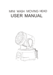
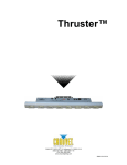
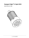
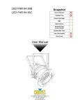
Product Overview
DMX In
DMX Out
Power Input
LCD
Controller
Output
On/Off
Switch
Programming
Buttons
4
ILUMICON User Manual (Rev. 02)
Product Description
Product Dimensions
ILUMICON User Manual (Rev. 02)
5
Installation
3. Installation
Always connect
the ILUMICON
and its controlled
fixtures to a protected
circuit with an appropriate
electrical ground to avoid
the risk of electrocution or
fire.
Never connect
the ILUMICON to
a rheostat
(variable resistor) or
dimmer circuit, even if the
rheostat or dimmer
channel serves only as a
0 to 100% switch.
6
AC Power
The ILUMICON Controller has an external voltage adapter that provides it with 12
VDC (500 mA minimum). The input voltage for this voltage adapter is set to match the
mains voltage where the ILUMICON will operate. Please refer to the sticker on the
voltage adapter for more information.
Make sure that you are connecting the ILUMICON to the proper voltage, as per the
specifications in this User Manual or on the product’s sticker.
Power Consumption
To determine the power requirements for the ILUMICON see the label affixed
to the side of the product. Alternatively, you may refer to the corresponding
specifications chart in the Technical Information chapter of this manual.
The listed current rating indicates the maximum current draw during normal
operation.
ILUMICON User Manual (Rev. 02)
Installation
DMX Linking
If using the ILUMICON Controller along with other DMX compatible fixtures, it is
possible to control them individually with a single DMX controller. DMX compatible
fixtures use a serial data link between them. If you are not familiar with the DMX
standard, or if you need information about the DMX cables needed to link the
ILUMICON to a DMX controller, you may download the “DMX Primer” from the
ILUMINARC® website at http://www.iluminarc.com/reports/dmx-primer
DMX Connection
The ILUMICON uses the standard DMX data connection for its 4-channel
DMX mode. Refer to the Introduction chapter for a brief description of this
mode and the Operation Instructions chapter to learn how to configure the
ILUMICON to work in this mode. The DMX Channel Values section will give
you detailed information regarding the 4-channel DMX mode.
The procedure below illustrates a possible connection method.
1. Connect the 3-pin, male connector of the first DMX cable to the DMX
Output connector (3-pin, female) of the DMX controller.
2. Connect the 3-pin, female connector of the first DMX cable coming from
the controller to the DMX Input connector (3-pin, male) of the
ILUMICON.
3. Connect the 3-pin, male connector of the second DMX cable to the DMX
Output connector (3-pin, female) of the ILUMICON
4. Connect the 3-pin, female connector of the second DMX cable coming
from the ILUMICON to the DMX Input connector of the first DMX
compatible product.
5. Continue linking the other DMX compatible products in the same way.
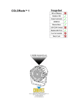
DMXConnectionDiagram
Universal DMX Controller
DMX Output
First DMX
Cable
Second DMX
Cable
ILUMICON
ILUMICON
Output Cable
ILUMICON User Manual (Rev. 02)
Third DMX
Cable
First DMX Fixture
Compatible
ILUMINARC®
Products
Next DMX
Product
7
Installation
Installation Notes
The ILUMICON consists of two parts, the controller housing and the external power adapter. The
controller housing is IP20-rated.
Always keep the
power cables away
from the signal
cables by running
them in different conduits
and using separate
distribution boxes.
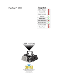
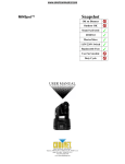
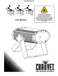
Setup
Product Control Panel Setup:
Activate ID addressing in each product by setting panel function {ID ON/OFF} to ON.
{MENU} {Settings) {ID ON/OFF} [ON]
Set ID addresses in each product by setting panel function {ID address} to incremental
values. (i.e. 1,2,3,4,5,6,etc…)
{MENU} {Settings} {ID address} [01 ~ 66]
It is not necessary to set the DMX address.
Controller Setup:
When using the {Effect program} function, it is necessary to set the {Settings} {Range}
setting, which is the quantity of products in series.
{MENU} {Settings} {Range} [ (No. of fixtures) ]
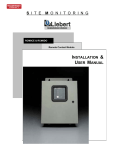
Single Row
Application
SET
UP
DOWN
ID Address: 01
EXIT
ID Address: 02
ID Address: 04
ID Address: 05
ID Address: 06
The product above shows 6 products connected in series with
corresponding addresses. Each product has {ID ON} in the product’s
settings. You must set the {Range} settings in the controller to [006]
before accessing {Effect} programs.
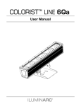
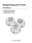
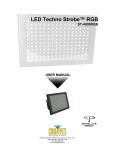
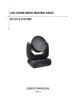
Repeat Row Block Application
Block Application
ID Address:
ID Address:
ID Address:
ID Address:
ID Address:
ID Address:
ID Address:
ID Address:
ID Address:
ID Address:
ID Address:
ID Address:
ID Address:
ID Address:
ID Address:
ID Address:
The figure above shows 9 products
connected in series. Three rows
comprised of 3 products are addressed
identically. Each product has {ID ON} in
the product’s settings. You must set the
{Range} settings in the controller to [003]
before accessing {Effect} programs.
8
ID Address: 03
SET
UP
DOWN
EXIT
ID Address:
The figure above shows 9 fixtures
connected in series with
corresponding addresses. Each
fixture has {ID ON} in the fixture’s
settings. You must set the
{Range} settings in the controller
to [009] before accessing {Effect}
programs.
ID Address:
SET
UP
DOWN
EXIT
ILUMICON User Manual (Rev. 02)
Installation
Product Linking
Products on a
serial data link
must be daisy
chained in one single line.
To comply with the EIA485 standard no more than
32 devices should be
connected on one data
link. Connecting more than
32 products on one serial
data link without the use of
a DMX optically-isolated
splitter may result in
deterioration of the digital
DMX signal.
Use a serial data link for one or more products using a DMX-512 controller or products set to
Master/Slave operating mode. The combined number of channels required by all the fixtures on
a serial data link determines the number of fixtures the data link can support.
Maximum recommended serial data link distance: 500 meters (1,640 ft.)
Maximum recommended number of fixtures on a serial data link: 32 fixtures.
Data Cabling
DMX Data Cable
Use a Belden© 9841 or equivalent cable which meets the specifications for EIA RS-485
applications. Standard microphone cables cannot transmit DMX data reliably over long
distances. The cable must have the following characteristics:
2-conductor twisted pair plus a shield
Maximum capacitance between conductors – 30 pF/ft
Maximum capacitance between conductor and shield – 55 pF/ft
Maximum resistance of 20 ohms/1,000 ft
Nominal impedance 100~140 ohms
Cable Connectors
Cabling must have male and female XLR connectors.
Make sure to
mount this product
away from any
flammable material as
indicated in the Safety
Notes.
Do not allow
contact between
the common and
the product’s chassis
ground. Grounding the
common can cause a
ground loop, and your
fixture may perform
erratically. Test cables with
an ohm meter to verify
correct polarity and to
make sure the pins are not
grounded or shorted to the
shield or each other.
Cable Connectors
If you use a controller with a 5-pin DMX Output connector, you will need to use a 5-pin to 3-pin
adapter. Iluminarc® Model No. DMX5M or DMX5F.
3 PIN TO 5 PIN CONVERSION CHART
Conductor
3 Pin Female (output)
5 Pin Male (Input)
Ground/Shield
Pin 1
Pin 1
Data ( - ) signal
Pin 2
Pin 2
Data ( + ) signal
Pin 3
Pin 3
For further information on cabling for DMX, including how to set up a DMX serial data link,
download the “DMX Primer” from the ILUMINARC® website at www.iluminarc.com.
ILUMICON User Manual (Rev. 02)
9
Installation
Mounting
Make sure there
is a suitable
power outlet for
the ILUMICON’s
voltage adapter near the
location where you will
mount the ILUMICON unit.
Before mounting this product, read and follow the safety recommendations indicated in the
Safety Notes. Always mount this product in a safe position, making sure there is adequate room
for ventilation, configuration, and maintenance.
Installation
The ILUMICON consists of a main unit and an external power adapter. ILUMINARC®
recommends following the general guidelines below when mounting the ILUMICON.
Consider ease of access to the product for operation, programming adjustments and
routine maintenance.
Never mount the product in places where rain, high humidity, extreme temperature
changes, or restricted ventilation may affect it.
Procedure
You should mount the ILUMICON’s baseplate on a flat, dry surface, whether plywood
or other suitable material. The ILUMICON’s detachable baseplate has four holes to
accommodate regular screws for this purpose.
In any case, remember the recommendations indicated above regarding access to the
product and necessary room for ventilation.
The diagram below shows the detachable baseplate and its three nipples. These must
slide all the way inside the corresponding slots on the back of the ILUMICON to
ensure a safe unit rigging.
ILUMICON
Output
Baseplate
Nipples
ILUMICON
10
Mounting
screws
ILUMICON User Manual (Rev. 02)
Operation
4. Operation
Control Panel Description
Button
Function
Accesses main menu or exits from the current
menu or function
Enables the currently displayed menu or sets the
<SETUP>
currently selected value in to the current function
Navigates upwards through the menu list and
<UP>
increases the numeric value when in a function
Navigates downwards through the menu list and
<DOWN>
decreases the numeric value when in a function
<MODE>
MODE
SETUP
UP
DOWN
Setup
When
programming live
performances as
well as cues that need to
trigger on demand or on a
timeline, program no more
than 10 products on ID
addressing per DMX
channel. This is to remain
within a one-second
execution time.
ILUMICON User Manual (Rev. 02)
1.
Connect from the OUT on the controller to the DMX Input side of the ILUMICON
using a DMX XLR cable.
2.
It is recommended that you power up all products connected prior to turning on the
controller. This ensures that the controller will auto-detect all DMX addresses.
Alternatively you can use {Detect device} from the {Settings} menu.
3.
Set ID addresses on the units in ascending order.
4.
Set the {Range} in the {Settings} menu.
5.
Note: There is no need to set ID and Range for {Wash} programs.
11
Operation
Menu Map
Main Function Selection
Selection
Selection
Defines the duration of each
program step
Defines the fade time for each
program step
Wash program
Wash [1]
Wash [8]
Edit
Step time
[001] [255]
Fade time
[001] [255]
Effect program
Effect [1]
Effect [8]
Edit
Speed
Defines the speed of the effect
[001] [100] program
Custom program
Play schedule
Custom [1]
Custom [8]
Clock
Edit time
Schedule
Settings
Password
ID address [000*] [066]
(*0 = all units)
Step time [000] [255]
Fade time [000] [255]
Scene [1]
Red [000] [255]
Scene [100]
Green [000] [255]
Blue [000] [255]
Module [001] [006]
Strobe [000] [020]
Activates the pre-configured
schedule(s)
Edit
Schedule
Time now
12
Selection
Wash [1]
Wash [8]
Effect [1]
Effect [8]
Custom [1]
Custom [8]
DMX
address
Range
Allow edit
Detect
device
Reset to
Factory
settings
Password
ON/OFF
Set
password
i.e.
12/31/2006
13:50:24
i.e.
12/31/2006
13:50:24
Shows current time and date
Edits time and date
Start>>>End
00:00>>00:00
Sets the daily schedule for
each Wash, Effect and Custom
program
[001] [250]
Sets the unit’s DMX address
[001] [100]
[YES] [NO]
Limits the ID address range
Allows or denies editing
>>>
Detects a specific device
[YES] [NO]
Defaults the COLOR-CON to
its factory settings
[ON] [OFF]
Sets the unit’s password
[
]
ILUMICON User Manual (Rev. 02)
Operation
Wash Program
Select from the eight existing [Wash] programs and it will instantly play.
Set the [Step time] and the [Fade time] in the [Edit] function if desired.
The unit of time is 5 seconds and it can be adjusted 001~255.
Effect Program
Select from the eight existing [Effect] programs and it will instantly play.
Vary the [Speed] of the effect 001~255.
Custom Program
Select from the eight existing [Custom] programs and it will instantly play.
Enter the [Edit] section to create or edit program.
You can create or edit up to 100 scenes. To program less than 100 scenes, set the [Step time] of the
scene after your last scene to 0.
Select the ID address of the target product. Setting ID address to 0 selects all products in the serial
link. Color/Effects combination for different IDs is allowed.
Specify the [Module] or modules to run active.
0 = 1,2,3
1=1
2=2
3=3
4 = 1,2
5 = 2,3
6 = 1,3
RGB mix using the [Red], [Green] and [Blue] functions and adjusting the range between 0 and
255.
Select a [Strobe] speed from 0-20 Hz if desired.
Select the [Step time] for the current scene.
Step time unit values
Range 0~10
=
0.1sec per unit
Range 11~255 =
1 sec per unit
Set a [Fade time] for the current scene in one second increments from 0 to 255.
Play Schedule
Simply activate this menu [Play schedule] to run.
Clock
[Clock] [Time now]: To view the current time on the controller.
[Clock] [Edit now]: Edit the time and date.
Schedule
There are 24 Wash, Effect, and Custom programs that can be set with Start and End times. Start
times take priority over End times; programs will not overlap. Programs with the most recent Start
time will always override the existing previously executed program.
ILUMICON User Manual (Rev. 02)
13
Operation
Settings
[DMX address]
This function sets the DMX address for the controller. It is addressable 001~250.
[Range]
Enter the number of products connected in series.
[Allow edit]
This function either enables or disables editing in Wash, Effect and Custom programs.
[Detect device]
This is the manual method of detecting and connecting the controller to all new products in series. It
is generally used when you add more products to an existing system. Turning off and then on the
controller has the same effect.
[Reset to factory settings]
This function will reset all the settings to the factory defaults except for [Custom] programs.
Factory Default Settings
Setting
Default
[Schedule]
[Wash program]
[Effect program]
[DMX address]
[Range]
[Allow edit]
[Password
ON/OFF]
All times in schedule are reset to [00:00]
Step times and fade times are reset to [001]
Speeds are reset to [001]
DMX address is reset to [001]
Range is reset to [066]
Reset to [Yes]
[Set password]
Password is reset to [OFF]
Password is reset to [00000000]
Down=0, Up=1
Activating Password Mode
Set [Password] function to [ON]. This will prompt the user for a password every time the controller
is powered on.
Toggle to [Set password] function in order to change the password.
Input an eight-digit password using the [UP] & [DOWN] keys. Press the [SET] button to confirm.
Control via External DMX
Programs in the controller can be accessed via an external DMX controller. It will be necessary to
have the DMX address set on the ILUMICON controller. The controller operates on four channels
of DMX control.
14
ILUMICON User Manual (Rev. 02)
Operation
DMX Channel Values
Channel
1
2
3
4
Value
Function
000 010
011 030
031 040
041 060
061 070
071 090
091 100
101 120
121 130
131 150
151 160
161 180
181 190
191 210
211 220
221 255
000 010
011 030
031 040
041 060
061 070
071 090
091 100
101 120
121 130
131 150
151 160
161 180
181 190
191 210
211 220
221 255
000 010
011 030
031 040
041 060
061 070
071 090
091 100
101 120
121 130
131 150
151 160
161 180
181 190
191 210
211 220
221 255
000 127
128 255
Blackout
Wash [1]
Blackout
Wash [2]
Blackout
Wash [3]
Blackout
Wash [4]
Blackout
Wash [5]
Blackout
Wash [6]
Blackout
Wash [7]
Blackout
Wash [8]
Blackout
Effect [1]
Blackout
Effect [2]
Blackout
Effect [3]
Blackout
Effect [4]
Blackout
Effect [5]
Blackout
Effect [6]
Blackout
Effect [7]
Blackout
Effect [8]
Blackout
Custom [1]
Blackout
Custom [2]
Blackout
Custom [3]
Blackout
Custom [4]
Blackout
Custom [5]
Blackout
Custom [6]
Blackout
Custom [7]
Blackout
Custom [8]
OFF
ON
ILUMICON User Manual (Rev. 02)
15
Technical Information
5. Technical Information
Product Maintenance
To maintain optimum performance and minimize wear, clean the product frequently. Usage and
environment are contributing factors in determining the cleaning frequency. As a general
guideline, the product should be cleaned at least twice a month. Dust build-up reduces
performance and can cause overheating.
To clean a product:
Always dry the
external surfaces
carefully after
cleaning them.
Unplug the product from power.
Wait until the product has cooled.
Use a vacuum (or dry compressed air) and a soft brush to remove dust collected on the
external vents and reachable internal components.
Clean all plastic surfaces with mild soapy water and a soft, lint-free cotton cloth or a
lens-cleaning tissue.
Product Repairs
ILUMINARC® strongly advises you against attempting any repairs to this product unless you
are an authorized ILUMINARC® technician.
ILUMINARC® presents the information contained in the Troubleshooting Guide as potential
solutions only. In most cases, opening the product’s housing will invalidate its warranty, unless
there is a written indication to the contrary.
Troubleshooting Guide
Symptom
If you still experience
technical
problems after
trying the
solutions in the
Troubleshooting Guide,
contact ILUMINARC®
Technical Support.
16
Loss of signal
Chase is too slow
Device has no power
Action(s)
Use only DMX-compatible cables
Install terminator as suggested in the “DMX
Primer” on the Iluminarc® website
Check speed adjustment
Check for power on mains
Check I/O ports on adapter
ILUMICON User Manual (Rev. 02)
Technical Information
Returns Procedure
ILUMINARC®
reserves the
right to use its
own discretion to repair or
replace returned
product(s).
You must send the merchandise prepaid, in the original box, and with its original packing and
accessories. ILUMINARC® will not issue call tags.
Call ILUMINARC® and request a Return Merchandise Authorization Number (RMA #) before
shipping the product. Be prepared to provide the model number, serial number, and a brief
description of the cause for the return.
The user must clearly label the package with an RMA #. ILUMINARC® will refuse any
product returned without an RMA #. DO NOT write the RMA # directly on the box. Instead,
write it on a properly affixed label.
Once you receive the RMA #, please include the following information on a piece of paper
inside the box:
Your name
Always keep the
original box and
all packaging
material as you
will need those to ship the
product back to
ILUMINARC®.
Your address
Your phone number
The RMA #
A brief description of the problem
Be sure to pack the product properly. Any shipping damage resulting from inadequate
packaging will be the customer’s responsibility. As a suggestion, proper FedEx packing or
double-boxing are the shipping methods ILUMINARC® recommends.
Contact Us
World Wide
General Information
ILUMINARC®
5200 NW 108th Avenue
Sunrise, FL 33351
Voice: (954) 923-3680
Fax: (954) 929-5571
Email: [email protected]
Customer Support
World Wide Web
ILUMICON User Manual (Rev. 02)
Voice: (954) 923-3680 (ext. 4000)
Fax: (954) 756-8015
Email: [email protected]
www.iluminarc.com
17
ILUMICON User Manual
Technical Specifications
Dimensions and
Weight
Length
Width
Height
Weight
7 in (178 mm)
5.2 in (131 mm)
2 in (51 mm)
1 lb (0.5 kg)
Note: Dimensions in inches rounded to the nearest decimal digit.
Electrical
Power Supply Type
Range
External power adapter
120~230 V, 50/60 Hz
Parameter
Consumption
Thermal
13 W Max
Max. External Temperature
104° F (40° C)
Control &
Programming
Ordering
I/O Connectors
Connector Type
Channel Range
3-pin XLR
Sockets
1, 2, 3, 4
ILUMICON
5555502
Technical Information
ILUMINARC®
5200 NW 108th Avenue
Sunrise, FL 33351 U.S.A.
Voice: (954) 923-3680
www.iluminarc.com
ILUMICON User Manual Rev. 02
January 2012
ILUMICON User Manual (Rev. 02)
19