1
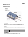
Chapter 3 Functional Details External components The USB-3110 has the following external components, as shown in Figure 3. USB connector USB LED Power connector Power LED Screw terminal banks (2) Figure 3. USB-3110 external components USB connector The USB connector provides communication. Use the external power supply that shipped with the USB-3110 to power the device. USB LED The USB LED indicates the communication status of the USB-3110. It uses up to 10 mA of current and cannot be disabled. The table below defines the function of the USB LED. LED Illumination LED Illumination Indication Steady green Blinks continuously The USB-3110 is connected to a computer or external USB hub. Data is being transferred. Power connector Connect the external power adapter (MCC part number PS-5V2AEPS) to this connector. 12