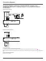
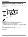
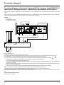
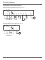
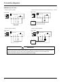
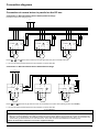
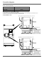
1
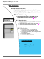
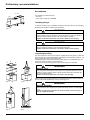
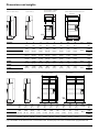
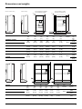
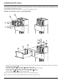
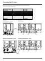
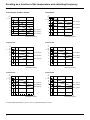
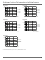
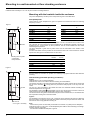
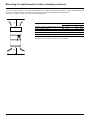
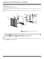
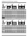
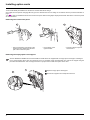
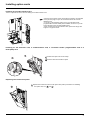
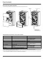
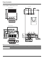
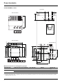
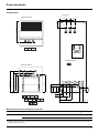
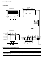
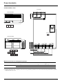
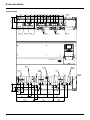
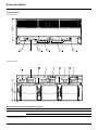
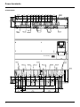
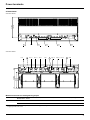
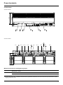
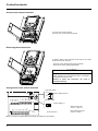
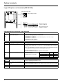
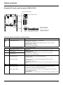
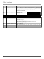
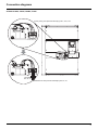
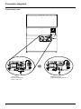
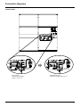
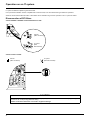
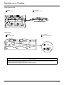
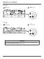
Altivar 61
Installation Manual
Variable speed drives
for asynchronous motors
Retain for future use
55 kW (75 HP) ... 90 kW (125 HP) / 200 -240V
90 kW (125 HP) ... 630 kW (900 HP) / 380 - 480V
Contents
Contents ____________________________________________________________________________________________________ 3
Before you begin______________________________________________________________________________________________ 4
Steps for setting up the drive ____________________________________________________________________________________ 5
Preliminary recommendations ___________________________________________________________________________________ 6
Drive ratings _________________________________________________________________________________________________ 8
Dimensions and weights_______________________________________________________________________________________ 10
Installing the DC choke________________________________________________________________________________________ 12
Connecting the DC choke______________________________________________________________________________________ 13
Derating as a function of the temperature and switching frequency______________________________________________________ 14
Mounting in a wall-mounted or floor-standing enclosure ______________________________________________________________ 16
Installing the kit for IP31/UL Type 1 conformity _____________________________________________________________________ 19
Position of the charging LED ___________________________________________________________________________________ 21
Installing option cards _________________________________________________________________________________________ 22
Wiring recommendations ______________________________________________________________________________________ 24
Power terminals _____________________________________________________________________________________________ 26
Control terminals_____________________________________________________________________________________________ 38
Option terminals _____________________________________________________________________________________________ 40
Connection diagrams _________________________________________________________________________________________ 45
Operation on an IT system _____________________________________________________________________________________ 58
Electromagnetic compatibility, wiring _____________________________________________________________________________ 61
3
Before you begin
Read and understand these instructions before performing any procedure on this
drive.
DANGER
HAZARDOUS VOLTAGE
• Read and understand this manual before installing or operating the Altivar 61 drive.
Installation, adjustment, repair and maintenance must be performed by qualified
personnel.
• The user is responsible for compliance with all international and national electrical
standards in force concerning protective grounding of all equipment.
• Many parts of this variable speed drive, including the printed circuit boards, operate
at the line voltage. DO NOT TOUCH.
Use only electrically insulated tools.
• DO NOT touch unshielded components or terminal strip screw connections with
voltage present.
• DO NOT short across terminals PA and PC or across the DC bus capacitors.
• Install and close all the covers before applying power or starting and stopping the
drive.
• Before servicing the variable speed drive
- Disconnect all power.
- Place a “DO NOT TURN ON” label on the variable speed drive disconnect.
- Lock the disconnect in the open position.
• Disconnect all power including external control power that may be present before
servicing the drive. Wait for the charging LED to go off. Then follow the DC bus voltage
measurement procedure on page 21 to verify that the DC voltage is less than 45 V.
The drive LEDs are not accurate indicators of the absence of DC bus voltage.
Electric shock will result in death or serious injury.
CAUTION
IMPROPER DRIVE OPERATION
• If the drive is not turned on for a long period, the performance of its electrolytic
capacitors will be reduced.
• If it is stopped for a prolonged period, turn the drive on every two years for at least
5 hours to restore the performance of the capacitors, then check its operation. It is
recommended that the drive is not connected directly to the line voltage. The voltage
should be increased gradually using an adjustable AC source.
Failure to follow this instruction can result in equipment damage.
4
Steps for setting up the drive
INSTALLATION
b 1 Take delivery of the drive
v Check that the catalog number printed on the label is the same
as that on the purchase order
v Remove the Altivar from its packaging and check that it has not
been damaged in transit
b 2 Check the line voltage
v Check that the line voltage is compatible with the
voltage range of the drive (see pages 8 and 9)
Steps 1 to 4 must
be performed with
the power off
b 3 Mount the drive
v Mount the drive in accordance with the instructions
in this document
v Install and connect the DC choke (see page 12)
v Install any internal and external options
b 4 Wire the drive
v Connect the motor, ensuring that its
connections correspond to the voltage
v Connect the line supply, after making sure that
it is turned off
v Connect the control
v Connect the speed reference
PROGRAMMING
v 1 Please refer to the
programming manual
5
Preliminary recommendations
Acceptance
DC choke
The packaging contains two items:
- The drive
- A DC choke, except for ATV61pppD
ATV61
Handling/storage
To protect the drive prior to installation, handle and store the device in its packaging.
Ensure that the ambient conditions are acceptable.
Figure 1
WARNING
DAMAGED PACKAGING
If the packaging appears damaged, it can be dangerous to open it or handle it.
Take precautions against all risks when performing this operation.
Failure to follow this instruction can result in death or serious injury.
WARNING
DAMAGED EQUIPMENT
Do not operate or install any drive that appears damaged.
Failure to follow this instruction can result in death or serious injury.
Unpacking/handling
The drive and the DC choke are mounted on a pallet with screws (figure 1). When the
DC choke is present, it is supplied already assembled to make it easier to transport. The
unit should be unpacked in the following order:
1 Dissassemble the components of the DC choke (figure 2) for installation later, and
remove the choke by means of a hoist (figure 3).
2 Remove the fixing screws (figure 3) from the choke support on the pallet.
WARNING
RISK OF CUTS
The fixing screws that hold the choke support on the pallet are difficult to access,
leading to a risk of cutting oneself. Take all possible measures to avoid this risk,
and use protective gloves.
Failure to follow this instruction can result in serious injury.
3 Remove the screws holding the drive on the pallet and lift off the drive by means of a
hoist. It is fitted with handling lugs for this purpose (figure 4).
Figure 3
Figure 2
WARNING
RISK OF TOPPLING
Never stand the drive upright (figure 5) without keeping hold of it, or it will topple
over.
Failure to follow this instruction can result in death or serious injury, as
well as equipment damage.
60°
max.
Figure 4
6
Figure 5
Preliminary recommendations
Installing the drive
- Mount the drive on a wall or the back of the enclosure in accordance with the recommendations described in this document, before
installing the DC choke.
Installing the DC choke
ATV61H D55M3XD to D90M3XD and ATV61H D90N4D to C63N4D drives are supplied without a DC choke.
ATV61H D55M3X to D90M3X and ATV61H D90N4 to C63N4 drives are supplied with a DC choke that must be installed on top of the drive
and wired in accordance with the recommendations described in this document. This choke must be used for connecting drives to the
3-phase line supply.
- Mount the DC choke on the back of the enclosure or on the wall above the drive and connect it up. The instructions for installing and
connecting the choke are given on page 12.
- Make sure that the seal between the drive and the choke chassis is doing its job properly.
Precautions
Read and understand the instructions in the Programming Manual.
CAUTION
INCOMPATIBLE LINE VOLTAGE
Before turning on and configuring the drive, ensure that the line voltage is compatible with the supply voltage range shown
on the drive nameplate. The drive may be damaged if the line voltage is not compatible.
Failure to follow this instruction can result in equipment damage.
DANGER
UNINTENDED EQUIPMENT OPERATION
• Before turning on and configuring the Altivar 61, check that the PWR (POWER REMOVAL) input is deactivated (at
state 0) in order to prevent unintended operation. Do not forget to reactivate the Power Removal input to start the motor.
• Before turning on or on exiting the configuration menus, check that the inputs assigned to the run command are
deactivated (at state 0) since they can cause the motor to start immediately.
Failure to follow these instructions will result in death or serious injury.
If the safety of personnel requires the prohibition of unwanted or unintended starts, electronic locking is performed by the Altivar 61's
Power Removal function.
This function requires the use of connection diagrams conforming to category 3 of standard EN954-1 and safety integrity level 2
according to IEC/EN61508.
The Power Removal function takes priority over any run command.
7
Drive ratings
Powers in kW
3-phase supply voltage: 200…240 V 50/60 Hz
3-phase motor 200...240 V
Motor
Power
indicated on
plate (1)
kW
55
75
90
Line supply (input)
Line current (2)
at 200 V
A
200
271
336
at 240 V
A
173
232
288
Max.
Apparent
prospective power
line Isc (4)
Drive (output)
Max. available Max. transient
nominal
current (1) for
current In (1)
60 s
kA
35
35
35
A
221
285
359
kVA
72
96
120
A
265
313
395
Altivar 61
Catalog number (3)
ATV61HD55M3X
ATV61HD75M3X
ATV61HD90M3X
3-phase supply voltage: 380…480 V 50/60 Hz
3-phase motor 380...480 V
Motor
Power
indicated on
plate (1)
kW
90
110
132
160
200
220
250
280
315
355
400
500
560
630
Line supply (input)
Line current (2)
at 380 V
A
166
202
239
289
357
396
444
494
555
637
709
876
978
1091
at 480 V
A
143
168
224
275
331
383
435
494
544
597
644
760
858
964
Max.
Apparent
prospective power
line Isc (4)
kA
35
35
35
50
50
50
50
50
50
50
50
50
50
50
kVA
109
133
157
190
235
261
292
365
365
419
467
577
644
718
Drive (output)
Max. available Max. transient
nominal
current (1) for
current In (1)
60 s
Altivar 61
Catalog number (3)
A
179
215
259
314
427
A
215
236
285
345
470
ATV61HD90N4
ATV61HC11N4
ATV61HC13N4
ATV61HC16N4
ATV61HC22N4
481
616
529
678
ATV61HC25N4
ATV61HC31N4
759
835
ATV61HC40N4
941
1188
1035
1307
ATV61HC50N4
ATV61HC63N4
(1) These power ratings and currents are given for an ambient temperature of 45°C (122°F) and at the factory-set switching frequency of
2.5 kHz, used in continuous operation.
Above 2.5 kHz, the drive will reduce the switching frequency automatically in the event of excessive temperature rise. For continuous
operation above 2.5 kHz, derating must be applied to the drive nominal current in accordance with the curves on pages 14 and 15.
(2) Typical value for the indicated motor power, with a standard 4-pole motor on a line supply with the indicated "prospective line Isc".
(3) The drives are supplied as standard with a DC choke which must be used for connecting the drive on a 3-phase line supply.
For connections on the DC bus, the drive can be controlled without a choke. Add the letter D at the end of the reference.
Example: ATV 61HD90N4 becomes ATV 61HD90N4D.
(4) If the drive is installed on a line supply with a prospective short circuit current that is higher than the value given in this column, use line
chokes (please refer to the catalog).
8
Drive ratings
Powers in HP
3-phase supply voltage: 200…240 V 50/60 Hz
3-phase motor 200...240 V
Motor
Power
indicated on
plate (1)
HP
75
100
125
Line supply (input)
Line current (2)
at 200 V
A
200
271
336
at 240 V
A
173
232
288
Max.
Apparent
prospective power
line Isc (4)
Drive (output)
Max. available Max. transient
nominal
current (1) for
current In (1)
60 s
kA
35
35
35
A
221
285
359
kVA
72
96
120
A
265
313
395
Altivar 61
Catalog number (3)
ATV61HD55M3X
ATV61HD75M3X
ATV61HD90M3X
3-phase supply voltage: 460...480 V 50/60 Hz
3-phase motor 480 V
Motor
Power
indicated on
plate (1)
HP
125
150
200
250
300
350
400
450
500
600
700
800
900
Line supply (input)
Line current (2)
Max. prospective Apparent power
line Isc (4)
at 480 V
A
143
168
224
275
331
383
435
494
544
597
644
760
858
964
kA
35
35
35
50
50
50
50
50
50
50
50
50
50
50
kVA
109
133
157
190
235
261
292
365
365
419
467
577
644
718
Drive (output)
Max. available Max. transient
nominal
current (1) for
current In (1)
60 s
Altivar 61
Catalog number (3)
A
179
215
259
314
427
A
215
236
285
345
470
ATV61HD90N4
ATV61HC11N4
ATV61HC13N4
ATV61HC16N4
ATV61HC22N4
481
616
529
678
ATV61HC25N4
ATV61HC31N4
759
835
ATV61HC40N4
941
1188
1035
1307
ATV61HC50N4
ATV61HC63N4
(1) These power ratings and currents are given for an ambient temperature of 45°C (122°F) and at the factory-set switching frequency of
2.5 kHz, used in continuous operation.
Above 2.5 kHz, the drive will reduce the switching frequency automatically in the event of excessive temperature rise. For continuous
operation above 2.5 kHz, derating must be applied to the drive nominal current in accordance with the curves on pages 14 and 15.
(2) Typical value for the indicated motor power, with a standard 4-pole motor on a line supply with the indicated "prospective line Isc".
(3) The drives are supplied as standard with a DC choke which must be used for connecting the drive on a 3-phase line supply.
For connections on the DC bus, the drive can be controlled without a choke. Add the letter D at the end of the reference.
Example: ATV 61HD90N4 becomes ATV 61HD90N4D.
(4) If the drive is installed on a line supply with a prospective short circuit current that is higher than the value given in this column, use line
chokes (please refer to the catalog).
9
Dimensions and weights
With 0 or 1 option card (1)
ATV61H D55M3X to D90M3X
ATV61H D90N4 to C31N4
2 option cards (1)
670 (26.37)
H
b
K1 K
K2
a
ATV61H C25N4 to C31N4 with braking unit
392 mm
(15.43 in)
377 mm
(14.77 in)
ATV61H
=
G
540 mm (21,26 in)
=
102,5 mm 27,5 mm
(4.03 in) (1.08 in)
a
mm
(in.)
b
mm
(in.)
G
mm
(in.)
H
mm
(in.)
K
mm
(in.)
K1
mm
(in.)
K2
mm
(in.)
Ø
mm
(in.)
320
(12.60)
920
(36.22)
250
(9.84)
650
(25.59)
150
(5.91)
75
(2.95)
30
(1.18)
11.5
(0.45)
360
(14.17)
340
(13.39)
440
(17.32)
1022
(40.23)
1190
(46.62)
1190
(46.62)
298
(11.73)
285
(11.22)
350
(13.78)
758
(29.84)
920
(36.22)
920
(36.22)
150
(5.91)
150
(5.91)
150
(5.91)
72
(2.83)
75
(2.95)
75
(2.95)
30
(1.18)
30
(1.18)
30
(1.18)
11.5
(0.45)
11.5
(0.45)
11.5
(0.45)
595
(23.43)
1190
(46.62)
540
(21.26)
920
(36.22)
150
(5.91)
75
(2.95)
30
(1.18)
11.5
(0.45)
For
screws
weight
kg
(lb.)
60
(132)
74
(163)
80
(176)
110
(242)
140
(309)
140
(309)
215
(474)
D55M3X, D90N4
D75M3X, C11N4
C13N4, D90M3X
C16N4
C22N4
M10
M10
M10
M10
C25N4
C31N4
With 0 or 1 option card (1)
2 option cards (1)
ATV61H C40N4 to C50N4
ATV61H C63N4
a
a
J1
J1
K2
J
J
J1
H
b
K1 K
J1
M10
377 mm
(14.77 in)
ATV61H
=
392 mm
(15.43 in)
G
G
=
=
G
G
a
mm
(in.)
b
mm
(in.)
G
mm
(in.)
J
mm
(in.)
J1
mm
(in.)
H
mm
(in.)
K
mm
(in.)
K1
mm
(in.)
K2
mm
(in.)
Ø
mm
(in.)
890
(35.04)
1390
(54.72)
417.5
(16.44)
70
(2.76)
380
(14.96)
1120
(44.09)
150
(5.91)
75
(2.95)
30
(1.18)
11.5
(0.45)
1120
(44.09)
1390
(54.72)
532.5
(20.96)
70
(2.76)
495
(1949)
1120
(44.09)
150
(5.91)
75
(2.95)
30
(1.18)
11.5
(0.45)
=
For
screws
C40N4
C50N4
C63N4
M10
M10
weight
kg
(lb.)
225
(496)
300
(661)
300
(661)
(1) For the addition of I/O extension cards, communication cards, the multi-pump card or the "Controller Inside" programmable card.
10
Dimensions and weights
ATV61H D55M3XD to D90M3XD
ATV61H D90N4D to C28N4D
H
b
ATV61H
G
a
=
392 mm
(15.43 in)
377 mm
(14.84 in)
4x
h
4x
ATV61H C25N4D to C31N4D
with braking unit (VW3A7 101)
h
2 option cards (1)
H
With 0 or 1 option card (1)
=
97,5 mm
(3.82 in.)
22,5 mm
(0.88 in.)
540 mm (21.17 in.)
660 mm (25.87 in.)
a
mm
(in.)
b
mm
(in.)
G
mm
(in.)
H
mm
(in.)
H
mm
(in.)
Ø
mm
(in.)
310
(12.20)
680
(26.77)
250
(9.84)
650
(25.59)
15
(0.59)
11.5
(0.45)
350
(13.78)
330
(12.99)
430
(16.33)
782
(30.79)
950
(37.4)
950
(37.4)
298
(11.73)
285
(11.22)
350
(13.78)
758
(29.84)
920
(36.22)
920
(36.22)
12
(0.47)
15
(0.59)
15
(0.59)
11.5
(0.45)
11.5
(0.45)
11.5
(0.45)
585
(23.03)
950
(37.4)
540
(21.26)
920
(36.22)
15
(0.59)
11.5
(0.45)
For
screws
D55M3XD, D90N4D
D75M3XD, C11N4D
C13N4D, D90M3XD
C16N4D
C22N4D
M10
M10
M10
M10
C25N4D
C31N4D
2 option cards (1)
ATV61H C40N4D to C50N4D
ATV61H C63N4D
377 mm
(14.84 in)
ATV61H
H
b
K
With 0 or 1 option card (1)
M10
weight
kg
(lb.)
60
(132)
74
(163)
80
(176)
110
(242)
140
(309)
140
(309)
215
(474)
=
392 mm
(15.43 in)
G
G
=
=
G
G
a
mm
(in.)
b
mm
(in.)
G
mm
(in.)
H
mm
(in.)
F
mm
(in.)
Ø
mm
(in.)
880
(35.65)
1150
(54.72)
417.5
(16.44)
1120
(44.09)
415
(16.34)
11.5
(0.45)
1110
(43.49)
1150
(54.72)
532.5
(20.96)
1120
(44.09)
532.5
(20)
11.5
(0.45)
For
screws
C40N4D
C50N4D
C63N4D
=
a
a
M10
M10
weight
kg (lb.)
225
(496)
300
(661)
300
(661)
(1) For the addition of I/O extension cards, communication cards, the multi-pump card or the "Controller Inside" programmable card.
11
Installing the DC choke
This should be performed after mounting the drive and before wiring it. If a VW3 A7 101 braking module is being used, install the module
on the drive before mounting the DC choke.
During installation, ensure that no liquid, dust or conductive objects fall into the drive.
Example of installing DC chokes on an ATV61HC22N4
1
2
6
3
4
5
- Mount the DC choke chassis 1 on the wall, on top of the drive. Ensure that the chassis is tightly secured to the drive to maintain the
IP54 seal of the ventilation duct.
- Then install the DC choke 2 on the chassis 1 using the nuts provided.
- Connect the choke between the PO and PA/+ terminals on the drive (see note and next page).
- Connect the grounding strip between the DC choke chassis 1 and the drive.
- Then mount the cover 3 on the chassis and secure it with the nuts 4 provided.
- Then mount panels 5 and 6 using the screws provided.
Once the choke has been installed, the degree of protection of the top the drive is IP31.
Note: The number of DC chokes supplied with the drive varies according to the drive rating.
12
Connecting the DC choke
Between 1 and 4 chokes can be connected in parallel as described in the following examples.
Table of drive/choke combinations
Drive
ATV61HD55M3X, D75M3X
ATV61HD90M3X
ATV61HD90N4, C11N4
ATV61HC13N4
ATV61HC16N4
ATV61HC22N4
ATV61HC25N4
ATV61HC31N4
ATV61HC40N4
ATV61HC50N4
ATV61HC63N4
Number of chokes in parallel
1
1
1
1
1
2
2
2
3
4
4
Example 1:
ATV61HD55M3X ... D90M3X,
ATV61HD90N4 ... C16N4
Choke model
DC-CHOKE 5
DC-CHOKE 6
DC-CHOKE 1
DC-CHOKE 2
DC-CHOKE 4
DC-CHOKE 1
DC-CHOKE 3
DC-CHOKE 4
DC-CHOKE 3
DC-CHOKE 2
DC-CHOKE 7
Example 3:
ATV61HC40N4
Grounding
strip
PO.1
PO
Example 4: ATV61HC50N4 ... C63N4
PO.1
PA/+
PO.2
PA/+
Example 2: ATV61HC22N4 ... C31N4
PO
PA/+
PA/+
PO.2
Grounding
strip
13
Derating as a function of the temperature and switching frequency
Derating curves for the drive current In as a function of the temperature and switching frequency.
ATV61HD55M3X, HD75M3X, HD90M3X
ATV61HD90N4
%
120
110
In = 100
%
120
In = 100
90
80
70
60
80
40°C (104°F)
67
60
50°C (122°F)
40
60°C (140°F)
40°C (104°F)
50
50°C (122°F)
20
60°C (140°F)
0
40
30
2,5 kHz
4 kHz
6 kHz
2,5 kHz
8 kHz
4 kHz
ATV61HC11N4
8 kHz
ATV61HC13N4
%
120
%
120
106
In = 100
104
In = 100
91
88
80
40°C (104°F)
80
71
40°C (104°F)
61
60
50°C (122°F)
60
50°C (122°F)
40
60°C (140°F)
40
20
60°C (140°F)
20
0
0
2,5 kHz
4 kHz
6 kHz
8 kHz
2,5 kHz
4 kHz
Switching frequency
ATV61HC16N4
6 kHz
8 kHz
Switching frequency
ATV61HC22N4
%
120
%
120
104
In = 100
92
105
In = 100
90
80
80
75
40°C (104°F)
60
50°C (122°F)
60°C (140°F)
40
20
40°C (104°F)
67
60
50°C (122°F)
60°C (140°F)
40
20
0
0
2,5 kHz
4 kHz
6 kHz
8 kHz
2,5 kHz
Switching frequency
For intermediate temperatures (e.g. 55°C (131°F)), interpolate between 2 curves.
14
6 kHz
Switching frequency
Switching frequency
4 kHz
6 kHz
8 kHz
Switching frequency
Derating as a function of the temperature and switching frequency
ATV61HC25N4
ATV61HC31N4
%
120
%
120
105
In = 100
104
In = 100
92
90
80
80
69
40°C (104°F)
60
50°C (122°F)
60
40
60°C (140°F)
40
40°C (104°F)
70
50°C (122°F)
60°C (140°F)
20
20
0
0
2,5 kHz
4 kHz
6 kHz
2,5 kHz
8 kHz
4 kHz
ATV61HC40N4
6 kHz
8 kHz
Switching frequency
Switching frequency
ATV61HC50N4
%
120
%
120
105
In = 100
104
In = 100
93
90
80
40°C (104°F)
69
60
50°C (122°F)
40
60°C (140°F)
80
78
40°C (104°F)
60
50°C (122°F)
60°C (140°F)
40
20
20
0
0
2,5 kHz
4 kHz
6 kHz
2,5 kHz
8 kHz
Switching frequency
4 kHz
6 kHz
8 kHz
Switching frequency
ATV61HC63N4
%
120
104
In = 100
93
80
77
40°C (104°F)
60
50°C (122°F)
60°C (140°F)
40
20
0
2,5 kHz
4 kHz
6 kHz
8 kHz
Switching frequency
For intermediate temperatures (e.g. 55°C (131°F)), interpolate between 2 curves.
15
Mounting in a wall-mounted or floor-standing enclosure
Install the drive vertically at ± 10°. Do not place it close to heating elements.
Mounting with the heatsink inside the enclosure
The power dissipated by the drive power components is given in the table below.
Dissipated power
These levels of power dissipation are given for operation at nominal load and for a switching
frequency of 2.5 Hz.
Figure 1
ATV61H
2
D55M3X
D75M3X
D90M3X
D90N4
C11N4
C13N4
C16N4
1
ATV61
Cooling duct for power
components.
IP54 protection
Figure 2
Dissipated power
W
1715
2233
2694
2403
3056
3583
4036
ATV61H
C22N4
C25N4
C31N4
C40N4
C50N4
C63N4
Dissipated power
W
5482
6379
7867
9598
12055
15007
The drive has a fan for cooling the power components. The air is circulated from the bottom to the
top of the unit via a duct (the duct is shown shaded gray on the diagram opposite). This duct is
isolated from the control section by IP54 protection. The DC choke extends this duct while
maintaining IP54 protection.
The drive dissipates a great deal of power which must be evacuated to the outside of the
enclosure.
Air inlets and outlets must be provided to ensure that the flow of air in the enclosure is at least
equal to the value given in the table below for each drive.
ATV61H
D55M3X, D75M3X, D90N4, C11N4
D90M3X, C13N4
C16N4
C22N4
C25N4, C31N4
C40N4, C50N4
C63N4
Flow rate
m3/hour
402
774
745
860
1260
2100
2400
ft3/min
236
455
438
506
742
1236
1412
Several methods of evacuation are possible. The following is a proposed method for IP23 and IP54
mounting.
IP23 mounting (standard operating conditions):
ATV61
Figure 1
Install the drive on an enclosure baseplate.
Install the DC choke in accordance with the mounting recommendations.
The simplest mounting is to extend the IP54 duct between the upper outlet of the DC choke and
the top of the enclosure 1 . Fixing points are provided for this purpose on the top of the DC
choke.
The hot air is thus evacuated to the outside and does not contribute towards increasing the
internal temperature of the enclosure.
It is advisable to add a plate 2 approximately 150 mm from the top of the enclosure over the air
outlet opening to prevent foreign bodies falling into the drive cooling duct.
The air inlet can be via a grille on the bottom front panel of the enclosure door, in accordance with
the required flow rates given in the above table.
Figure 2
It is advisable to use a kit for IP31/UL Type 1 conformity (to be ordered as an option) for attaching
the power cables. The design of the IP31 kit is based on the same principle as the DC choke, and
has an IP54 duct to help guide the incoming air.
Kit for IP31
or UL Type 1 conformity
16
Note:
- If the air in the power circuit is totally evacuated to the outside, very little power is dissipated
inside the enclosure. In this case, use the dissipated power table for dust and damp proof flange
mounting (see the next page).
- Connect all the additional metal parts to ground.
Mounting in a wall-mounted or floor-standing enclosure
Mounting the heatsink inside the enclosure (continued)
IP54 mounting (standard operating conditions):
1
ATV61
2
4
3
5
The drive must be mounted in an IP54 enclosure in certain environmental conditions: dust,
corrosive gases, high humidity with risk of condensation and dripping water, splashing liquid,
etc.
The simplest way of obtaining an enclosure with IP54 protection is to follow the mounting
recommendations for IP23 protection with the following 5 additional points:
1 Do not make an air outlet hole for the control section. Do not make an air inlet hole in the
enclosure door. In the power section, the air will enter through the bottom of the enclosure via
a plinth added for this purpose.
2 Add the IP31 or UL Type 1 conformity kit in accordance with the mounting instructions.
3 Add an enclosure baseplate designed to provide IP54 protection around the power cables.
4 Add an air evacuation duct between the baseplate and the duct of the IP31 or UL Type 1
conformity kit. The IP31 or UL Type 1 conformity kit enables an extension duct to be mounted.
Drill a hole in the base of the enclosure to allow air to enter. Place seals around the duct that
has been added to maintain IP54 protection.
5 Add a 200 mm plinth at the bottom of the enclosure with grilles to allow air to enter.
6 Use the dissipated power table below to calculate the enclosure dimensions.
Note: Connect all the additional metal parts to ground.
Power dissipated by the control section inside the enclosure (for
calculating the enclosure dimensions)
These power ratings are given for operation at nominal load and for the factory-set switching
frequency.
ATV61H
D55M3X, D75M3X,
D90M3X
D90N4
C11N4
C13N4
C16N4
C22N4
Dissipated power (1)
W
ATV61H
Dissipated power (1)
W
154
C25N4
606
237
269
304
362
452
C31N4
C40N4
C50N4
C63N4
769
-
(1)Add 7W to this value for each option card added
Dust and damp proof flange mounting (heatsink outside
the enclosure)
This mounting is used to reduce the power dissipated in the enclosure by locating the power
section outside the enclosure.
This requires the use of the dust and damp proof flange mounting kit VW3A9509...517 (please
refer to the catalog).
The degree of protection for the drive mounted in this way becomes IP54.
To fit the kit to the drive, please refer to the manual supplied with the kit.
Check that the back of the enclosure is strong enough to support the weight of the drive.
Use the dissipated power table above to calculate the enclosure dimensions.
In this case the DC choke can be installed directly on the back of the enclosure.
17
Mounting in a wall-mounted or floor-standing enclosure
u h1
If the hot air exiting the drive is not ducted and evacuated to the outside, it risks being sucked back in, making the ventilation totally
ineffective. In order to avoid this, it is important to leave enough free space around the drive, as indicated below.
The enclosure must be cooled in order to get rid of the dissipated heat.
ATV61H
h1
mm
D55M3X, D75M3X, D90M3X, D90N4, C11N4 100
C13N4, C16N4, C22N4
150
C25N4, C31N4
200
C40N4, C50N4
300
C63N4
400
in.
3.94
5.90
7.87
11.81
15.75
u h2
Free space in front of the drive: 10 mm (0.39 in.) minimum
18
h2
mm
100
150
150
250
250
in.
3.94
5.90
5.90
9.84
9.84
Installing the kit for IP31/UL Type 1 conformity
On ATV61H D55M3X to D90M3X and D90N4 to C31N4 drives, the cable shielding can be attached and connected to ground using one of
the following two kits:
• Kit for IP31 conformity (VW3 A9 109 ... 114)
• Kit for UL Type 1 conformity (VW3 A9 209 ... 214)
On ATV61H C40N4 to C63N4 drives, the cable shielding can be attached and connected to ground using the kit for IP31 conformity
(VW3 A9 115, 116).
This kit is not supplied with the drive. It must be ordered separately (please refer to the catalog). It is mounted under the drive as shown
below.
5
2
3
4
1
EMC clamp for holding the cables in place and connecting
the shielding to ground
- Mount the chassis 1 on the wall or the back of the enclosure under the drive. Ensure that the chassis is tightly secured to the drive
to maintain the IP54 seal of the ventilation duct. To do this, use the 2 locking flanges that are attached in the drive transport holes 5 .
- Mount the EMC plate 2 on the kit chassis using the screws provided.
- Mount the bridge 3 to ensure equipotentiality of the grounds between the drive and the EMC plate.
- Then mount the IP31 or UL Type 1 cover 4 on the EMC plate using the screws provided.
Note :
This kit can be used to simplify guiding the inlet air. It is supplied with a seal to provide IP54 sealing for the duct to the drive. Close the drive
transport holes 5 with the plastic plugs provided.
19
Installing the kit for IP31/UL Type 1 conformity
VW3 A9 109 ... 113, 115
VW3 A9 114
VW3 A9 116
c
=
G
=
H2
b
H1
H3
VW3 A9 109 ... 116
G1
G
a
VW3
G2
G
=
a
G3
G
=
a
a
mm
(in.)
325
(12.80)
365
(14.37)
345
(13.58)
445
(17.52)
600
(23.62)
670
(23.43)
b
mm
(in.)
228
(8.98)
308
(12.13)
323
(12.72)
383
(15.08)
383
(15.08)
383
(15.08)
c
mm
(in.)
375
(14.76)
375
(14.76)
362
(14.25)
362
(14.25)
362
(14.25)
362
(14.25)
G
mm
(in.)
250
(9.84)
298
(11.73)
285
(11.22)
350
(13.78)
540
(21.26)
540
(21.26)
G1
mm
(in.)
102.5
(4.03)
G2
mm
(in.)
27.5
(1.08)
G3
mm
(in.)
-
H1
mm
(in.)
95
(3.74)
250
(9.84)
240
(9.40)
250
(9.84)
250
(9.84)
250
(9.84)
H2
mm
(in.)
73
(2.87)
35
(1.38)
35
(1.38)
65
(2.56)
65
(2.56)
65
(2.56)
H3
mm
(in.)
75
(2.95)
35
(1.38)
55
(2.15)
75
(2.95)
75
(2.95)
75
(2.95)
Ø
mm
(in.)
11.5
(0.45)
11.5
(0.45)
11.5
(0.45)
11.5
(0.45)
11.5
(0.45)
11.5
(0.45)
A9 115
(895)
(35.04)
483
(19.02)
462
(18.19)
835
(32.87)
-
-
-
350
(13.78)
65
(2.56)
75
(2.95)
11.5
(0.45)
M10
A9 116
1125
(44.29)
483
(19.02)
462
(18.19)
495
(19.49)
-
-
75
(2.95)
350
(13.78)
65
(2.56)
75
(2.95)
11.5
(0.45)
M10
A9 109
A9 110
A9 111
A9 112
A9 113
A9 114
VW3 A9 209 ... 213, 215
VW3 A9 214
M10
M10
M10
M10
M10
M10
VW3 A9 216
c
=
G
=
H2
b
H1
H3
VW3 A9 209 ... 216
For
screws
G1
a
VW3
A9 209
A9 210
A9 211
A9 212
A9 213
A9 214
20
a
mm
(in.)
325
(12.80)
365
(14.37)
345
(13.58)
445
(17.52)
600
(23.62)
670
(23.43)
b
mm
(in.)
228
(8.98)
308
(12.13)
323
(12.72)
383
(15.08)
383
(15.08)
383
(15.08)
G
G2
=
G
a
c
mm
(in.)
375
(14.76)
375
(14.76)
375
(14.76)
429
(16.89)
475
(18.70)
475
(18.70)
G
mm
(in.)
250
(9.84)
298
(11.73)
285
(11.22)
350
(13.78)
540
(21.26)
540
(21.26)
G1
mm
(in.)
102.5
(4.03)
G2
mm
(in.)
27.5
(1.08)
G3
G
=
a
G3
mm
(in.)
-
H1
mm
(in.)
95
(3.74)
250
(9.84)
240
(9.40)
250
(9.84)
250
(9.84)
250
(9.84)
H2
mm
(in.)
73
(2.87)
35
(1.38)
35
(1.37)
65
(2.56)
65
(2.56)
65
(2.56)
H3
mm
(in.)
75
(2.95)
35
(1.38)
55
(2.15)
75
(2.95)
75
(2.95)
75
(2.95)
Ø
mm
(in.)
11.5
(0.45)
11.5
(0.45)
11.5
(0.45)
11.5
(0.45)
11.5
(0.45)
11.5
(0.45)
For
screws
M10
M10
M10
M10
M10
M10
Position of the charging LED
Before working on the drive, turn it off, wait until the red capacitor charging LED has gone out, then measure the DC bus voltage.
Position of the capacitor charging LED
Red LED indicating that the DC bus is turned on
Procedure for measuring the DC voltage
DANGER
HAZARDOUS VOLTAGE
Read and understand the instructions on page 4 before performing this procedure.
Failure to follow this instruction will result in death or serious injury.
The DC bus voltage can exceed 1,000 V c. Use a properly rated voltage sensing device when performing this procedure. To measure the
DC bus voltage:
1 Disconnect the drive power supply.
2 Wait for the capacitor charging LED to go off.
3 Measure the voltage of the DC bus between the PA/+ and PC/- terminals to check whether the voltage is less than 45 V c. See page 26
for the arrangement of the power terminals.
4 If the DC bus capacitors have not discharged completely, contact your local Schneider Electric representative (do not repair or operate
the drive).
21
Installing option cards
These should ideally be installed once the drive is mounted and before wiring it.
Check that the red capacitor charging LED has gone out. Measure the DC bus voltage in accordance with the procedure indicated on
page 21.
The option cards are installed under the drive control front panel. Remove the graphic display terminal then take off the control front panel
as indicated below.
Removing the control front panel
1
2
• Using a screwdriver, press down on the
catch and pull to release the left-hand
part of the control front panel
3
• Do the same on the
right-hand side
• Pivot the control front panel
and remove it
Removing the empty option card support
ATV61H D55M3X to D90M3X and ATV61H D90N4 to C63N4 drives are supplied with an empty option card support. If adding an
I/O or communication option card, the multi-pump card or a "Controller Inside" programmable card, remove the support using the
procedure described below. This card support serves no purpose when at least one option card is used.
1
2
1 Open the empty option card support
2 Unhook the support from its clasps and remove it
22
Installing option cards
Installing an encoder interface card
There is a special slot on the drive for adding an encoder interface card.
• First remove the empty option card support (if present), as indicated
on the previous page, so you can access the slot for the encoder
feedback card.
• If an I/O or communication option card or a "Controller Inside"
programmable card has already been installed, remove it so you can
access the slot for the encoder feedback card.
• After mounting the encoder interface card, replace the empty card
support or any option cards.
Installing an I/O extension card, a communication card, a "Controller Inside" programmable card or a
multi-pump card
2
1
1 Position the option card on the clasps
2 Pivot the card until it clicks into place
Replacing the control front panel
3
3 Replace the control front panel on the option card (same procedure as for installing
the option card, see 1 and 2 )
23
Wiring recommendations
Power
The drive must be connected to the protective ground. To comply with current regulations concerning high leakage currents (above 3.5 mA),
use at least a 10 mm² (AWG 6) protective conductor or 2 protective conductors with the same cross-section as the power supply conductors.
DANGER
HAZARDOUS VOLTAGE
Ground equipment using the provided ground connecting point as shown in the figure below. The drive panel must be
properly grounded before power is applied.
Failure to follow these instructions will result in death or serious injury.
Drive
• Check whether the resistance of the protective ground is one ohm or less.
Drive
• If several drives need to be connected to protective ground, each one must be connected directly
to this ground as indicated opposite.
Drive
WARNING
IMPROPER WIRING PRACTICES
• The ATV61 drive will be damaged if input line voltage is applied to the output terminals (U/T1,V/T2,W/T3).
• Check the power connections before energizing the ATV61 drive.
• If replacing another drive, verify that all wiring connections to the ATV61 drive comply with all wiring instructions in this
manual.
Failure to follow these instructions can result in death or serious injury.
When upstream protection by means of a "residual current device" is required by the installation standards, a type A device should be used
for single phase drives and type B for 3-phase drives. Choose a suitable model integrating:
• HF current filtering
• A time delay which prevents tripping caused by the load from stray capacitance on power-up. The time delay is not possible for 30 mA
devices. In this case, choose devices with immunity against nuisance tripping, for example "residual current devices" with reinforced
immunity from the s.i range (Merlin Gerin brand).
If the installation includes several drives, provide one residual current device per drive.
WARNING
INADEQUATE OVERCURRENT PROTECTION
• Overcurrent protective devices must be properly coordinated.
• The Canadian Electricity Code and the National Electrical Code require branch circuit protection. Use the fuses
recommended on the drive nameplate to achieve published short-circuit current ratings.
• Do not connect the drive to a power feeder whose short-circuit capacity exceeds the drive short-circuit current rating
listed in the tables on pages 8 and 9.
Failure to follow these instructions can result in death or serious injury.
24
Wiring recommendations
Keep the power cables away from low-level signal circuits in the installation (detectors, PLCs, measuring apparatus, video, telephone).
The motor cables must be at least 0.5 m (20 in.) long.
Do not immerse the motor cables in water.
Do not use surge arresters or power factor correction capacitors on the variable speed drive output.
CAUTION
IMPROPER USE OF A BRAKING RESISTOR
• Only use the braking resistance values recommended in our catalogs.
• Wire a thermal overload relay in the sequence or configure the braking resistor protection (please refer to the
Programming Manual) so that the drive power section AC supply is disconnected in the event of a fault.
Failure to follow these instructions can result in equipment damage.
Control
Keep the control circuits away from the power circuits. For control and speed reference circuits, we recommend using shielded twisted
cables with a pitch of between 25 and 50 mm (0.98 and 1.97 in.) and connecting the shielding to ground at each end.
If using conduit, do not lay the motor, power supply and control cables in the same conduit. Keep the metal conduit containing the power
supply cables at least 8 cm (3 in.) away from the metal conduit containing the control cables. Keep the non-metal conduits or cable ducts
containing the power supply cables at least 31 cm (12 in.) away from the metal conduits containing the control cables. If it is necessary for
control and power cables to cross each other, be sure they cross at right angles.
Length of motor cables
0 ... 50 m
50 ... 100 m
100 ... 200 m 200 ... 300 m 300 ... 400 m 400 ... 600 m
(0 ... 164 ft) (164 ... 328 ft) (328 ... 656 ft) (656 ... 984 ft) (984 ... 1312 ft) (1312 ... 1968 ft)
ATV61HpppM3X
ATV61HD90N4 to C63N4
Shielded
cable
Unshielded
cable
Motor choke
Motor choke
2 motor chokes in series
2 motor chokes in series
Note: On old-generation motors or those with poor insulation we recommend using a motor choke where the cable is more than 5 m (16.4 ft)
long.
Choice of associated components:
Please refer to the catalog.
25
Power terminals
Access to the power terminals
To access the power terminals, unscrew the front panel and remove the protective cover
Terminals for
DC choke
DC bus power supply
Fan power
supply
•
•
•
•
Power section line supply
Output to the motor
Connections to ground
Output to braking resistor (up
to ATV61HC16N4 rating only)
Characteristics and functions of the power terminals
Terminals
3x t
R/L1, S/L2, T/L3 (1)
Function
Protective ground connection terminals
Power section line supply
PO
Connection of the DC choke
PO.1, PO.2
PA/+
PC/PA
PB
U/T1, V/T2, W/T3
Connection of the DC chokes
DC bus + polarity and connection of the DC choke
DC bus - polarity
Output to braking resistor
Output to braking resistor
Output to the motor
Separate fan supply when the drive is only powered by
the DC bus
+ and - polarities to be connected to the braking unit
Connection of the braking unit control cable
RO, SO, TO
BU+, BUX20, X92, X3
Altivar
All ratings
All ratings
ATV61H D55M3X to D90M3X
ATV61H D90N4 to C31N4
ATV61H C40N4 to C63N4
All ratings
All ratings
ATV61H D55M3X to D90M3X
ATV61H D90N4 to C22N4 (2)
All ratings
ATV61H D75M3X, D90M3X
ATV61H C13N4 to C63N4
ATV61H C25N4 to C63N4
Refer to the User’s Manual for the braking unit.
(1) ATV61H C50N4 to C63N4 drives have two input bridges. The power section line supply is connected on terminals
R/L1.1 - R/L1.2, S/L2.1 - S/L2.2 and T/L3.1 - T/L3.2.
(2) From the ATV61HC25N4 upwards, there are no braking resistor connection terminals on the drive as the braking unit is optional (please
refer to the catalog). The braking resistor is then connected on the braking unit.
26
Power terminals
ATV61H D55M3X, D75M3X, D90N4, C11N4
Front view
View from above
60 (2.35)
5 (0.2)
115 (4.50)
70 (2.74)
320 (12.54)
M12
PO
PA/+ PC/-
View from below
V/T2 W/T3
R/L1 S/L2
PA
T/L3
65 (2.55)
M10
14 (0.55)
U/T1
100 (3.92)
225 (8.81)
172 (6.74)
230 (9.01)
295 (11.55)
M10
PB
57(2.23)
M10
M8
38 (1.49)
60(2.35)
32 (1.25)
85(3.33)
105(4.11)
50 (1.96)
Maximum terminal wire size/tightening torque
Drive terminals
L1/R, L2/S, L3/T, U/T1, V/T2, W/T3
2
PC/-, PO, PA/+
2
PA, PB
2 x 100 mm /24 Nm
2 x 100 mm /41Nm
60 mm2 /12 Nm
2 x 250 MCM/212 lb.in
2 x 250 MCM/360 lb.in
250 MCM/106 lb.in
27
Power terminals
ATV61H D90M3X, C13N4
Front view
67 (2.62)
149(5.84)
5 (0.2)
125 (4.90)
View from above
320 (12.54)
M12
PO
PA/+ PC/-
70 (2.74)
View from below
Fan terminals (1)
34 (1.33)
M10
137 (5.37)
M10
58 (2.27)
155 (6.07)
M8
200 (7.83)
328 (4.02)
260 (10.18)
250 (9.80)
265 (10.38)
M10
38 (1.49)
27 (1.06)
U/T1 V/T2 W/T3
55,5 (2.17)
R/L1 S/L2 T/L3
PA
PB
62 (2.43)
60 (2.35)
79,5 (3.11)
217 (8.50)
Maximum terminal wire size/tightening torque
Drive terminals
L1/R, L2/S, L3/T, U/T1, V/T2, W/T3
PC/-, PO, PA/+
PA, PB
RO, SO, TO
(1)
2 x 100 mm2/24Nm
2 x 150 mm2/41 Nm
60 mm2 /12 Nm
5.5 mm2 /1.4 Nm
2 x 250 MCM/212 lb.in
2 x 250 MCM/360 lb.in
250 MCM/106 lb.in
AWG 10/12 lb.in
(1) Power supply for the fans, compulsory if the drive is only powered by the DC bus. Do not use if the drive is powered with a 3-phase
supply by L1/R, L2/S, L3/T.
28
Power terminals
ATV61HC16N4
Front view
View from above
115 (4.50)
80 (3.13)
56 (2.19) 58 (2.28)
317 (12.43)
M12
PO
PA/+ PC/-
Fan terminals (1)
M10
M10
M10
M8
68 (2.66)
72 (2.83)
76 (2.98)
99 (3.88)
80 (3.13)
252 (9.87)
281 (11.01)
252 (9.87)
321 (12.58)
322 (12.62)
View from below
18 (0.71)
75 (2.94)
43 (1.68)
U/T1 V/T2 W/T3
80 (3.13)
R/L1 S/L2 T/L3
PA
75 (2.94)
PB
257 (10.07)
38 (1.49)
Maximum terminal wire size/tightening torque
Drive terminals
L1/R, L2/S, L3/T, U/T1, V/T2, W/T3
PC/-, PO, PA/+
PA, PB
RO, SO, TO
(1)
2 x 120 mm2/24 Nm
2 x 120 mm2/41 Nm
120 mm2 /24 Nm
5.5 mm2 /1.4 Nm
2 x 250 MCM/212 lb.in
2 x 250 MCM/360 lb.in
250 MCM/212 lb.in
AWG 10/12 lb.in
(1) Power supply for the fans, compulsory if the drive is only powered by the DC bus. Do not use if the drive is powered with a 3-phase
supply by L1/R, L2/S, L3/T.
29
Power terminals
ATV61HC22N4
Front view
View from above
100 (3.92)
112 (4.39)
150 (5.88)
M12
40 (1.57)
319,50 (12.52)
319,50 (12.52)
47 (1.84)
PO PA/+ PC/-
Fan terminals (1)
68 (2.66)
80 (3.13)
74 (2.90)
104 (4.07)
260 (10.18)
251 (9.83)
270 (10.58)
286 (11.20)
321 (12.58)
View from below
M12
114 (4.47)
U/T1 V/T2 W/T3
R/L1 S/L2 T/L3
21 (0.82)
PA
PB
M12
M12
104 (4.07)
74 (2.90)
M8
102 (4.00)
102 (4.00)
102 (4.00)
357 (13.99)
38 (1.49)
Maximum terminal wire size/tightening torque
Drive terminals
L1/R, L2/S, L3/T, U/T1, V/T2, W/T3
PC/-, PO, PA/+
PA, PB
RO, SO, TO
(1)
2 x 150 mm2/41 Nm
2 x 150 mm2/41 Nm
120 mm2 /24 Nm
5.5 mm2 /1.4 Nm
2 x 350 MCM/360 lb.in
2 x 350 MCM/360 lb.in
250 MCM/212 lb.in
AWG 10/12 lb.in
(1) Power supply for the fans, compulsory if the drive is only powered by the DC bus. Do not use if the drive is powered with a 3-phase
supply by L1/R, L2/S, L3/T.
30
Power terminals
ATV61H C25N4, C31N4
Front view
87 (3.41)
145 (5.68)
319,50 (12.52)
100 (3.92)
112 (4.39)
102 (4.00)
View from above
2 x M12
PO PA/+ PC/-
Fan terminals (1)
67 (2.62)
70 (2.74)
98 (3.84)
322 (12.62)
271 (10.61)
251 (9.83)
View from below
M12
M12
M12
36 (1.41)
U/T1 V/T2 W/T3
113,5 (4.45)
R/L1 S/L2 T/L3
43 (1.67)
175 (6.85)
173,5 (68.01)
130 (5.09)
176,5 (69.19)
175 (6.85)
175 (6.85)
Maximum terminal wire size/tightening torque
Drive terminals
L1/R, L2/S, L3/T, U/T1, V/T2, W/T3
PC/-, PO, PA/+
RO, SO, TO
(1)
4 x 185 mm2/41 Nm
4 x 185 mm2/41 Nm
5.5 mm2 /1.4 Nm
3 x 350 MCM/360 lb.in
3 x 350 MCM/360 lb.in
AWG 10/12 lb.in
(1) Power supply for the fans, compulsory if the drive is only powered by the DC bus. Do not use if the drive is powered with a 3-phase
supply by L1/R, L2/S, L3/T.
31
Power terminals
ATV61H C40N4
70
(2.74)
70
(2.74)
45
40 40 40
65
40 40 40
(1.76) (1.57) (1.57) (1.57) (2.55) (1.57) (1.57) (1.57)
75
(2.94)
M12
167,50
(6.56)
82,50
(3.22)
122,50
(4.80)
PO.1
BU-
BU+
PA/+
PC/-
PO.2
Fan terminals (1)
U/T1
V/ T2
W/ T3
S/L2
R/L1
T/L3
114
(4.47)
64
(2.51)
M12
40
57 (1.57)
(2.23)
167
(6.54)
254,50
(9.97)
32
40
(1.57)
285
(11.16)
40
(1.57)
285
(11.16)
285
(11.16)
285
(11.16)
285
(11.16)
162,50
(6.36)
Power terminals
ATV61H C40N4
313,50
(12.34)
View from above
BU-
PO.1
BUt
PA+
PC-
PO.2
View from below
t
U/T1
S/L2
V/T2
t
T/L3
t
W/T3
301,50
(11.87)
249,50
(9.77)
R/L1
Maximum terminal wire size/tightening torque
Drive terminals
L1/R, L2/S, L3/T, U/T1, V/T2, W/T3
2
PC/-, PA/+
RO, SO, TO (1)
2
4 x 185 mm /41 Nm
8 x 185 mm /41 Nm
5.5 mm2 /1.4 Nm
4 x 500 MCM/360 lb.in
4 x 500 MCM/360 lb. in
AWG 10/12 lb. in
(1) Power supply for the fans, compulsory if the drive is only powered by the DC bus. Do not use if the drive is powered with a 3-phase
supply by L1/R, L2/S, L3/T.
33
Power terminals
ATV61HC50N4
70
(2.74)
70
45
40 40 40
65
40 40 40
(2.74) (1.76) (1.57) (1.57) (1.57) (2.55) (1.57) (1.57) (1.57)
M12
75
(2.94)
167,50
(6.56)
82,50
(3.22)
122,50
(4.80)
BU-
PO.1
PA/ +
BU+
PC/-
PO.2
Fan terminals (1)
W/ T3
V/ T2
U/T1
R/L1.1
S/L2.1
T/L3.1
S/L2.2
R/L1.2
T/L3.2
M12
114
(4.47)
64
(2.51)
40
187
(7.32)
57
(2.23)
122
(4.78)
34
70
(2.74)
40
(1.57)
40
(1.57)
70
(2.74)
340
(13.39)
180
(7.05)
70
(2.74)
70
(2.74)
340
(13.39)
350
(13.78)
200
(7.83)
40
(1.57)
40
(1.57)
Power terminals
ATV61HC50N4
313,50
(12.34)
View from above
BU-
PO.1
BU+
PA/+
PO.2
PC/-
View from below
t
R/L1.1
S/L2.1
T/L3.1
V/T2
t
R/L1.2
S/L2.2
T/L3.2
t
W/T3
301,50
(11.87)
249,50
(9.77)
U/T1
Maximum terminal wire size/tightening torque
Drive terminals
R/L1.1, R/L1.2, S/L2.1,
S/L2.2, T/L3.1, T/L3.2
U/T1, V/T2, W/T3
PC/-, PA/+
RO, SO, TO (1)
2 x 185 mm²/41 Nm
4 x 185 mm²/41 Nm
8 x 185 mm²/41 Nm
5.5 mm²/1.4 Nm
2 x 500 MCM/360 lb.in
4 x 500 MCM/360 lb.in
4 x 500 MCM/360 lb.in
AWG10/12 lb.in
(1) Power supply for the fans, compulsory if the drive is only powered by the DC bus. Do not use if the drive is powered with a 3-phase
supply by L1/R, L2/S, L3/T.
35
Power terminals
155,50
(6.09)
95
(3.72)
BU-
PO.1
85
55 40 40 40
80
40 40 40
90
(3.33) (2.15)(1.57)(1.57)(1.57) (3.13) (1.57)(1.57)(1.57) (3.53)
82,50
(3.23)
167,50
(6.56)
ATV61HC63N4
PA/+
BU+
PO.2
PC/-
Fan terminals (1)
V/T2
U/T1
R/L1.1
S/L2.1
W/T3
R/L1.2
T/L3.1
S/L2.2 T/L3.2
36 (1.41)
115
(4.50)
65
(2.55)
40 (1.57)
58
(2.23)
200,50
(7.73)
138,50
(5.41)
36
40
(1.57)
433
(17.05)
96
96
(3.76)
(3.76)
272
(10.65)
241
(9.44)
297
(10.65)
96
(3.76)
433
(17.05)
96
(3.76)
Power terminals
ATV61HC63N4
313,50
(12.34)
View from above
PO.1
BU-
PA/+
BU+
PC/-
PO.2
View from below
t
t
R/L1.1
S/L2.1
T/L3.1
t
V/T2
R/L1.2
S/L2.2
T/L3.2
W/T3
301
(11.85)
249
(9.75)
U/T1
Maximum terminal wire size/tightening torque
Drive terminals
R/L1.1, R/L1.2, S/L2.1,
S/L2.2, T/L3.1, T/L3.2
U/T1, V/T2, W/T3
PC/-, PA/+
RO, SO, TO (1)
4 x 185 mm²/41 Nm
6 x 185 mm²/41 Nm
8 x 185 mm²/41 Nm
5.5 mm²/1.4 Nm
3 x 500 MCM/360 lb.in
5 x 500 MCM/360 lb.in
5 x 500 MCM/360 lb.in
AWG 10/12 lb.in
(1) Power supply for the fans, compulsory if the drive is only powered by the DC bus. Do not use if the drive is powered with a 3-phase
supply by L1/R, L2/S, L3/T.
37
Control terminals
Access to the control terminals
To access the control terminals,
open the cover on the control front panel
Removing the terminal card
1
To make it easier to wire the drive control section, the control
terminal card can be removed.
• Undo the screw until the spring is fully extended
• Remove the card by sliding it downwards
CAUTION
2
IMPROPERLY SECURED TERMINAL CARD
When replacing the control terminal card, it is essential to
fully tighten the captive screw.
Failure to follow this instruction can result in
equipment damage.
Arrangement of the control terminals
Logic input switch
Source
SW1
Sink
AO1
AI2
COM
+10
AI1+
AI1COM
R1C
R2A
R2C
Factory setting: Source
Ext
SW2
R1A
R1B
Int
LI6 input switch
Factory setting: LI
LI5
LI6
+24
PWR
LI2
LI3
LI4
P24
0V
LI1
PTC LI
RJ45
RJ45 connector
Note: The ATV61 is supplied with a link between the PWR and +24 terminals.
38
Maximum wire size:
2.5 mm² - AWG 14
Max. tightening torque:
0,6 Nm - 5.3 lb.in
Control terminals
Characteristics and functions of the control terminals
Terminals
R1A
R1B
R1C
R2A
R2C
Electrical characteristics
• Minimum switching capacity: 3 mA for 24 V c
• Maximum switching capacity on resistive load:
5 A for 250 V a or 30 V c
•
Maximum
switching current on inductive load (cos ϕ = 0.4 L/R = 7 ms):
N/O contact of programmable relay R2
2 A for 250 V a or 30 V c
• Reaction time: 7 ms ± 0.5 ms
• Service life: 100,000 operations at max. switching power
+10
+10 V c power supply for reference
potentiometer 1 to 10 kΩ
Differential analog input AI1
AI1+
AI1 COM
AI2
Function
Common point C/O contact (R1C) of
programmable relay R1
Analog I/O common
Depending on software configuration:
Analog voltage input
or
Analog current input
COM
AO1
Analog I/O common
Depending on software configuration:
Analog voltage output
or
Analog current output
P24
Input for external +24 Vc control
power supply
Logic input common and 0V of P24
external power supply
Programmable logic inputs
0V
LI1
LI2
LI3
LI4
LI5
LI6
+24
PWR
Depending on the position of the SW2
switch.
- Programmable logic input
or
- Input for PTC probes
Logic input power supply
Power Removal safety function input
When PWR is not connected to the
24V, the motor cannot be started
(compliance with functional safety
standard EN 954-1 and IEC/EN 61508)
• +10 V c (10.5 V ± 0.5V)
• 10 mA max.
• -10 to +10 V c (max. safe voltage 24 V)
• Reaction time: 2 ms ± 0.5 ms, 11-bit resolution + 1 sign bit
• Accuracy ± 0.6% for Δθ = 60°C (140°F), linearity ± 0.15% of max. value
0V
• Analog input 0 to +10 V c (max. safe voltage 24 V),
impedance 30 kΩ
or
• analog input X - Y mA, X and Y can be programmed from 0 to 20 mA
• impedance 250 Ω
• Reaction time: 2 ms ± 0.5 ms
• 11-bit resolution, accuracy ± 0.6% for Δθ = 60°C (140°F), linearity ± 0.15% of max.
value
0V
• Analog output 0 to +10 V c, load impedance greater than 50 kΩ
or
• analog output X - Y mA, X and Y can be programmed from 0 to 20 mA
• max. load impedance 500 Ω
• 10-bit resolution, reaction time: 2 ms ± 0.5 ms
• Accuracy ± 1% for Δθ = 60°C (140°F), linearity ± 0.2% of max. value
• +24 V c (min. 19 V, max. 30 V)
• Power 30 Watts
0V
• +24 V c (max. 30 V)
• Impedance 3.5 kΩ
• Reaction time: 2 ms ± 0.5 ms
SW1 switch
Source (factory setting)
Sink Int or Sink Ext
State 0
State 1
< 5 V c > 11 V c
> 16 V c < 10 V c
SW2 switch on LI (factory setting)
• Same characteristics as logic inputs LI1 to LI5
or
SW2 switch on PTC
• Trip threshold 3 kΩ, reset threshold 1.8 kΩ
• Short-circuit detection threshold < 50 Ω
SW1 switch in Source or Sink Int position
• +24 V c power supply (min. 21 V, max. 27 V), protected against short-circuits and
overloads
• Max. current available for customers 200 mA
SW1 switch in Sink Ext position
• Input for external +24 V c power supply for the logic inputs
• 24 V c power supply (max. 30 V)
• Impedance 1.5 kΩ
• State 0 if < 2V, state 1 if > 17V
• Reaction time: 10ms
39
Option terminals
Logic I/O option card terminals (VW3 A3 201)
Logic input switch SW3
Source
SW3
Sink
Factory setting: Source
Ext
Int
TH1+
TH1L01
L02
CLO
0V
-10
+24
LI7
LI8
LI9
LI10
0V
R3C
R3A
R3B
Maximum wire size:
1.5 mm² - AWG 16
Max. tightening torque:
0.25 Nm - 2.21 lb.in
Characteristics and functions of the terminals
Terminals Function
R3A
Common point C/O contact R3C of
R3B
programmable relay R3
R3C
-10
+24
-10 V c power supply for reference
potentiometer 1 to 10 kΩ
Logic input power supply
Electrical characteristics
• Minimum switching capacity: 3mA for 24 V c
• Maximum switching capacity on resistive load:
5 A for 250 V a or 30 V c
• Maximum switching capacity on inductive load (cos ϕ = 0.4 L/R = 7 ms):
2 A for 250 V a or 30 V c
• Reaction time: 7 ms ± 0.5 ms
• Service life: 100,000 operations
• -10 V c (-10.5 V ± 0.5V)
• 10 mA max.
SW3 switch in Source or Sink Int position
• +24 V c power supply (min. 21 V, max. 27 V), protected against short-circuits and
overloads
• Max. current available for customers 200 mA (This current corresponds to the total
consumption on the control card +24 and the option cards +24)
SW3 switch in Sink Ext position
• Input for external +24 V c power supply for the logic inputs
• +24 V c power supply (max. 30 V)
Switch SW3
State 0
State 1
• Impedance 3.5 kΩ
• Reaction time 2 ms ± 0.5 ms
Source (factory setting) < 5 V c > 11 V c
Sink Int or Sink Ext
> 16 V c < 10 V c
LI7
LI8
LI9
LI10
Programmable logic inputs
0V
0V
0V
TH1+
TH1LO1
LO2
PTC probe input
• Trip threshold 3 kΩ, reset threshold 1.8 kΩ
• Short-circuit detection threshold < 50 Ω
Open collector programmable logic
outputs
• +24 V c (max. 30 V)
• Max. current 200 mA for internal power supply and 200 mA for external power supply
• Reaction time: 2 ms ± 0.5 ms
CLO
0V
Logic output common
0V
40
0V
Option terminals
Extended I/O option card terminals (VW3 A3 202)
Logic input switch SW4
Factory setting: Source
Source
Sink
Ext
Int
SW4
0V
CLO
LO4
LO3
RP
TH2TH2+
+24
LI11
LI12
LI13
LI14
0V
-10
AI3+
AI3AI4
COM
AO2
AO3
R4C
R4B
R4A
Maximum wire size:
1.5 mm² - AWG 16
Max. tightening torque:
0.25 Nm - 2.21 lb.in
Characteristics and functions of the terminals
Terminals Function
R4A
Common point C/O contact R4C of
R4B
programmable relay R4
R4C
-10
AI3 +
AI3 AI4
COM
AO2
AO3
-10 V c power supply for reference
potentiometer 1 to 10 kΩ
+ polarity of the current differential
analog input AI3
- polarity of the current differential
analog input AI3
Electrical characteristics
• Minimum switching capacity: 3mA for 24 V c
• Maximum switching capacity on resistive load:
5 A for 250 V a or 30 V c
• Maximum switching capacity on inductive load (cos ϕ = 0.4 L/R = 7 ms):
1.5 A for 250 V a or 30 V c
• Reaction time 10 ms ± 1ms
• Service life: 100,000 operations
• -10 V c (-10.5 V ± 0.5V)
• 10 mA max.
• Analog input X - Y mA, X and Y can be programmed from 0 to 20 mA,
impedance 250 Ω
• Reaction time: 5 ms ± 1 ms
• 11-bit resolution + 1 sign bit, accuracy ± 0.6% for Δθ = 60°C (140°F)
• Linearity ± 0.15% of max. value
Depending on software configuration:
Analog current input
• Analog input 0 to +10 V c (max. safe voltage 24 V),
impedance 30 kΩ
or
or
Analog voltage input
• Analog input X - Y mA, X and Y can be programmed from 0 to 20 mA,
impedance 250 Ω
• Reaction time: 5 ms ± 1 ms
• 11-bit resolution, accuracy ± 0.6% for Δθ = 60°C (140°F), linearity ± 0.15% of max.
value
Analog I/O common
0V
Depending on software configuration:
Analog voltage outputs
• 0 - 10 V c or -10/+10 V c bipolar analog output depending on software
configuration, load impedance greater than 50 kΩ
or
or
Analog current outputs
• Analog current output X-Y mA, X and Y can be programmed from 0 to 20 mA,
max. load impedance 500 Ω
• 10-bit resolution
• Reaction time 5 ms ± 1 ms, accuracy ± 1% for Δθ = 60°C (140°F), linearity ± 0.2%
41
Option terminals
Terminals Function
+24
Logic input power supply
Electrical characteristics
SW4 switch in Source or Sink Int position
• +24 V c output (min. 21 V, max. 27 V), protected against short-circuits and overloads
• Max. current available for customers 200 mA (This current corresponds to the total
consumption on the control card +24 and the option cards +24)
SW4 switch in Sink Ext position
• Input for external +24 V c power supply for the logic inputs
• +24 V c (max. 30 V)
SW4 switch
State 0
State 1
• Impedance 3.5 kΩ
• Reaction time: 5 ms ± 1 ms
Source (factory setting) < 5 V c > 11 V c
Sink Int or Sink Ext
> 16 V c < 10 V c
LI11
LI12
LI13
LI14
Programmable logic inputs
0V
Logic input common
0V
TH2 +
TH2 RP
PTC probe input
•
•
•
•
•
•
•
LO3
LO4
CLO
0V
42
Frequency input
Trip threshold 3 kΩ, reset threshold 1.8 kΩ
Short-circuit detection threshold < 50 Ω
Frequency range: 0…30 kHz
Cyclic ratio: 50% ± 10%
Maximum sampling time: 5 ms ± 1 ms
Maximum input voltage 30 V, 15 mA
Add a resistor if the input voltage is greater than 5 V (510 Ω for 12 V,
910 Ω for 15 V, 1.3 kΩ for 24 V)
State 0 if < 1.2 V, state 1 if > 3.5 V
+24 V c (max. 30 V)
Max. current 20 mA for internal power supply and 200 mA for external power supply
Reaction time 5 ms ± 1ms
•
Open collector programmable logic •
outputs
•
•
Logic output common
0V
0V
Option terminals
Encoder interface card terminals
VW3 A3 401...407
0Vs
+Vs
B
B
A
A
Maximum wire size:
1.5 mm² - AWG 16
Max. tightening torque:
0.25 Nm - 2.21 lb.in
Characteristics and functions of the terminals
Encoder interface cards with RS422-compatible differential outputs
Terminals Function
Electrical characteristics
VW3 A3 401
VW3 A3 402
+Vs
Encoder power • 5V c (max. 5.5V) protected against short-circuits • 15 V c (max. 16 V) protected against short-circuits
supply
and overloads
and overloads
0Vs
• Max. current 200 mA
• Max. current 175 mA
A, /A
Incremental
• Max. resolution: 5,000 points/rev
B, /B
logic inputs
• Max. frequency: 300 kHz
Encoder interface cards with open collector outputs
Terminals Function
Electrical characteristics
VW3 A3 403
VW3 A3 404
+Vs
Encoder power • 12 V c (max. 13 V) protected against short-circuits • 15 V c (max. 16 V) protected against short-circuits
supply
and overloads
and overloads
0Vs
• Max. current 175 mA
• Max. current 175 mA
A, /A
Incremental
• Max. resolution: 5,000 points/rev
B, /B
logic inputs
• Max. frequency: 300 kHz
Encoder interface cards with push-pull outputs
Terminals Function
Electrical characteristics
VW3 A3 405
+Vs
Encoder power • 12 V c (max. 13 V) protected
supply
against short-circuits and
0Vs
overloads
• Max. current 175 mA
State 0 If < 1.5 V
State 1 If > 7.7 V and < 13 V
A, /A
Incremental
• Max. resolution: 5,000 points/rev
B, /B
logic inputs
• Max. frequency: 300 kHz
VW3 A3 406
• 15 V c (max. 16 V) protected
against short-circuits and
overloads
• Max. current 175 mA
VW3 A3 407
• 24V c (min. 20V, max. 30V)
protected against short-circuits
and overloads
• Max. current 100 mA
If > 7.7 V and < 16 V
If > 11.5 V and < 25 V
43
Option terminals
Selecting the encoder
The 7 encoder interface cards available as options with the ATV61 enable three different encoder technologies to be used:
• Optical incremental encoder with differential outputs compatible with the RS422 standard
• Optical incremental encoder with open collector outputs
• Optical incremental encoder with push pull-outputs
The encoder must comply with the following two limits:
• Maximum encoder frequency 300 kHz
• Maximum resolution 5,000 points/revolution
Choose the max. standard resolution within these two limits to obtain optimum accuracy.
Wiring the encoder
Use a shielded cable containing 3 twisted pairs with a pitch of between 25 and 50 mm (0.98 in. and 1.97 in.). Connect the shielding to ground
at both ends.
The minimum cross-section of the conductors must comply with the table below to limit line voltage drop:
Max. length of
encoder cable
10 m
32.8 ft
50 m
164 ft
100 m
328 ft
200 m
656 ft
300 m
984 ft
44
VW3 A3 401..0.402
Max. consumption
Minimum cross-section of
current of encoder
conductors
100 mA
0.2 mm²
AWG 24
200 mA
0.2 mm²
AWG 24
100 mA
0.5 mm²
AWG 20
200 mA
0.75 mm²
AWG 18
100 mA
0.75 mm²
AWG 18
200 mA
1.5 mm²
AWG 15
-
VW3 A3 403...407
Max. consumption
Minimum cross-section of
current of encoder
conductors
100 mA
0.2 mm²
AWG 24
200 mA
0.2 mm²
AWG 24
100 mA
0.5 mm²
AWG 20
200 mA
0.75 mm²
AWG 18
100 mA
0.75 mm²
AWG 18
200 mA
1.5 mm²
AWG 16
100 mA
0.5 mm²
AWG 20
200 mA
1.5 mm²
AWG 15
100 mA
0.75 mm²
AWG 18
200 mA
1.5 mm²
AWG 15
Connection diagrams
Connection diagrams conforming to standards EN 954-1 category 1 and
IEC/EN 61508 capacity SIL1, stopping category 0 in accordance with standard
IEC/EN 60204-1
Diagram with line contactor
3a
- Q2
- Q3
- T1
- S2
- S1
- KM1
A1
A2
- Q2
A1
- KM1
- KM1
R1A
R1C
(1)
+24
PWR
R2A
R2C
R1B
R1A
R1C
T / L3
V / T2
W / T3
R / L1
U / T1
V1
U1
(2)
(3)
S / L2
(3)
W1
(3)
A1
M
3a
Diagram with switch disconnect
3a
(1)
V / T2
+24
PWR
R2C
R2A
R1B
R1C
R1A
W / T3
R / L1
U / T1
(2)
(3)
T / L3
(3)
S / L2
(3)
A1
V1
W1
U1
Q1
M
3a
(1) Line choke (if used)
(2) Fault relay contacts, for remote signaling of drive status
(3) For the wiring of the power section AC supply for ATV61HC50N4 and ATV61HC63N4 drives please refer to page 48.
Note: Fit interference suppressors to all inductive circuits near the drive or coupled to the same circuit (relays, contactors, solenoid valves,
etc).
Choice of associated components:
Please refer to the catalog.
45
Connection diagrams
Connection diagrams conforming to standards EN 954-1 category 3 and
IEC/EN 61508 capacity SIL2, stopping category 0 in accordance with standard
IEC/EN 60204-1
This connection diagram is suitable for use with machines with a short freewheel stop time (with low inertia or high resistive torque).
When the emergency stop is activated, the drive power supply is turned off immediately and the motor stops in accordance with category 0
of standard IEC/EN 60204-1.
N(-) L1(+)
F1
S2
S1
ESC
A2
3a
Y1
Y2
13
23
33
Y43
14
24
34
Y44
XPS AC
K1
Logic
T
K2
48 V, 115 V, 230 V
A2
K1
PE
K2
(1)
+24
PWR
LI6
LI1
LI2
R1B
R1A
R1C
T / L3
W / T3
S / L2
(3)
(2)
(4)
V / T2
V1
U1
U / T1
R / L1
A1
(4)
W1
(4)
M
3a
(1) Line choke, if used.
(2) Fault relay contacts, for remote signaling of drive status
(3) It is essential to connect the shielding on the cable connected to the Power Removal input to ground.
(4) For the wiring of the power section AC supply for ATV61HC50N4 and ATV61HC63N4 drives please refer to page 48.
- Standard EN 954-1 category 3 requires the use of a stop button with double contact (S1).
- S1 is used to activate the Power Removal safety function.
- S2 is used to initialize the Preventa module when powering up or after an emergency stop. ESC enables the use of other initialization
conditions for the module.
- One Preventa module can be used for the Power Removal safety function on several ATV61 drives.
- A logic input on the Preventa module can be used to indicate safely that the drive is operating in safe conditions.
Note:
For preventive maintenance, the Power Removal function must be activated at least once a year.
The drive power supply must be turned off and then on again before carrying out this preventive maintenance.
The drive logic output signals cannot be considered as safety-type signals.
Fit interference suppressors to all inductive circuits near the drive or coupled to the same circuit (relays, contactors, solenoid valves, etc).
Choice of associated components:
Please refer to the catalog.
46
Connection diagrams
Connection diagram conforming to standards EN 954-1 category 3 and IEC/EN 61508
capacity SIL2, stopping category 1 in accordance with standard IEC/EN 60204-1
This connection diagram is suitable for use with machines with a long freewheel stop time (machines with high inertia or low resistive
torque).
When the emergency stop is activated, deceleration of the motor controlled by the drive is requested first. Then, after a time delay
corresponding to the deceleration time, the Power Removal safety function is activated.
Example:
- 2-wire control
- LI1 assigned to forward
- LI2 assigned to reverse
N(-) L1(-)
F1
S1
A2
S21 S11 B1
XPS AT
T -
13 23 33 41
S12 S22
K1
Logic
K2
K1
115 V
230 V
K3
K1
K2
K4
67
58
68
K3
1 2
+
57
K1
K4
K2
K3
K2
K4
A2
S33
PE
Y1
(3)
(1)
+24
PWR
LI6
LI1
LI2
R1B
R1C
R1A
T / L3
V / T2
W / T3
S / L2
(4)
(2)
(5)
W1
V1
U1
U / T1
R / L1
A1
(5)
14 24 34 42
ESC
S2
(5)
Y2 Y3 Y4 Y5
M
3a
(1) Line choke, if used.
(2) Fault relay contacts, for remote signaling of drive status
(3) In this example, the logic inputs Lix are wired as "Source" but can be wired as "Sink Int" or "Sink Ext" (please refer to page 49).
(4) It is essential to connect the shielding on the cable connected to the Power Removal input to ground.
(5) For the wiring of the power section AC supply for ATV61HC50N4 and ATV61HC63N4 drives please refer to page 48.
- Standard EN 954-1 category 3 requires the use of an emergency stop with double contact (S1).
- S1 is used to activate the Power Removal safety function.
- S2 is used to initialize the Preventa module when powering up or after an emergency stop. ESC enables the use of other initialization
conditions for the module.
- One Preventa module can be used for the Power Removal safety function on several ATV61 drives. In this case the time delay must
be set to the longest stopping time.
- A logic input on the Preventa module can be used to indicate safely that the drive is operating in safe conditions.
Note: For preventive maintenance, the Power Removal function must be activated at least once a year.
The drive power supply must be switched off and then on again before carrying out this preventive maintenance.
The drive logic output signals cannot be considered as safety-type signals.
Install interference suppressors on all inductive circuits near the drive or coupled to the same circuit (relays, contactors, solenoid valves,
etc).
Choice of associated components:
Please refer to the catalog.
47
Connection diagrams
Power terminal connection diagram for ATV61HC50N4 and ATV61HC63N4 drives
To disconnect
T/L3.2
S/L2.2
R/L1.2
T/L3.1
S/L2.1
R/L1.1
(1)
ATV61HC50N4, HC63N4
(1) Line chokes (if used)
Braking resistor connection diagram
ATV61H D55M3X, D75M3X, D90M3X
ATV61H D90N4 to C22N4
Up to 220 kW power (ATV61HC22N4), braking resistors are connected directly to the terminals at the base of the drive (terminals PA and
PB).
A1
PB
PA
ATV61
TH
(1)
braking resistor
(1) Thermal overload relay
ATV61H C25N4 to C63N4
From 250 kW upwards (ATV61HC25N4), the braking resistor is connected on the external braking unit. Refer to the braking unit User’s
Manual.
48
Connection diagrams
Control connection diagrams
Control card connection diagram
A1
COM
AO1
COM
AI 2
AI1-
AI1+
+10
0V
LI6
LI5
LI4
LI3
LI2
LI1
+24
PWR
ATV61Hppppp
Reference
potentiometer
0 ± 10 V
or
X-Y mA
Logic input switch (SW1)
The logic input switch (SW1) is used to adapt the operation of the logic inputs to the technology of the programmable controller outputs.
• Set the switch to Source (factory setting) if using PLC outputs with PNP transistors.
• Set the switch to Sink Int or Sink Ext if using PLC outputs with NPN transistors.
0V
LI6
LI5
LI4
LI3
Ext
0V
LI6
LI5
LI4
LI3
LI2
LI1
Sink
ATV61Hppppp
Int
LI2
SW1
Int
Ext
A1
Source
ATV61Hppppp
+24
Sink
A1
+24
Source
SW1
• SW1 switch set to "Source" position and use of an external power
supply for the LIs
LI1
• SW1 switch set to "Source" position
24V c source
+24 V
0V
ATV61Hppppp
0V
LI6
LI5
Ext
LI4
Int
LI3
0V
LI6
LI5
LI4
LI3
LI2
Sink
LI1
Ext
A1
Source
LI2
ATV61Hppppp
SW1
+24
Sink
A1
Int
+24
Source
SW1
• SW1 switch set to "Sink Ext" position
LI1
• SW1 switch set to "Sink Int" position
24V c source
+24 V
0V
WARNING
Unintended Equipment Operation
• When the SW1 switch is set to "Sink Int" or "Sink Ext", the common must never be connected to ground or the protective
ground, as there is then a risk of unintended equipment operation on the first insulation fault.
Failure to follow this instruction can result in death or serious injury.
49
Connection diagrams
Bipolar speed reference
A1
- 10 V
COM
+ 10 V
AI1-
AI1+
ATV61Hppppp
±10 V c source
Speed reference using axis control
A1
AI1-
COM
-
0V
+
AI1+
ATV61Hppppp
Axis control
±10 V
reference
SW2 switch
The LI6 logic input switch (SW2) makes it possible to use the LI6 input:
- either as a logic input by setting the switch to LI (factory setting)
- or for motor protection via PTC probes by setting the switch to PTC
A1
0V
LI6
ATV61Hppppp
SW2
PTC LI
Motor
Control power supply via an external source
The control card can be supplied via an external +24V c source
A1
ATV61Hppppp
0V
24V c source
0V
+24 V
50
P24
Connection diagrams
I/O extension card connection diagrams
R4B
TH2-
TH2+
AI3+
AI3-
COM
AI4
AO3
AO2
0V
RP
CLO
VW3A3202
LO4
LO3
R4C
LI11
0V
+24
A1
R4A
Connection diagram for extended I/O option card (VW3A3202)
Motor
0 ± 10 V
or
X-Y mA
R3B
TH1-
TH1+
CLO
VW3A3201
LO2
LO1
R3C
LI7
0V
+24
A1
R3A
Connection diagram for logic I/O option card (VW3A3201)
Motor
51
Connection diagrams
SW3/SW4 logic I/O switch
• Switch in "Source" position and use of an external +24 Vc source
• Switch in "Source" position
SW3 or SW4
SW3 or SW4
CLO
LOp
CLO
LOp
+24
LIp
Ext
Ext
LIp
Int
VW3 A3 20p
Int
0V
Sink
+24
VW3 A3 20p
0V
Sink
A1
Source
A1
Source
24V c source
+24V
0V
• Switch in "Sink Int" position
• Switch in "Sink Ext" position
SW3 or SW4
SW3 or SW4
CLO
LOp
Ext
LIp
CLO
LOp
LIp
Sink
0V
Ext
VW3 A3 20p
Int
0V
Int
+24
Sink
A1
Source
VW3 A3 20p
+24
Source
A1
24V c source
+24V
0V
WARNING
Unintended Equipment Operation
• When the SW3 or SW4 switches are set to "Sink Int" or "Sink Ext", the common must never be connected to ground or
the protective ground, as there is then a risk of unintended equipment operation on the first insulation fault.
Failure to follow this instruction can result in death or serious injury.
52
Connection diagrams
Connection of several drives in parallel on the DC bus
Connection on DC bus between drives with equivalent ratings
Each drive uses its own charging circuit
3 a
T / L3
W / T3
PC/-
W3
V3
U3
V / T2
U / T1
W / T3
PA/+
3
ATV61Hppppp
PC/-
W2
V / T2
S / L2
R / L1
T / L3
S / L2
R / L1
U / T1
U2
W / T3
V / T2
W1
V1
F3
M2
3 a
M1
3 a
Drives 1 ,
PA/+
2
ATV61Hppppp
PC/-
V2
S / L2
R / L1
U / T1
PA/+
1
ATV61Hppppp
U1
F2
T / L3
F1
M3
3 a
and 3 must not be more than one size apart when they are connected in this way.
2
F1, F2, F3: fast-acting semiconductor fuses for protection on the DC bus side.
Connection on DC bus between drives with different ratings
3 a
PC/-
PA/+
W/T3
SO
TO
W3
V/T2
U/T1
U3
W/T3
W2
V/T2
V2
U/T1
U2
RO
3
ATV 61HpppppD
V3
PA/+
PC/-
2
ATV 61HpppppD
W/T3
W1
U/T1
V1
U1
M1
3 a
F1
PC/-
3 a
F3
PA/+
1
V/T2
ATV 61Hppppp
T/L3
S/L2
R/L1
F2
M3
3 a
M2
3 a
Drives 2 and 3 powered only by their DC bus do not necessarily have a DC choke (catalog number ATV61ppppD).
F1, F2, F3: fast-acting semiconductor fuses for protection on the DC bus side.
CAUTION
• Drive 1 must be large enough to supply all the motors capable of operating simultaneously.
• When power ratings D90M3X and C13N4 to C63N4 (drive 3 in the above diagram) are powered only by their DC bus and not by
their R/L1, S/L2, T/L3 terminals, it is essential to power the fans separately with a 3-phase supply 380... 480 V, 50 / 60 Hz (RO, SO,
TO terminals), protected with fuses or motor disconnect. Power and connection are detailed on the following page.
Failure to follow these instructions can result in equipment damage.
53
Connection diagrams
Power consumed by the fans
ATV61H drive
D90M3X, C13N4, C16N4, C22N4
C25N4, C31N4
C40N4, C50N4
C63N4
Power consumed by the fans
550 VA
1145 VA
2200 VA
2750 VA
Connecting fans for a separate power supply
In order to remove the link between the fans and power supply terminals R/L1, S/L2, T/L3 and take it to terminals RO, SO, TO,
connectors X1 and X4 must be crossed as indicated on the diagrams below.
ATV61H D90M3X, C13N4
Factory wiring: fans powered internally by R/L1, S/L2, T/L3
INPUT X1
PARKING X4
Terminals R0, S0, T0
Modification for fans powered externally by R0, S0, T0
INPUT X1
PARKING X4
Terminals R0, S0, T0
54
Connection diagrams
ATV61H C16N4, C22N4, C25N4, C31N4
Factory wiring: fans powered internally by R/L1, S/L2, T/L3
Terminals
R0, S0, T0
Terminals
R0, S0, T0
Modification for fans powered externally by R0, S0, T0
55
Connection diagrams
ATV61H C40N4, C50N4
Terminals
R0, S0, T0
Factory wiring:
fans powered internally
by R/L1, S/L2, T/L3
56
Terminals
R0, S0, T0
Modification for fans
powered externally by R0, S0, T0
Connection diagrams
ATV61H C63N4
Terminals
R0, S0, T0
Factory wiring:
fans powered internally
by R/L1, S/L2, T/L3
Terminals
R0, S0, T0
Modification for fans
powered externally by R0, S0, T0
57
Operation on an IT system
IT system: Isolated or impedance grounded neutral.
Use a permanent insulation monitor compatible with non-linear loads, such as a Merlin Gerin type XM200 or equivalent.
Altivar 61 drives feature built-in RFI filters. These filters can be isolated from ground for operation on an IT system as follows:
Disconnection of RFI filters
ATV61H D55M3X to D90M3X and ATV61H D90N4 to C13N4:
Normal
(filter connected)
IT system
(filter
disconnected)
ATV61H C16N4 to C22N4:
Normal
(filter connected)
IT system
(filter disconnected)
CAUTION
When the filters are disconnected, the drive switching frequency must not exceed 4 kHz. Refer to the programming
manual for the corresponding parameter setting.
Failure to follow this instruction can result in equipment damage.
58
Operation on an IT system
ATV61H C25N4 to C31N4:
Normal
(filter connected)
IT system
(filter disconnected)
ATV61H C40N4:
Normal
(filter connected)
IT system
(filter disconnected)
CAUTION
When the filters are disconnected, the drive switching frequency must not exceed 4 kHz. Refer to the programming
manual for the corresponding parameter setting.
Failure to follow this instruction can result in equipment damage.
59
Operation on an IT system
ATV61H C50N4:
Normal
(filter connected)
IT system
(filter disconnected)
ATV61H C63N4:
Normal
(filter connected)
IT system
(filter disconnected)
CAUTION
When the filters are disconnected, the drive switching frequency must not exceed 4 kHz. Refer to the programming
manual for the corresponding parameter setting.
Failure to follow this instruction can result in equipment damage.
60
Electromagnetic compatibility, wiring
Electromagnetic compatibility
Principle
• Grounds between drive, motor and cable shielding must have "high frequency" equipotentiality.
• Use of shielded cables with shielding connected to ground at both ends for the motor cables, braking resistor (if used) and control-signal
wiring. Metal ducting or conduit can be used for part of the shielding length provided that there is no break in continuity.
• Ensure maximum separation between the power supply cable (line supply) and the motor cable.
Installation diagram
ATV61H D55M3X to D90M3X and ATV61H D90N4 to C63N4
1 Altivar 61
1
2 Sheet steel earthed plate
3 Metal clamps
10
2
4 Shielded cable for motor connection, with shielding connected to
ground at both ends. The shielding must be continuous and
intermediate terminals must be in EMC shielded metal boxes.
3
5 Shielded cable for connecting the braking resistor (if used).
The shielding must be continuous and intermediate terminals must
be in EMC shielded metal boxes.
4
5
6 Shielded cables for connecting the control-signal cables. For
applications requiring several conductors, use cables with a small
cross-section (0.5 mm2).
7 Shielded cables for connecting the Power Removal safety function
input. The shielding must be continuous and intermediate
terminals must be in EMC shielded metal boxes.
8 Shielded cables for connecting the encoder. The shielding must be
continuous and intermediate terminals must be in EMC shielded
metal boxes.
9 Non-shielded wires for relay contact output
6
10 Unshielded drive power supply cables.
7
8
9
Note:
• If using an additional input filter, it should be connected directly to the line supply via an unshielded cable. Link 10 on the drive is then via
the filter output cable.
• The HF equipotential ground connection between the drive, motor and cable shielding does not remove the need to connect the
PE protective conductors (green-yellow) to the appropriate terminals on each unit.
61
atv61e_installation_manual_en_v1
2005-07


![[1.7 APPLICATION FUNCT.] (FUn](http://vs1.manualzilla.com/store/data/005795769_1-62115863bd572564b923fbca39341baa-150x150.png)