1
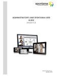
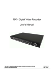
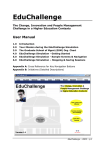
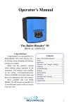
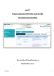
WCAN
COMNET III and LANPLANNER Solo Lab Exercises
Unit Guide
Wireless Communications
and Advanced Networks
(WCAN)
ECI-M-954
www.lsbu.ac.uk/bb
Blackboard access is through your username
and windows password
Faculty of Engineering,
Science and The Built
Environment
2009-2010
M
Become what you want to be
Sandra Dudley-McEvoy (UC)
Ya Bao
Wireless Communications and Advanced Networks Page 1
WCAN
COMNET III and LANPLANNER Solo Lab Exercises
Table of contents
1.
2.
3.
4.
4.1
4.2
4.3
4.4
5.
6.
7.
7.1
7.2
7.3
7.4
8.
9.
10.
10.1
10.2
11.
Section
Unit Details.........................................................................................4
Short Description............................................................................... 4
Aims of the Unit..................................................................................4
Learning Outcomes............................................................................4
Knowledge and Understanding ..........................................................4
Intellectual Skills.................................................................................4
Practical Skills ....................................................................................4
Transferable Skills..............................................................................4
Assessment of the Unit ......................................................................4
Feedback ...........................................................................................4
Introduction to Studying the Unit ………………………………………..4
Overview of the Main Content ............................................................5
Overview of Types of Classes............................................................5
Importance of Student Self-Managed Learning Time.........................5
Employability ......................................................................................5
The Programme of Teaching, Learning and Assessment ..................6
Student Evaluation ............................................................................8
Learning Resources ...........................................................................8
Core Materials....................................................................................8
Optional Materials ..............................................................................8
Course Work……………………………………………………………… 9
Laboratory Work
Appendix A: COMNET III…………………………………………………………..10
Appendix B: Motorola LANPLANNER Solo……………………………………….17
Sandra Dudley-McEvoy (UC)
Ya Bao
Wireless Communications and Advanced Networks Page 2
WCAN
COMNET III and LANPLANNER Solo Lab Exercises
1.0 UNIT DETAILS
Unit Title: Wireless Communications and
Advanced Networks
Unit Level: M
Unit Reference Number: ECI-M-954
Credit Value: 1
Student Study Hours: 150
Contact Hours: 60
Private Study Hours: 90
Pre-requisite Learning (If Data Communication Theory
applicable): Introduction to Data Communications
Course(s): MSc/PgDip TeCNE/IME
Year and Semester 2007 -2008, S2
Unit Coordinator: Dr. Sandra Dudley-McEvoy
UC Contact Details (Tel, Email, 020 78157124, [email protected]
Room) T711
Teaching Team & Contact Details Ya Bao,
020 78157588, [email protected]
T701
Subject Area: Electronics
Summary of Assessment Method: Exam + Coursework
2.0 SHORT DESCRIPTION OF THE UNIT
The unit covers the role of wireless technologies in current and future
data communications. A workshop is also part of this unit where you will be
required to design networks using simulation tools.
3.0 AIMS OF THE UNIT
This unit aims to extend your knowledge in data communications, wireless
communications, networks and protocols in the context of modern
telecommunications systems.
4.0 LEARNING OUTCOMES
The learning outcome may be measured according to the following three
criteria:
4.1 KNOWLEDGE AND UNDERSTANDING
•
You should by the end of this unit have knowledge and understanding
of wireless theory, methods and techniques: Standard specifications
and layered structures in communications. System design issues for
cellular system. Protocols and protocol architecture, high-speed LAN,
Sandra Dudley-McEvoy (UC)
Ya Bao
Wireless Communications and Advanced Networks Page 3
WCAN
COMNET III and LANPLANNER Solo Lab Exercises
VLAN VPN and network security. You should be able to identify and
appreciate the significance of the issues covered in the above topics.
4.2 INTELLECTUAL SKILLS
•
•
You should be able to make informed decisions on the appropriate
theory/methods/techniques required when faced with new technologies
and systems, e.g. VLAN, VPN, ATM, GSM, GPRS, UMTS and so on.
You should be able to simulate a simple network with COMNET III or
wireless LAN PLANNER Solo.
4.3 PRACTICAL SKILLS
•
•
Simulate and analyse networks both in wireless and non-wireless
environments.
Decide best case design for networks.
4.4 TRANSFERABLE SKILLS
•
•
•
The ability to work in a team
The ability to work out mathematical solutions from given problems
Competent report writing based on simulated assessments reports
5.0 ASSESMENT OF THE UNIT
•
•
There will be one 3-hour written examination worth 80%, a laboratory course
work worth 20% of the total unit marks.
You MUST submit your course work to faculty office (T313) before 1pm
Friday 9th May 2008. Late submission will be penalised in accordance with
the University regulation.
6.0 Feedback
Feedback will normally be given to students 15 working days after the
submission of an assignment.
7.0 INTRODUCTION TO STUDYING THE
UNIT
7.1 OVERVIEW OF THE MAIN CONTENT
This unit consists of 6 broad areas of study:
1). Wireless Communication Technology
2). Cellular System Design Fundamental
Sandra Dudley-McEvoy (UC)
Ya Bao
Wireless Communications and Advanced Networks Page 4
WCAN
COMNET III and LANPLANNER Solo Lab Exercises
3). Satellite Communication Systems
4). Network Simulation (Laboratory) covered from page 10
5). Wireless LAN’s
6). Advanced Data Networks
Each of the 6 areas is divided into specific study topics.
7.2 OVERVIEW OF TYPES OF CLASSES
These can be classified into three main activities as follows:
Lectures cover the basic material of the topics at a rate of 2 hours per week. You will
be given website based handouts to either accompany the unit textbook or to
complement it when necessary. You are encouraged to find out more about each topic
covered for deeper understanding, and to consult your lecturer for more information.
Tutorials will be at the rate of 2 hours per week. You will be given a website based
tutorial sheet when it is due. Prepare for the tutorial prior to the session to ensure
that you know how to apply the principles given in the lecture to practical problems.
Laboratory which will take 10 hours. You will be given website based lab sheets
when it due. Prepare for the exercises prior to the session to ensure that you
know how to use the software tool to simulate the network.
7.3 IMPORTANCE OF STUDENT SELFMANAGED LEARNING TIME
You may notice that this guide states that the unit requires 150 study hours, whereas
previous guides have defined each unit as 120 study hours. The University has made
this change in line with the way study time is likely to be expressed, in future, in the
majority of Universities. There is no change in teaching time, and no change in what
you are expected to do or achieve. The change concerns the way study time is
measured. Previously, the unit was defined as 120 hours work over 12 teaching
weeks. The new measure is still 10 hours per week over 15 weeks, including
assessment.
The workload for a full time student is still expected to be approximately 40 hours per
week.
7.4 EMPLOYABILITY
Wireless communication schemes are now considered the best way forward for many
countries when considering data transmission schemes ranging form personal area
networks, emergency situations and wide area networks. Knowledge of latest
technologies and their applications is essential for anyone wishing to work in the
telecoms industry.
Sandra Dudley-McEvoy (UC)
Ya Bao
Wireless Communications and Advanced Networks Page 5
WCAN
COMNET III and LANPLANNER Solo Lab Exercises
8.0 THE PROGRAMME OF TEACHING,
LEARNING AND ASSESSMENT
Study Area
Number of Weeks
1). Wireless Communication Technology
2
2). Cellular System Design Fundamental
4
3). Satellite Communication Systems
1
4). Network Simulation
1
5). Wireless LANS
3
6). Advanced Data Networks
2
7). Revision/Exam.
3
Now that we have equipped ourselves with the necessary tools and a time scale, we
can revert to our study areas.
1). Wireless Communication Technology
This part is concerned with the underlying technology of wireless transmission and
the encoding of analogue and digital data for wireless transmission. It exams the
fundamental principle of antenna and propagation, signal encoding techniques, spread
spectrum, coding techniques.
Learning outcome:
•
•
•
Define propagation modes, antenna gain, concept of spread spectrum and error
control schemes.
Understand the key issue of fading, principle of error control techniques.
Describe the general approaches of spread spectrum (FHSS, DSSS) and the
procedures of CDMA.
2). Cellular System Design Fundamental
This part covers fundamental cellular radio concepts such as frequency reuse and
handoff, which are at the core of providing wireless communication service to
subscribers on the move using limited radio spectrum. It also demonstrates the
principal of trunking efficiency, and how trunking and interference issues between
mobiles and base stations combine to affect the overall capacity of cellular systems.
This topic also provides an overview of third generation (UMTS).
Learning outcome:
•
Define concept of cellular, frequency reuse, channel assignment, handoff,
interference, system capacity, trunking, GOS, microcell.
Sandra Dudley-McEvoy (UC)
Ya Bao
Wireless Communications and Advanced Networks Page 6
WCAN
•
•
COMNET III and LANPLANNER Solo Lab Exercises
Understand, in detail, the advantages and design issues of cellular telephone
networks.
Know the advantages of the UMTS.
3). Satellite Communication Systems
This part covers the basic principles of satellite communications. It looks at
geostationary satellites (GEOs), low-earth orbiting satellites (LEOs), and mediumearth orbiting satellites (MEOs). The key design issue of capacity allocation is
examined in detail. Next-generation satellite networks will be discussed with
emphasis on bandwidth allocation protocols.
Learning outcome:
•
•
Understand and Evaluate satellite parameters and configurations.
Describe and analyse the capacity allocation schemes – FDMA, TDMA and
more advanced schemes.
4). Network Simulation
This year there are two network simulation packages for students to use.
(i) COMNET III is a performance analysis tool for communications networks. It is
used to model networks, their control algorithms, and workload. COMNET III then
simulates the operation of the network and provides measures of network
performance. Students can use COMNET III to model and simulate LANs, WANs,
and interconnections of various networks (internets).
(ii) LANPLANNER SOLO is a performance analysis tool for wireless communication
networks in buildings and on campus. It is used to model networks and access point
(AP) positioning within buildings previously designed in CAD or drawn by the user.
Students can use LANPLANNER SOLO to model and simulate WLAN’s.
Learning outcome:
• Know about simulation theories and methods.
• Can simulate several typical networks with COMNET III and LANPLANNER
Solo.
• Understand how to analyse the results given by COMNET III or
LANPLANNER SOLO reports.
5). Wireless LANS
This part provides a survey of wireless LANs.it covers an overview of principal types
of wireless LANs, Wi-Fi and the IEEE 802.11/16, Bluetooth and IEEE 802.15
standards
Learning outcome:
• Understand the WLANs classification according to transmission technology.
• Evaluate Wi-Fi, WiMax and the IEEE802.11 Standard.
Sandra Dudley-McEvoy (UC)
Ya Bao
Wireless Communications and Advanced Networks Page 7
WCAN
•
COMNET III and LANPLANNER Solo Lab Exercises
Explain and evaluate IEEE 802.15 standard with reference to Bluetooth and
comparison to 802.11/16 standards
6). Advanced Networks
This part provides a survey of high-speed networks including QoS provision and
congestion control issues. It will also introduce Gigabit Ethernet, VLANs (Virtual
Local Area Networks) and VPNs (Virtual Private Networks). These two newer
network technologies are quickly finding their way into businesses because of the
benefits they provide in terms of cost, flexibility, and security. This part will present
students with the basic concepts and issues involved in security, preparing them to
address these issues as they begin to design networks.
Learning outcome:
•
•
Understand traffic management, QoS provision and congestion control issues
in high-speed networks
Know the principle of VLANs and VPN, the basic concepts and issues
involved in network security.
8
9.0 STUDENT EVALUATION
Last years students overall were very happy with the unit.
10.0 LEARNING RESOURCES
10.1 CORE MATERIALS
1)
2)
Data and Computer Communications 7/E, by W. Stalling, Publisher: PrenticeHall, 2004. ISBN: 0-13-183311-1.
Wireless communications: principles & Practice 2/e, by Theodore S. Rappaport,
Publisher: Prentice Hall, 2002. ISBN: 0-13-040864-6.
10.2 OPTIONAL MATERIALS
1)
2)
3)
4)
5)
Introduction to Data Communications and Networking 4th and 5th Edition, by B.
Forouzan, Publisher: McGraw-Hill, 2001.
Wireless Communications and Networks, by W. Stalling, Publisher: PrenticeHall, 2002. ISBN: 0-13-040864-6
High-Speed Networks and Internets, by W. Stalling, Publisher: Prentice-Hall,
2002.
Mobile communications, by Schiller, Jochen H. Publisher: Addison- Wesley,
2000.
Satellite Communication Systems, B. G. Evans, Publisher: IEE Publishing, 1999.
Sandra Dudley-McEvoy (UC)
Ya Bao
Wireless Communications and Advanced Networks Page 8
WCAN
COMNET III and LANPLANNER Solo Lab Exercises
11.0 Course Work
You will be required to write a detailed formal report on a chosen network designed
by yourself using either COMNET III or LANPLANNER SOLO. You will be
required to submit the report to the faculty office (T313) by the final submission date,
1pm on the 7th of May 2010. Late submission will be penalised in accordance with the
University regulation.
Your report must includes
• Application or condition setting, (explanation)
• The topology of the network, (diagram and screenshot)
• Parameter setting of every block, (explanation)
• Traffic (message) configurations,
• Analyse and conclusion from the simulation results
Your report must not include the full original report generated by COMNET III or
LANPLANNER SOLO.
You can choices one of the following styles.
•
Design and simulate your self-designed networks using COMNET III or
LANPLANNER Solo. Present network design, characteristics, performance,
and conclusion.
The report should be 5-10 A4 sides and just be stapled together. Please do not submit
any plastic pages or covers with your report.
Sandra Dudley-McEvoy (UC)
Ya Bao
Wireless Communications and Advanced Networks Page 9
WCAN
COMNET III and LANPLANNER Solo Lab Exercises
Appendix A: COMNET III
1. Introduction
COMNET III is a performance analysis tool for computer and communication networks. Based
on a description of a network, its control algorithms and workload, COMNET III simulates the
operation of the network and provides measures of network performance. No programming is
required. Network descriptions are created graphically through a highly intuitive interface that
speeds model formulation and experimentation.
COMNET III is integrated into a single windowed package which performs all functions of
model design, model execution and presentation of results. A model is built and executed in
several straightforward steps:
•
Nodes, links and traffic sources are selected from a palette and dragged into position on
the screen. An option to automatically import the topology from Network Management
Systems such as OpenView, NetView, and Spectrum is available.
•
These elements are connected (using the connection tool) to define their
interrelationships.
•
The user double clicks on one of the nodes, links or traffic sources. A dialog box with all
adjustable parameters appears and the user specifies the parameters for this particular
item.
•
Network operation and protocol parameters are set on additional dialog boxes accessed
through the menu bar.
•
The model is verified and executed, after which the results are presented in various
reports.
2. Applicability
COMNET III can be used to model both Wide Area Networks (WANs) and Local Area
Networks (LANs). COMNET III models may contain both types of facilities in one integrated
model. COMNET III can also provide detailed modelling of network node logic. A node’s
computers, their I/O subsystems, their databases and the applications which run on the
computers can all be modelled.
By using discrete event simulation methodology, COMNET III provides realistic and accurate
results. The alternative to discrete event simulation is to use traditional mathematically based
analytical methods which cannot cope with the effects of random variance. The simplifying
assumptions required by analytical methods ignore the effects of queuing, event interdependence
and random variance when analyzing complex communication networks.
The network modelling approach used in COMNET III is designed to accommodate a wide
variety of network topologies and routing algorithms. These include:
Sandra Dudley-McEvoy (UC)
Ya Bao
Wireless Communications and Advanced Networks Page 10
WCAN
•
•
•
•
COMNET III and LANPLANNER Solo Lab Exercises
LAN, WAN & Internetworking systems
Circuit, message and packet switching networks
Connection-oriented and connectionless traffic
Static, adaptive and user-defined algorithms
A significant new feature of COMNET III is the ability to abstract portions of a network model
and treat them as modular components. This capability follows from the object-oriented design
of COMNET III. This new facility also allows the user to build a library of network device
components which can be “plugged in” and swapped at will.
3. Overall Approach
COMNET III is designed to accurately estimate the performance characteristics of computing
and communication networks.
Estimating means that the network under study is described to COMNET III via data. COMNET
III then executes a dynamic simulation of the network which builds a computer representation of
the network and routes simulated traffic over it. Reports are produced on the measured
performance of the different model elements and overall network characteristics, and are
presented as the estimations of network performance.
This data, which is entered via a graphical user interface, describes:
•
The topology of the network: nodes, computer centres, connectivity, etc.
•
The workload placed on the network. This includes the applications that run on end
systems and the traffic to be delivered across the network. The frequency and size of
different tasks may be described statistically.
•
The protocols or rules for scheduling applications and routing traffic.
The reports produced are an estimate of the expected performance of the real network. Their
accuracy is dependent on the data that has been entered to describe the network. One of the
major questions is how accurate is the data and consequently how accurate are the estimates of
performance.
Another factor which determines accuracy is the run-length or amount of simulation time the
model is run. The length of the run determines how many random events are used to represent
the statistically generated traffic. For instance, you may specify that file transfers are to be
modelled, and that the file sizes are randomly picked between 10KB and 50KB. If you only run
the model long enough to represent 5 file transfers then the file sizes might be 37KB, 21KB,
17KB, 11KB, 31KB which gives an average file transfer of 23.4KB versus an expected average
of 30KB. However, if you run the model longer and obtain results over 1,000 file transfers, then
the average file transfer size will converge on the expected average.
With run length in mind, the accuracy of the results of a simulation are normally quantified with
a variation and a statistical confidence estimate. For instance, file transfers are completed with
an average delay of 10.5 seconds with an observed standard deviation of 2.3 seconds and with a
95% confidence of statistical correctness.
Sandra Dudley-McEvoy (UC)
Ya Bao
Wireless Communications and Advanced Networks Page 11
WCAN
COMNET III and LANPLANNER Solo Lab Exercises
COMNET III can run multiple, independent replications of the simulation and generate mean,
maximum, minimum and standard deviations, as well as plots and histograms of system
performance. We recommend Simulation Modeling & Analysis (Averill M. Law, W. David
Kelton. 2nd ed. New York: McGraw-Hill, 1991) for a full discussion on the statistical treatment
of simulation experiments.
Once you have built a model which produces accurate estimates of the performance of your
network, you can then use the model for a variety of “what if” experiments. These are discussed
below.
4. Uses of COMNET III
Typical COMNET III applications include:
•
Peak Loading Studies
Generally a network is subject to heavy levels of traffic at particular times of the day,
week, month or year. If the network design can cope with this level of traffic then it can
cope with the workload during other periods. The typical use of COMNET III is
therefore to model these peak loading periods to gain an understanding of the stress
points in the network.
•
Network sizing at the design stage
When designing a new network some provision for growth must be allowed for.
COMNET III can be used to assess that the design meets current traffic levels, and it can
be used to see what room there is in the design for system growth.
•
Resilience & contingency planning
It is often important to know that a network design has sufficient resilience to offer a
reasonable level of performance in various failure scenarios. The nodes and link
components in a COMNET III model can be failed and recovered at various times in the
simulation to test various contingencies that are not testable in the real system.
•
Introduction of new users/applications
New users and/or applications will typically add more load onto the network. It is useful
to try and predict their impact before their introduction so that potential bottlenecks can
be identified and resolved before a major problem appears
•
Evaluating performance improvement options
Many networks have year on year traffic growth. This results in deteriorating network
performance until the network is upgraded in some way. The various options for
upgrading can be investigated in COMNET III as part of a cost vs. benefit study.
•
Evaluating grade of service contracts
It is increasingly common practice for service level contracts to be negotiated between
the network user and the network provider, even when they are part of the same
organization. COMNET III can be used to analyze the performance service levels that
can be attained during contract negotiation, and to predict potential problem areas as
usage patterns of network components change over time.
Sandra Dudley-McEvoy (UC)
Ya Bao
Wireless Communications and Advanced Networks Page 12
WCAN
COMNET III and LANPLANNER Solo Lab Exercises
Experiment 1: Building a Simple Model
We will now build a very simple model of a network. It will have two nodes, two message
traffic generators, and two links to carry the traffic. The diagram below shows how the model
should appear once we have completed the layout:
Simple Model Layout
Start COMNET III and choose File/New.
The palette on the left-hand side of the screen allows you to create the various objects that are
needed. A diagram of the palette is shown here.
Sandra Dudley-McEvoy (UC)
Ya Bao
Wireless Communications and Advanced Networks Page 13
WCAN
COMNET III and LANPLANNER Solo Lab Exercises
Start by clicking on the Processing node tool of the tool palette. Click on the layout screen to
create a node icon. Repeat the action to place a second node on the screen. Leave room for the
links between them. To adjust their positions, choose the selection tool at the top left of the tool
palette and then click on any object and drag it to a new position while holding the mouse button
down.
Rename the nodes to more descriptive names, such as LA and NY
Click on the point-to-point link tool of the tool palette and then click between the two nodes to
create and position a new link. Repeat this for the second link.
Click on the message source tool of the tool palette and place one message source adjacent to
each node.
Connect the objects together using connection arcs.
Click once on an object, then once on its neighbour, to place a connection arc between them.
Go back to the selection mode and double-click on each icon in turn. As you double-click on the
icon a dialog box appears which allows you to specify details on the represented object. Give
each object the appropriate name.
On the message sources, change the default Interarrival time for messages from an
Exponential distribution with a Mean of 10 seconds to an Exponential distribution
with a Mean of 30 seconds. This can be accomplished by clicking on the button with 2 dots
next to the Interarrival time and then typing 30 into the Mean value box.
Sandra Dudley-McEvoy (UC)
Ya Bao
Wireless Communications and Advanced Networks Page 14
WCAN
COMNET III and LANPLANNER Solo Lab Exercises
Next, set the packet routing algorithm for the backbone network to User Defined
Routing Tables (there are no subnetworks in this model). This can be accomplished by
picking the Define/Backbone Properties menu option and then clicking on the down
arrow of the Packet routing protocol list box to see the choice of routing algorithms. Pick
User Defined Routing Tables. We will shortly set two alternate routes between the two
nodes. We need to tell COMNET III how to choose between them. Click on the ‘… ’ button
next to the packet routing protocol and set the Primary route selection rule to Random
list. This will cause traffic to be randomly routed over the different routes, thus resulting in a
balanced load sharing mode of operation. Click on OK on each dialog box to get back to the
layout screen.
Define the routes in the table. Pick the LA node by double-clicking on it and bringing up its
dialog box. Select the Routing Tables tab and then click on the Packets routing table
button. You are then presented with the following dialog box.
This dialog box shows that we have a possible destination of NY and the number of routes we
have defined to get there (initially this is 0). Click on the field showing the number of routes to
highlight it, and then click on the Edit Selected button. The Edit Routes dialog box appears
which is used to define the routes that will appear.
From the bottom-right list pick LinkA and then pick the Add TO End button underneath the
top-right list box. Underneath the top-left list box pick the Add To End button.
From the lower-right list box pick LinkB, and then add it to the end of the route as before. This
then completes the second route. Click OK on this dialog box to return to the outer dialog box,
and the OK again to return to the layout screen.
Sandra Dudley-McEvoy (UC)
Ya Bao
Wireless Communications and Advanced Networks Page 15
WCAN
COMNET III and LANPLANNER Solo Lab Exercises
Go through the same process to set up routes from NY to LA.
We now need to specify how long to run the simulation. Pick the Simulate/Run
Parameters screen and change the Replication length to 1 hour (3600 seconds). Then
click OK.
Now pick Reports/Select Reports and go to Message & Response Sources. Next,
select each report category: Message Delay, Message Delivered, and Packet Delay
and Set All button to turn all of these reports on.
To save this model, choose File/Save As. Then type in the name of the model in the file
name box. Do not add the . c 3 extension; COMNET Ill will add it.
Now select Simulate /Trace and tick Trace to screen off to quicken the progress.
Sandra Dudley-McEvoy (UC)
Ya Bao
Wireless Communications and Advanced Networks Page 16
WCAN
COMNET III and LANPLANNER Solo Lab Exercises
When the simulation completes you can use the Report/Browse Reports menu option to
review the results. Refer to the Statistics and Reports Manual (
http://eent3.sbu.ac.uk/staff/baoyb/acs/ ) for further information on how to read these report.
References:
COMNET III Reference Guide
COMNET III Getting Started Guide
Experiment 2: Local Area Networks
Objective:
Set up a simple one server Ethernet LAN in COMNET III and observe simulation result. Student
will run several simulations using several different message distribution settings as well as
changing the number of the computers in a LAN to help student observe the effect of message
size distribution and number of computers on the network performance. Students are expected to
have some basic knowledge about the COMNET III. The results of these simulation will be used
by the students to come up with conclusions about the effect of above mentioned changes on the
network performances.
Procedures:
You will set up a simple one server Ethernet LAN in COMNET III. The number of the computer
clients in this network will also vary. This lab will simulate the network interaction between
computer group (clients) and the server. The transaction of the information will be as follows:
first, the message request will be generated by the computer groups. When the server receives
the request it replies back to the computer group. Note: the inter-arrival parameter will NOT
change between separate simulations on this lab. The only parameters that will be changed are
message size calculation and the number of the computers in the group. Use the following set up
parameters:
•
•
•
•
•
One Server (Icon on the left side 3rd down from the top).
One Computer Group (Icon right of the server icon). You may change the number of the
computers in the computer group by double-clicking the computer group icon.
One Ethernet Link; the network type is 10 Mbps Ethernet (8Th Icon down the left hand
side).
One Message Source (9th Icon down on the left hand side).
One Response Source (Icon right of Message Source Icon).
Select Link and set the speed of the networks to be 10M bit/s (if you select 10BaseT, the speed
is set for you automatically to 10Mbit/s). and Choose the type of the network to be 10baseT.
Select the computer group and set the number of computer to 1.
You will have on the computer screen total of 5 different Icons. The number of icons on the
COMNET desktop will remain 5 throughout this lab (i.e. all simulations 1 through 10 will have
5 icons).
Sandra Dudley-McEvoy (UC)
Ya Bao
Wireless Communications and Advanced Networks Page 17
WCAN
COMNET III and LANPLANNER Solo Lab Exercises
Now connect the network so the simulation can begin:
1. Connect Computer Group and Server to the Ethernet Link.
2. Connect message source to the Computer Group.
3. Connect Response Source to the Server.
Now, names of the server and computer groups must be defined.
1. Select the server
2. Change the name to "Server_1"
3. Select the computer group and change the name to "Computers"
Now, the message source and the response source must be configured. Select the message
source via mouse click. And configure the setting to following:
1.
2.
3.
4.
5.
6.
7.
Set the Name to "Message Request"
Set Interarrival to "Uni(1,7,2)"
Set Prob distrib to "Uni(10000,20000,3)
Dest Type must be set at "Random list"
Triggered Sources must not have any entries.
Edit Destination List… must have name of the server in our case "Server_1".
Priority = 1, Routing class = standard, Trans protocol = Generic, Packetize = 1, Msg size
units = Bytes.
Now, the Response Source must be configured.
1. Set the Name to "Message Response"
2. Set Prob distrib to "Uni(10000,20000,4) Msg size cal should be set to Probability
distribution.
3. "ECHO" in report must not be checked. The report will still have ‘echo’ section in the
report, but these will all have value of zero.
4. Triggered Sources must not have any entries; must be left blank.
5. Msg text option… must be Copy message name.
6. Priority = 1, Routing class = standard, Trans protocol = Generic, Packetize = 1, Msg size
units = Bytes.
Now, you are set to setup simulation run parameters: On your own set the simulation
parameters as following:
1.
2.
3.
4.
5.
Set warm up time to 10 seconds
Set Replication Length to 300 seconds
Set animation to off.
Select report name as "Lab_1b" or any other unique name you wish.
Select following under the report options: (For example, Received message count is
under Node, i.e. expand Node to see further options).
• Node: Received message count = on
• Link: Channel utilization = on
• Message + Response Source report: both Message delay and Packet Delay = on.
• Above are the minimum requirements; you may wish to select other reports to be
on.
Sandra Dudley-McEvoy (UC)
Ya Bao
Wireless Communications and Advanced Networks Page 18
WCAN
COMNET III and LANPLANNER Solo Lab Exercises
Simulation
Now we are ready to run the simulation. The objective of this lab is to vary both message size
distribution and the number of computers on the network and observe its effect on the network.
Appendix B: LANPLANNER Solo
1. Introduction
LANPLANNER SOLO is a software package that allows you to efficiently design, model and
measure 802.11a, 802.11b and 802.11g wireless networks. Building facilities and campus
environments can be quickly modelled using menus that guide you step by step. You can
quickly place access points (AP) and predict signal coverage during the WLAN design phase.
For post-WLAN deployment, you can use LANPLANNER SOLO’s powerful features for
measuringnetwork performance and validating
2. Understanding Wireless Network Design
Some general knowledge is important for designing a wireless communications network using
802.11a, b, or g technologies. By no means is this section meant to be complete or
comprehensive, but it should serve as a general introduction for someone who has limited
knowledge of designing and deploying wireless networks.
3. Wireless Network Basics
Designing a WLAN and deploying an access point can be a relatively easy task, but problems
hindering the quality of the network quickly multiply when multiple access points are involved.
The proximity of access points to users and to each other, access point channel settings, and
access point power settings can all affect the performance of the wireless network. Most people
consider application level throughput to be a good indicator of network performance. There are
many factors that contribute to the performance of a wireless network; however, two metrics are
usually considered in wireless designs to ensure that an acceptable level of throughput is
obtained in desired coverage areas: signal strength and interference.
Several important factors directly affect signal strength. Signal strength near an access point
(same room to several tens of feet away) is considered very strong and is directly related to the
access point’s output power level. Signal strength, however, decreases as you move farther away
from the access point (referred to as attenuation). Another key factor that contributes to
diminished signal strength are obstructions, such as walls and wall-like metal shelving. In
general, it is safe to ignore obstructions such as people and furniture when modelling a facility
for signal coverage because their overall affect on signal strength is minimal. Keep in mind that
different construction materials attenuate RF signal in different ways. RF interference can also
affect application level throughput. RF interference occurs when radio signals transmitted on
overlapping frequency ranges (or channels) cause a distortion in the radio wave pattern. Two
access points that operate on the same channel and within close proximity of each other cause
interference when transmitting at the same time. Beware that 802.11b and 802.11g use the same
frequency range and can be affected by common items such as microwaves and cordless
telephones.
Sandra Dudley-McEvoy (UC)
Ya Bao
Wireless Communications and Advanced Networks Page 19
WCAN
COMNET III and LANPLANNER Solo Lab Exercises
4. Site Modelling - Create Site-Specific Information
The first step in wireless network design is to model the facility or facilities that will be
considered for wireless coverage. LANPlanner Solo requires a specially formatted drawing file
that properly represents the building obstructions that may significantly affect RF signal
coverage. The drawing file contains information about the location of walls and other
obstructions, and the type of construction material. The LANPlanner Solo Format Building
menu (See “Modeling a Building” on page 63) provides powerful functionality for modeling
your building or campus quickly and easily. The Format Building menu supports three basic
“starting points” for generating the three-dimensional drawing of a facility.
• Start with a previously drawn CAD file.
• Start with a scanned image
• Start with a basic concept of the facility layout (requires free-hand sketch of the facility)
Most large building facilities are designed in a CAD (Computer Aided Design) software
package. There are many different CAD file formats, but one of the most common is the .dwg
and the .dxf file formats. LANPlanner Solo supports importing CAD files of this format directly.
If you can obtain the CAD files for your facility, this makes a great starting place for modelling
the building. Another convenient option is to simply obtain a sketch of the drawing facility from
either a blueprint, fire escape exit map, or an aerial photo (if modelling a campus environment).
LANPlanner Solo supports importing many common image formats such as bitmaps. If you are
unable to obtain a computer file containing information about your campus or building facility,
then LANPlanner Solo allows you to sketch a diagram of the building facility. This option will
most likely require that you have either visited the facility, been told its basic structure, or
previously seen a diagram of the facility. LANPlanner Solo does not require that every facility
wall or obstruction be modelled to 100% accuracy, but the accuracy of the software’s predictive
engine depends on the modelled facility. It is important to model any major obstructions and the
general location and scale of building walls in order for the predictive engine to produce useful
results.
5. Design - Hardware Placement and Prediction
After you have modeled your building or campus environment using LANPlanner Solo’s
Building Wizard, you are ready to begin designing the wireless network. Designing the wireless
network involves using the functionality provided by the Network Design menu. The design
step includes:
• Selecting wireless access points and sensors
• Placing the access points and sensors
• Predicting and visualizing wireless signal coverage
• Generate a comprehensive Bill of Materials (BOM) of all wireless equipment in your design
LANPlanner Solo allows you to model every important aspect of your system design so that it
can predict the network’s performance as accurately as possible. Using the Network Design
menu is described in Chapter 5 of the pdf help file.
6. Deployment - Verifying Your Design
After deploying your wireless network, you can use Network Verification within LANPlanner
Solo to help verify signal coverage and optimize your building model. Post-deployment signal
coverage verification is beneficial for one or more of the following reasons:
Sandra Dudley-McEvoy (UC)
Ya Bao
Wireless Communications and Advanced Networks Page 20
WCAN
COMNET III and LANPLANNER Solo Lab Exercises
• Informs you of potential flaws in your original design by determining if the network performs
as originally predicted.
• Provides LANPlanner Solo with building model RF characteristics that can be archived for
modifying future designs in the same building, or other buildings of similar construction.
• Enables building model optimization and wireless network fine-tuning.
• Documents the quality of the network as originally installed.
Wireless network verification and optimization is performed using the Network Verification
menu, which is described in the pdf help file Chapter 6.
References
Motorola LANPLANNER Solo
Example 1. Introduction of the LANPlanner® Solo
LANPlanner Solo is a revolutionary software package that enables you to efficiently design,
model, and measure 802.11a, 802.11b, and 802.11g networks. Building facilities and campus
environments can be quickly modelled using menus that guide you step-by-step. You can
quickly place access points and predict signal coverage during the WLAN design phase. PostWLAN deployment, you can use LANPlanner Solo’s powerful features for measuring network
performance and validating network designs.
1. Launch LANPlanner Solo by double-clicking the LANPlanner Solo
from your Windows desktop:
icon
When the LANPlanner Solo GUI opens, note the major features
Toolbar Icons
Sandra Dudley-McEvoy (UC)
Ya Bao
Wireless Communications and Advanced Networks Page 21
WCAN
COMNET III and LANPLANNER Solo Lab Exercises
2. Opening an Existing Workspace
You may use the File >Open Drawing command to open a drawing file
Default_final_with_key located at Default Folder. Then Click NO on the promoted window.
A 4 floor building drawing is shown in the window as below.
Note: Never save any your own works in the Default folder. Save everything on your OWN
disk.
3. Access Point Placement
Single left click on it. Then double click on the
802.11g in the next prompted window.
You can directly place Access Points at desired
locations in the drawing by clicking in the drawing
at the locations you want to locate the hard wares.
Right click and select Done to finish the placement.
Sandra Dudley-McEvoy (UC)
Ya Bao
Wireless Communications and Advanced Networks Page 22
WCAN
COMNET III and LANPLANNER Solo Lab Exercises
4. Quick Prediction
Click on Quick Prediction button on the toolbar.
The following window will prompted. You can start from the Grid Predictions.
Click on Next>>>,
Multi-select all APs, click OK.
The predicted results will be shown as below.
Sandra Dudley-McEvoy (UC)
Ya Bao
Wireless Communications and Advanced Networks Page 23
WCAN
COMNET III and LANPLANNER Solo Lab Exercises
You can click on the Cancel Prediction to cancel the prediction.
5. Try other selections on the prediction window to familiarise yourself.
6. Try all selections on the prediction window on floors 03, 02 and 01.
7. Try to move the position of the APs, predict the results.
8. Save your work on your OWN USB stick.
Reference:
LanPlanner, User’s Manual. 1/6/2006, Motorola, INC.
Example 2. Quick Start AP Planning by LanPlanner® Solo
LANPlanner Solo includes the ability to automatically place and configure Access Points (APs)
in the building model to satisfy your unique coverage and capacity requirements.
1. Selecting Network Design > Quick Start AP Placement opens the Select
Access Point Model dialog. Choose 802.11g then Next>>>.
Sandra Dudley-McEvoy (UC)
Ya Bao
Wireless Communications and Advanced Networks Page 24
WCAN
COMNET III and LANPLANNER Solo Lab Exercises
Global Auto-Placement Options window applies to all access point requirement regions
specified during the auto-placement process.
2. Specify Client Location and Requirement Regions
You can create multiple regions with each region specifying unique coverage, capacity (data
rate), and the number of users. The Quick Start algorithm satisfies two different metrics:
• Coverage - Guaranteed data rate (peak data rate) across the requirement region, such that
each user in that region can connect at that data rate. Data rate is mapped directly from
the RSSI (signal strength).
• Capacity - Number of users multiplied by average usage per user (called avg. data rate)
such that enough access points are placed to satisfy the usage requirements.
If you are working with a drawing that has multiple floors, select the floor from the drop-down
box. The Quick Start placement wizard can optimise access point placements for requirement
regions defined on multiple floors at once. The requirement region list shows all regions in the
drawing, not just for the current floor.
3. Create the new region in the building drawing by selecting Create New Region. Left-click
once to begin the region and again to specify the end point.
Sandra Dudley-McEvoy (UC)
Ya Bao
Wireless Communications and Advanced Networks Page 25
WCAN
COMNET III and LANPLANNER Solo Lab Exercises
4. Specifying Exclusion Regions
Sometimes the designer may need to identify areas in a building that equipment cannot be
placed in. These areas, know as exclusion regions, can be specified so that LANPlanner Solo
will not place any access points within them. The equipment exclusion region window is shown
below. Click Done to execute Quick Start AP Placement with your settings.
LANPlanner Solo’s placement engine then:
• Chooses optimal locations for the access points to satisfy coverage and capacity
requirements
• Determines optimal channel assignments to maximize SIR (Signal-to-Interference
Ratio), and sets the channel on each access point appropriately
• Optimises and configures power levels, effectively reducing the power of access points
from the initial power setting
Sandra Dudley-McEvoy (UC)
Ya Bao
Wireless Communications and Advanced Networks Page 26
WCAN
COMNET III and LANPLANNER Solo Lab Exercises
•
Takes floor-to-floor signal into consideration and also takes into account access points
which already exist in the current drawing.
After executing Quick Start AP Placement, LANPlanner Solo updates the drawing window with
the placed access points and signal coverage contour as above figure.
Once you are satisfied with access point placement, you are ready to evaluate the design in detail
and reconfigure hardware as needed.
5. Edit/Remove Access Point
The Network Design > Edit/Remove Access Point command allows you to edit, remove,
move, or copy any access point in the drawing. From the Move Access Point dialog, select the
access point that you wish to move and click Move.
Your pointer will take on the appearance of the access point that you selected from the list.
Move the Access Point to the desired location and click to place it. Click Finished after moving
access points.
6. Managing Sensors
Placing Sensors
Sensors are RF detectors used in a wireless network designs to monitor RF activity in your
network environment. This feature is a key enabler for wireless asset tracking. LANPlanner Solo
allows you to place sensors within your building drawing. To do this, select Network Design >
Sensor > Place Sensor.
you can edit and remove sensors from your building drawing by selecting
Network Design > Sensor > Edit/Remove Sensor.
7. Running Quick Prediction
Predict performances of this wireless network.
8. Save your work on your OWN USB stick.
Exercises:
Open the original existing drawing: Default_final_with_key,
1. Use 6 Access Points (802.11g) to cover floor 2 to provide a wireless coverage as a high
rate as possible. Give out the performance predictions.
Sandra Dudley-McEvoy (UC)
Ya Bao
Wireless Communications and Advanced Networks Page 27
WCAN
COMNET III and LANPLANNER Solo Lab Exercises
2. Provide a 36 Mbps wireless coverage on floor 2 with numbers of Access points
(802.11g) as less as possible. Show the performance predictions.
Reference:
LanPlanner, User’s Manual. 1/6/2006, Motorola, INC.
Sandra Dudley-McEvoy (UC)
Ya Bao
Wireless Communications and Advanced Networks Page 28