1
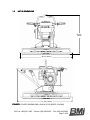
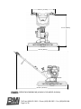
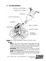
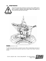
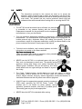
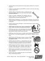
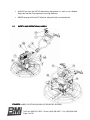
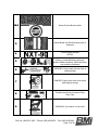
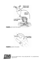
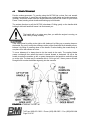
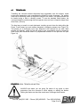
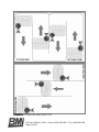
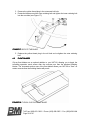
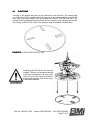
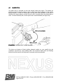
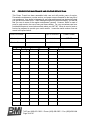
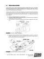
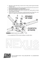
POWER TROWEL
Model:
Model: NXTNXT-90
Operator’s Manual
ORIGINAL LANGUAGE
Document #:
Created Date:
Revision:
Revision Date:
NEX-0001
01/2008
1
08/2009
OI-N09101
Bartell Morrison Inc.
375 Annagem Blvd.
Mississauga, Ontario, Canada
L5T 3A7
Toll Free (N.A.):
Phone:
Facsimile:
(866) 501-1683
(905) 458-5455
(905) 458-5484
ORIGINAL LANGUAGE OPERATING INSTRUCTIONS FOR
NEXUS WALK-BEHIND POWER TROWELS © 2008 BY
BARTELL MORRISON INC.
ALL RIGHTS RESERVED.
No part of this work may be reproduced or transmitted in any
form or by any means, electronic or mechanical, including
photocopying and recording, or by any information storage or
retrieval system without the prior written permission of Bartell
Morrison Inc. unless such copying is permitted by federal
copyright laws.
Address inquiries or reference permissions care of:
Bartell Morrison Inc., 375 Annagem Blvd., Mississauga,
Ontario, Canada, L5T 3A7
Revision
0
1
Rev. Date
01-31-2008
08-17-2009
Details
Initial document release
Relocation
Approved
G.M.T.
D.M.
Toll Free: (866) 501-1683 / Phone: (905) 458-5455 / Fax: (905) 458-5484
Page 2 of 38
TABLE OF CONTENTS:
PRODUCT SAFETY
5
1.0 MEET THE NEXUS NXTNXT-90 POWER TROWEL
1.1 EQUIPMENT USE AND CARE
1.2 SAFETY FEATURES
1.3 NXT-90 DIMENSIONS
1.4 NXT-90 MAIN COMPONENTS
1.5 LIFTING THE NXT-90
6
6
6
7
9
11
2.0 SAFETY
2.1 SAFETY AND OPERATIONAL LABELS
2.2 DOUBLE-DEADMAN SAFETY HANDLE
12
14
17
3.0 SETTING UP THE NXTNXT-90
3.1 USING THE FOLDING HANDLE
3.2 STARTING THE NXT-90
18
18
21
4.0 TROWEL TECHNIQUE
4.1 TROWELLING
4.2 POWER TROWEL BLADES
4.3 FLOAT BLADES
4.4 FLOAT PANS
4.5 BLADE PITCH
22
23
25
26
27
28
5.0 STORAGE AND SERVICE
5.1 PREVENTATIVE MAINTENANCE AND ROUTINE SERVICE
5.2 ROUTINE SERVICE INTERVALS
5.3 STORAGE
5.4 TROWEL ARM ADJUSTMENT
29
30
32
32
33
CE DECLARATION OF CONFORMITY
NOTES
36
38
TABLE OF ILLUSTRATIONS & FIGURES
FIGURE
FIGURE 1: FOLDED DIMENSIONS. . . . . . .
FIGURE 2: OPERATING DIMENSIONS. . . .
FIGURE 3: MAJOR COMPONENTS. . . . . . .
FIGURE 4: PROPER LIFTING. . . . . . . . . . .
FIGURE 5: LABEL LOCATIONS. . . . . . . . . .
FIGURE 6: DEADMAN HANDLE OPER. . . .
FIGURE 7: FOLDED HANDLE FEATURES.
FIGURE 8: UNLOCKING THE BAR. . . . . . .
FIGURE 9: UNFOLDING THE HANDLE. . . .
FIGURE 10: HANDLE LOCK KNOB. . . . . . .
FIGURE 11: PULL-STARTING THE NXT-90
FIGURE 12: STEERING THE NXT-90. . . . .
PG.
7
8
9
11
14
17
18
19
20
20
21
22
FIGURE
FIGURE 13: IDEAL TROWELLING MOTION.
FIGURE 14: TROWELLING PASS DIR. . . . .
FIGURE 15: TYPICAL FINISHING BLADE. .
FIGURE 16: LOOSEN RETAINING BOLTS. .
FIGURE 17: ROTATE THE BLADE. . . . . . . .
FIGURE 18: TYPICAL FLOAT BLADE. . . . . .
FIGURE 19: TYPICAL FLOAT PAN. . . . . . . .
FIGURE 20: PITCHING THE BLADES. . . . . .
FIGURE 21: TROWEL ARM LIFT ASSY. . . .
FIGURE 22: ARM ADJUSTMENT FIXTURE.
FIGURE 23: SPIDER ASSY OIL BATH FILL.
Toll Free: (866) 501-1683 / Phone: (905) 458-5455 / Fax: (905) 458-5484
Page 3 of 38
PG.
23
24
25
25
26
26
27
28
33
33
34
This page intentionally left blank
Toll Free: (866) 501-1683 / Phone: (905) 458-5455 / Fax: (905) 458-5484
Page 4 of 38
PRODUCT SAFETY
READ OPERATING
OPERATING INSTRUCTIONS
Read and understand this entire manual before attempting
operate or service the equipment described herein. Failure
follow these operating instructions could result in serious injury
death. Store this manual with the machine and ensure it
apparent and available to any users.
to
to
or
is
CALIFORNIA PROPOSITION 65 WARNING
Engine exhaust, some of its constituents, and certain vehicle
components, contain or emit chemicals known to the State of
California to cause cancer and birth defects or other reproductive
harm.
PRODUCT SAFETY AND HAZARD ALERT SYSTEM:
This Operating Manual presents Product Safety and Hazard Alert Information in
accordance with American National Standards Institute and International Organization for
Standardization recommendations as laid out in ANSI Z535 and ISO 3864. The callouts of
DANGER, WARNING, CAUTION, and NOTE must be followed to reduce or avoid the
potential for personal injury, equipment damage, or service-related equipment failures.
Safety Hazard Alert:
Alert:
Alerts the reader to
personal injury hazards
and
other
important,
potentially
life-saving
information.
DANGER:
Beware of a hazardous
situation that WILL result in
serious personal injury or
death.
WARNING:
Beware of a hazardous
situation that COULD
result in serious personal
injury or even death.
CAUTION:
Beware of a hazardous
situation that could result in
minor personal injury or
equipment damage.
Toll Free: (866) 501-1683 / Phone: (905) 458-5455 / Fax: (905) 458-5484
Page 5 of 38
1.0
MEET THE
THE NEXUS NXTNXT-90 POWER TROWEL
The equipment depicted in these instructions is a pedestrian controlled, gasoline engine
powered assembly including a rotor on which blades are attached that contact an uncured
concrete surface. The rotor turns around a central shaft when under power and is
supported through a worm gear speed reducer. For control of this assembly a handle is
provided for the operator to grasp and manipulate the travel of the machine on the
concrete surface. The assembly includes safety devices in accordance with North
American and International standards.
1.1
EQUIPMENT USE AND CARE
The Nexus NXT-90 Power Trowel is designed for use on uncured concrete. It should be
operated at all times in accordance with the instructions detailed in this manual:
•
•
•
Use of this equipment for any purpose other than that stated within creates the risk
of personal injury and/or property damage.
Any modifications to the equipment must be performed by the manufacturer or an
authorized dealer and must be authorized in advance by the manufacturer.
The equipment should be serviced, cleaned, and stored as detailed by this manual.
The manufacturer of this equipment cannot be held responsible for any damages resulting
from misuse, abuse, or neglect.
1.2
SAFETY FEATURES
The Nexus NXT-90 Power Trowel is equipped with safety guards in accordance with North
American and International standards. The main safety ring protects the blades from
collisions with solid objects, but more importantly protects the operator from the blades.
The belt guard protects the operator from the main drive belt. The handle is equipped with
a “double-deadman” operator presence system as standard equipment. The use and
function of this system is covered in the next section.
NEVER attempt to disable or circumvent these safety devices. They are
present for the operator’s protection and any tampering will result in
substantial risk to the operator and all present at the job site. If your NXT90 safety devices have been tampered with, do not use the Power Trowel.
Immediately contact your sales representative to obtain replacement parts
or return the trowel to your dealer for repairs.
Toll Free: (866) 501-1683 / Phone: (905) 458-5455 / Fax: (905) 458-5484
Page 6 of 38
1.3
NXTNXT-90 DIMENSIONS
27-5/8”
(70cm)
38-3/4” (98cm)
41-3/8” (105cm)
FIGURE 1: FOLDED DIMENSIONS (HONDA GC160 MODEL SHOWN)
Toll Free: (866) 501-1683 / Phone: (905) 458-5455 / Fax: (905) 458-5484
Page 7 of 38
28-1/8” (71.5cm)
37-1/2” (95cm)
38-3/4” (98cm)
64-3/8” (163.5cm)
FIGURE 2: OPERATING DIMENSIONS (HONDA GC160 MODEL SHOWN)
Toll Free: (866) 501-1683 / Phone: (905) 458-5455 / Fax: (905) 458-5484
Page 8 of 38
1.4
NXTNXT-90 MAIN COMPONENTS
FIGURE 3: NXT-90 MAJOR COMPONENTS (HONDA GC160 MODEL SHOWN)
•
Drivetrain:
o
Engine: The NXT-90 Power Trowel is available with three engine options: Briggs
& Stratton Vanguard 6.5HP, Honda GC160, and Honda GX160. The engine
warranty is provided by the manufacturer. For more details please refer to the
engine manual included with your NXT-90. Missing manuals can be replaced by
your equipment manufacturer directly or via your local dealer.
o
Clutch and Belt: The engine of the NXT-90 drives a centrifugal clutch, allowing
the engine to idle without turning the spider. The drive belt, when engaged with
the clutch, drives the gearbox pulley.
o
Gearbox: The NXT-90 gearbox is completely sealed and designed to avoid any
leakage over the equipment’s lifetime. The pulley attached to the countershaft
drives a worm gear that turns the spider. The spider assembly and blade pitch
control hardware attach to main shaft.
Toll Free: (866) 501-1683 / Phone: (905) 458-5455 / Fax: (905) 458-5484
Page 9 of 38
•
Belt
Belt Guard: Designed to protect the operator from the rotating components of the
drivetrain, the belt guard mounts directly to the engine and should never be removed
during operation.
•
Safety Ring: Serves the dual purpose of protecting the rotating spider assembly from
impacts with obstacles, and keeps the operator’s hands and feet out of the path of
the blades. The safety ring is removable for easier blade maintenance, and is
mounted with rubber shock absorbers to reduce vibration and noise. The safety ring
should always be installed before starting the engine.
•
Spider: The spider assembly consists of the spider hub and trowel arms, the trowel
blades, the blade pitch arms, and the stabilizer ring. The entire assembly is attached
to the main gearbox shaft via a single bolt and square key. The trowel blades are
double-edged for extra life and designed for easy replacement. A bent trowel arm will
severely affect the performance of your Power Trowel, so these can easily be
replaced.
•
Handle: When unfolded and locked, the handle provides the operator with easy and
ergonomic control over the Power Trowel. When folded over and locked in place, the
handle becomes a hoist lift point and a protective cage for the engine during
transportation. Please refer to the Trowel Technique section for details on how to
properly use the NXT-90.
•
Throttle Lever: The throttle lever provides the operator with quick and reliable control
of the engine speed. The lever will move in different directions for different engine
configurations. On the Honda GC160 model of NXT-90, setting the throttle lever to
minimum will shut down the engine, while the other models will simply set the Power
Trowel to idle.
•
Double Deadman System: Designed to protect the operator and equipment in the
event the operator lets go with both hands, the engine will immediately shut down. By
using two deadman handles, the operator can release either hand while holding on
with the other without shutting down the engine. When released, the trowel will begin
to spin freely, but with the engine shut down, even from full speed, the trowel will
come to a full stop within ½ rotation. Please refer to the Safety section for further
details.
Toll Free: (866) 501-1683 / Phone: (905) 458-5455 / Fax: (905) 458-5484
Page 10 of 38
1.5
LIFTING THE NXTNXT-90
The NXT-90 should always be lifted by mechanical means. NEVER attempt
to lift it by yourself, as this can result in back strain and other injuries, as
well as damage to equipment and property. Ensure the engine is not
running and has cooled down before lifting.
FIGURE 4: PROPER LIFTING
The NXT-90 should be lifted by mechanical means. With the handle folded and locked in
position the lift point can be used with a grab hook or sling to lift the Power Trowel into
position.
Toll Free: (866) 501-1683 / Phone: (905) 458-5455 / Fax: (905) 458-5484
Page 11 of 38
2.0
SAFETY
The instructions provided in this manual are done so to ensure the
operator’s safety as well as that of others, the equipment, and the job site.
Failure to abide by these guidelines can lead to serious personal injury and
even death. The operator and any service personnel should read and
understand the entire manual before working with or servicing the NXT-90.
•
The NXT-90 manual should be kept at all times in a place that
is accessible to any persons working with the machine.
Replacement manuals can be purchased from the equipment
manufacturer or from your local dealer.
•
Only use parts and attachments supplied or approved by your Nexus equipment
manufacturer. The consequences of modifying the design of this equipment can
include personal injury, equipment failure, and voiding your warranty. If you are
unsure about a repair or an apparent malfunction, contact your Nexus dealer or the
phone contacts at the bottom of each page of this manual.
•
Technical service bulletins, user’s manual updates, and other
.
information are posted on the Nexus website:
http://www.nexusequip.com
Check this website periodically for updates or other potentially
useful information about your equipment.
•
NEVER use the NXT-90 in an enclosed space with poor air
flow, such as a basement or small room. The gasoline engine
produces, among other things, toxic carbon monoxide gas.
Without proper ventilation, this gas will build up and cause
health effects such as organ damage and death to anyone in
the vicinity.
•
The Power Trowel operator should always be lucid and aware of his/her
surroundings. NEVER operate the NXT-90 while under the influence of drugs,
alcohol, fatigue, sickness, hangover, extreme depression, emotional distraction, or
medications/substances that may affect motor skills or judgment.
•
ALWAYS wear the appropriate personal protective equipment
(PPE) while operating the NXT-90 Power Trowel. This
includes (but is not limited to) safety glasses, hearing
protection, protective footwear, and heavy or padded gloves.
Other safety gear may be job-site appropriate.
•
NEVER leave the NXT-90 unattended while running.
Toll Free: (866) 501-1683 / Phone: (905) 458-5455 / Fax: (905) 458-5484
Page 12 of 38
•
ALWAYS ensure that the operators have been properly trained prior to using the
equipment.
•
Children and small animals should NEVER be present in the work area during
operation of the NXT-90.
•
ALWAYS check your NXT-90 for loose or missing nuts and
bolts before starting. Tighten any loose fasteners and replace
missing or broken parts.
•
Perform all routine maintenance as described within this
manual. Failure to do so will void your warranty and will
eventually result in premature equipment failure.
•
NEVER perform maintenance on a running piece of equipment. Shut down the
engine and allow it to cool before servicing the NXT-90, including mechanical work
or lubrication.
•
ALWAYS replace missing, damaged or unclear safety labels to ensure operator
awareness and safety.
•
NEVER operate the NXT-90 with missing or damaged safety
guards. Replace immediately with appropriate Nexus parts.
•
NEVER put hands, feet, or other appendages inside the guard
ring or belt guard while the engine is running, even at idle or
with protective clothing, as serious injury may result.
•
NEVER wear loose fitting clothing or jewellery around rotating equipment such as
the NXT-90 as it may become entangled in the machinery, resulting in serious
injury.
•
NEVER fuel the NXT-90 while the engine is running. Ensure
the engine has cooled sufficiently before refueling to avoid
igniting gasoline fumes.
•
ALWAYS refuel the NXT-90 in a well-ventilated area, away
from ignition sources such as sparks, flames, and lit cigarettes.
Smoking while fuelling the equipment may result in explosion.
•
NEVER operate the NXT-90 in explosive environments such
as those where paint fumes, methane, natural gas, fine
particulate, aerosol propellant, or solvent fumes are present.
•
NEVER smoke near the NXT-90 as stray gasoline fumes may
ignite. Operating the NXT-90 around an open flame may also
result in explosion.
•
ALWAYS shut down the engine and allow it to cool off before
lifting or transporting the NXT-90.
Toll Free: (866) 501-1683 / Phone: (905) 458-5455 / Fax: (905) 458-5484
Page 13 of 38
2.1
•
ALWAYS tie down the NXT-90 when being transported in a truck or on a flatbed.
Empty the fuel tank if transporting it over long distances.
•
NEVER attempt to lift the NXT-90 alone, always lift with a mechanical aid.
SAFETY AND OPERATIONAL LABELS
FIGURE 5: LABEL LOCATIONS (HONDA GC160 MODEL SHOWN)
Toll Free: (866) 501-1683 / Phone: (905) 458-5455 / Fax: (905) 458-5484
Page 14 of 38
1&2
Nexus Product Brand Labels
3
Nexus Model and Serial Number plate (2
locations)
4
Product Model Number
NXT-90
5
WARNING: Use appropriate protective
clothing, including hearing protection,
shatter-resistant eyewear, steel toed boots,
and protective handwear
6
WARNING: Keep hands and feet clear of
rotating blades
7
DANGER: Keep hands clear of drive belt
while engine running
8
Throttle control lever movement: Stop,
Slow, Fast
9
WARNING: Hot surface, do not touch
Toll Free: (866) 501-1683 / Phone: (905) 458-5455 / Fax: (905) 458-5484
Page 15 of 38
10
DANGER: Exhaust products can be toxic,
use in well-ventilated environment
11
CAUTION: Mechanical lift point; hoist by
this point only
12
Maximum sound level 105dB
13
WARNING: Shut down engine and allow
sufficient cooling time before refueling this
equipment
14
CAUTION: Read and understand entire
operator’s manual before using or servicing
this equipment
Toll Free: (866) 501-1683 / Phone: (905) 458-5455 / Fax: (905) 458-5484
Page 16 of 38
2.2
DOUBLEDOUBLE-DEADMAN
DEADMAN SAFETY HANDLE
The Nexus NXT-90 comes equipped with an operator presence system that allows the
user to run the Power Trowel with the freedom to take either hand off of the handle without
shutting down the engine. If both hands are removed for any reason, such as a fall,
stumble, or other emergency, the engine will shut down to prevent runaway equipment.
ENGINE RUN
ENGINE RUN
ENGINE STOP!
FIGURE 6: DEADMAN HANDLE OPERATION
It should be noted that the NXT-90 will immediately begin to rotate in the
opposite direction to the blades when both of the handles are released.
Even with the engine shut down, the drivetrain will have sufficient
momentum to spin the handle up to 180O (1/2 turn) before coming to a stop.
For this reason, do not attempt to grab the handle after releasing it. Stand
clear and let the equipment come to rest before approaching it again.
Toll Free: (866) 501-1683 / Phone: (905) 458-5455 / Fax: (905) 458-5484
Page 17 of 38
3.0
SETTING UP THE NXTNXT-90
Your Nexus NXT-90 comes fully assembled with the folding handle and engine already
installed. Nexus equipment is shipped without engine oil or gasoline, so fill these fluids per
your engine’s instruction manual before proceeding. When starting an engine for the first
time, or after a long period of storage, several pulls may be required before the engine
runs.
NEVER attempt to add fuel or oil to the engine while it is running. Shut
down the engine and allow it to cool down before opening the fuel cap for
refueling. NEVER smoke while handling gasoline. If gasoline is spilled
anywhere on or around the equipment wipe it up and allow the fumes to
clear before starting the engine.
3.1
USING THE FOLDING HANDLE
The handle of the NXT-90 folds forward and locks into position for storage and
transportation. The upper handle becomes a protective cage for the engine and a
balanced hoist point for mechanical lifting.
FIGURE 7: FOLDED HANDLE FEATURES
Toll Free: (866) 501-1683 / Phone: (905) 458-5455 / Fax: (905) 458-5484
Page 18 of 38
ALWAYS unfold the handle and lock in the open position before starting the
engine. Failure to do this may result in equipment damage or personal
injury.
To completely unfold the handle:
1. Grab the lock arm at the hook and push backward, toward the engine, until the
latch releases the grab bar (see Figure 8).
2. Once the latch is free, lower the hook beneath the grab bar and bring it forward
until the lock arm is completely free of the grab bar (see Figure 8).
3. Unfold the handle completely. Fold the lock arm down to be flush with the upper
handle (see Figure 9).
4. Insert the lock screw with hand knob (near the joint) into the nut on the lower
handle. Turn the hand knob clockwise until it is fully tightened (see Figure 10). Do
not overtighten the hand knob using a wrench or other tool, as this will make
unlocking the handle difficult and risks stripping the threads on the lock screw.
FIGURE 8: UNLOCKING THE LOCK BAR
Toll Free: (866) 501-1683 / Phone: (905) 458-5455 / Fax: (905) 458-5484
Page 19 of 38
FIGURE 9: UNFOLDING THE HANDLE
FIGURE 10: HANDLE LOCK KNOB
Toll Free: (866) 501-1683 / Phone: (905) 458-5455 / Fax: (905) 458-5484
Page 20 of 38
3.2
STARTING THE NXTNXT-90
Please refer to your engine’s manual for details and troubleshooting. The startup
procedure is the same for all 3 engine options:
1. Set the engine’s fuel flow valve lever to “ON”.
2. Set the engine choke to “ON”.
3. Set the engine’s master switch to “ON”. For the Honda GX160 and Vanguard 6.5
engine options there is a physical ON/OFF switch on the engine. The Honda
GC160 includes the ON/OFF switch on the throttle mechanism (see next step).
4. Set the throttle to idle. For the Honda GX160 and Vanguard 6.5 engines, this
means setting the throttle lever to minimum. For the Honda GC160, which includes
a shut down switch at the minimum throttle setting, set the throttle lever to the idle
position, about 1/3 away from minimum setting. Observe the throttle lever on the
engine to better judge what position is appropriate.
ALWAYS set the throttle to idle during startup. Failure to do so will cause
the blades to start turning immediately, risking personal injury.
5. Hold one of the deadman levers inward with your left hand and grab the starter
cord with your right hand. While constantly holding the deadman lever down, firmly
pull the starter cord as directed in your engine’s manual (see Figure 11).
FIGURE 11: PULL-STARTING THE NXT-90
Toll Free: (866) 501-1683 / Phone: (905) 458-5455 / Fax: (905) 458-5484
Page 21 of 38
4.0
TROWEL TECHNIQUE
Practice makes permanent. To practice using the NXT-90 find a clean, flat, and smooth
existing concrete floor. A rough floor will damage your trowel blades and create excessive
vibration. Unfold the handle, start the engine and learn the feel and control of your Nexus
Power Trowel, starting at low throttle and working up to full throttle.
The easiest direction to pull the NXT-90 is backward. Pulling gently on the handle while
holding it with both hands will cause it to float toward you.
The handle will try to rotate away from you while the engine is running, so
hold it firmly to keep it steady.
If the entire trowel is pulling to the right or left, balance it by lifting up or pressing down on
the handle. Do not try to stop the sideways motion of the trowel with direct sideways force,
balance it by lifting or pressing down on the handle. Practice holding the trowel steady in
one place for a few minutes at a time.
To move sideways it is always best to let the trowel do the work. The rotating blades
create a sideways force when the trowel is leaned forward or backward. Lift up on the
handle to make the machine go left, or press downward on the handle to make the trowel
go to the right. The best way to remember this is “Lift to go Left”. Never press or lift with
enough force to make the blades edges dig into the concrete.
FIGURE 12: STEERING THE NXT-90
Toll Free: (866) 501-1683 / Phone: (905) 458-5455 / Fax: (905) 458-5484
Page 22 of 38
4.1
TROWEL
TROWELLING
Trowelling the concrete surface eliminates large aggretates near the surface, levels
bumps and depressions, and consolidates the surface to make it stronger. The surface
must first be sufficiently cured to support the weight of the trowel. The surface should first
be leveled using a float or vibratory screed. To use the standard finish blades, the
concrete should be cured enough that the operator does not leave a footprint deeper than
about 3mm (1/8 inch).
The ideal way to trowel is to work backward, traveling up and down the slab pulling the
Power Trowel toward you and making elongated, overlapping sweeps (see Figure 13).
This allows you to thoroughly cover your footprints in the concrete as you walk. Work
steadily and patiently, going too fast will result in poor consolidation and an unattractive
finish. Each pass should be made in a perpendicular direction to the previous one (see
Figure 14).
FIGURE 13: IDEAL TROWELLING MOTION
ALWAYS look where you are going. Be aware of any pipes or other
protrusions from the concrete to avoid tripping or striking the blades.
Striking the blades can bend the trowel arms or damage the drivetrain.
Toll Free: (866) 501-1683 / Phone: (905) 458-5455 / Fax: (905) 458-5484
Page 23 of 38
FIGURE 14: TROWELLING PASS DIRECTION
Toll Free: (866) 501-1683 / Phone: (905) 458-5455 / Fax: (905) 458-5484
Page 24 of 38
4.2
POWER TROWEL BLADES
The NXT-90 comes equipped with four (4) reversible, 6-inch x 14-inch (15.25cm x 35.5cm)
finishing blades (see Figure 15). The special trowel steel of each blade will provide your
concrete with a quality finish. These blades will wear down with use; each blade can be
reversed when the first edge is no longer providing the desired finish quality. When both
edges have been expended, it is time to replace the blade. Refer to the Parts Catalogue
for part numbers and ordering information.
Do not let your Power Trowel sit motionless in wet concrete for extended
periods. The blades will become stuck as the concrete cures and can
damage the drivetrain upon restart. If your Power Trowel does become
stuck, work the blades free by leaning it in several directions.
FIGURE 15
15: TYPICAL FINISH BLADE
To reverse a blade, follow these steps:
1. Raise the NXT-90 above the floor by putting blocks under the safety ring or by
suspending it by the hoist hook on the folded handle. Work away from the wet
concrete or any grates where small parts can be lost.
2. Loosen the inner and outer retaining bolts using a wrench. Loosen the inner bolt to
the point that it can be removed (see Figure 16).
FIGURE 16
16: LOOSEN BLADE RETAINING BOLTS
Toll Free: (866) 501-1683 / Phone: (905) 458-5455 / Fax: (905) 458-5484
Page 25 of 38
3. Remove the yellow thread plug in the outermost bolt hole.
4. Rotate the blade around the outer retaining bolt and tighten the inner retaining bolt
into the new hole (see Figure 17).
FIGURE 17
17: ROTATE THE BLADE
5. Replace the yellow thread plug in the old hole and re-tighten the outer retaining
bolt.
4.3
FLOAT BLADES
Clip-on float blades are an optional addition to your NXT-90, allowing you to begin the
trowelling operation much sooner after the concrete pour than the standard finishing
blades. The increased surface area of the float blades allows your NXT-90 to “float” on
wetter concrete than the finishing blades will permit.
FIGURE 18
18: TYPICAL CLIP-ON FLOAT BLADE
Toll Free: (866) 501-1683 / Phone: (905) 458-5455 / Fax: (905) 458-5484
Page 26 of 38
4.4
FLOAT PANS
“Panning” is the earliest step that can be performed on wet concrete. The optional float
pan allows the NXT-90 to begin working on concrete at the earliest possible time after the
pour, and is the most effective tool for floating the concrete. The float pan fits to the
existing finishing blades with minimal effort. As the concrete cures, panning will become
more taxing on the NXT-90. At this time, switch to using float blades or finish blades.
FIGURE 19
19: TYPICAL NXT-90 FLOAT PAN
Avoid lifting the NXT-90 with the float pan
installed. The pan may be secure enough
to slide the equipment or lift over minor
curbs, but it may fall if lifted so ALWAYS
avoid situations where it will cause injury
or equipment damage.
Toll Free: (866) 501-1683 / Phone: (905) 458-5455 / Fax: (905) 458-5484
Page 27 of 38
4.5
BLADE PITCH
The blade pitch is controlled by the knob directly behind the engine. The blades are
pitched up as the concrete cures in order to place more direct pressure on the surface
being trowelled. To raise the blade pitch turn the pitch knob clockwise. If the pitch is
initially at the lowest setting, several full turns will be required before the blades start to
raise. To lower the blade pitch, turn the pitch knob counterclockwise (see Figure 20).
FIGURE 20:
20: PITCHING THE TROWEL BLADES
The timing and degree of blade pitching depends entirely on your specific job site
conditions, concrete mix, and trowelling skill. The maximum blade pitch and finishing
blades should be used for the final pass to maximize surface smoothness.
Toll Free: (866) 501-1683 / Phone: (905) 458-5455 / Fax: (905) 458-5484
Page 28 of 38
5.0
STORAGE AND SERVICE
Proper maintenance, inspection and storage of the NXT-90 is vital to preserving the
performance of your equipment. The most important daily activity is to keep the equipment
clean and prevent the build-up of dried concrete. The NXT-90 can be cleaned with spray
from a hose or pressure washer. Remove all concrete residue, concentrating on moving
parts such as the spider assembly, pitch assembly, and drivetrain.
Dried on concrete must be removed from the NXT-90 before use as it
can interfere with the proper operation by jamming moving parts and
adding extra weight to the equipment, degrading the balance. Dried
concrete is best removed using Liquid Hammer concrete remover as
directed from Bartell Morrison Inc.
NEVER spray water on the engine’s air filter or into the muffler. Doing so
can damage the engine and void the engine’s warranty.
•
Maintain the engine of your NXT-90 as described in the included engine owner’s
manual. Missing manuals can be replaced by contacting your equipment’s
manufacturer or searching online.
•
The NXT-90 gearbox is entirely self-contained and sealed. It should not be opened
or serviced by anyone except authorized repair shops. The gearbox lubricant is in
a gel state when the Power Trowel is not in use. It only liquefies when the
equipment is active. Inspection of the sealed components is only necessary if the
gearbox becomes oily at the shaft seals. Clean the gearbox and look for signs of a
leak after prolonged use.
•
The spider plate assembly uses a sealed oil bath for lubrication. Any sign of an oil
leak should be followed up with an inspection of the trowel arms and oil seals. A
jammed trowel arm is most likely the result of a blade strike, resulting in bending of
the arm. A bent trowel arm must be replaced to regain smooth operation of your
Power Trowel.
•
The drivetrain should be frequently cleaned and inspected for concrete build-up.
The drive belt should be inspected for tension and wear. This wear is accelerated
by leaving the NXT-90 idling for extended periods. The clutch should be inspected
if the Power Trowel experiences a sudden drop in performance or loud belt squeal.
•
The deadman safety handles should be periodically checked for function to ensure
the safety system is working properly.
NEVER service the NXT-90 while the engine is running. Observe all fire
and safety protocols outlined in the “Safety” section of this manual.
Toll Free: (866) 501-1683 / Phone: (905) 458-5455 / Fax: (905) 458-5484
Page 29 of 38
5.1
PREVENTATIVE MAINTENANCE AND ROUTINE SERVICE PLAN
This Power Trowel has been assembled with care and will provide years of service.
Preventative maintenance, routine service, and proper use are essential to the long life of
your equipment. Your dealer is interested in your new machine and has the desire to help
you get the most value from it. After reading through this manual thoroughly, you will find
that you can do some of the regular maintenance yourself. However, when in need of
parts or major service, be sure to see your Nexus dealer. For your convenience we have
provided this space to record relevant data about your NXT-90. When in need of parts or
service be prepared to provide your serial number. Locate the serial number now and
record in the space below.
Date Purchased:
Type of Machine:
Power Trowel
Dealer Name:
Model:
NXT-90
Dealer Phone:
Serial Number:
REPLACEMENT PARTS USED
Part No. Quantity
Cost
Date
Date
MAINTENANCE LOG
Operation
Toll Free: (866) 501-1683 / Phone: (905) 458-5455 / Fax: (905) 458-5484
Page 30 of 38
Routine Service Intervals
Each
use
After 1.5 Each 3
months months
or
or
50 hrs 100 hrs
Each 6
months
or
200 hrs
Each 9
months
or
300 hrs
Each 12
months
or
400 hrs
General Inspection:
Guards
Warning stickers
Test run
Check
Check
Check operation
o
o
o
o
o
o
o
o
o
o
o
o
o
o
o
o
o
o
o
o
o
o
o
o
o
o
o
o
o
o
o
o
o
o
o
o
o
o
o
o
o
o
o
o
o
o
o
o
o
o
Controls:
Dead-man switch operation Check
Pitch control assembly
Check
Lubricate
Engine:
Engine oil
Check Level
Change
Replace
Clean
Clean
Check - clean
Replace
Check
Replace
Check tightness
Replace
Check-adjust
Check & Clean
Replace
Clean
Check
Engine oil filter
Oil cooler
Cooling Fins
Air cleaner
Air Intake Line
Fan Belt
Valve clearance
Fuel filter
Fuel Tank
Engine wiring
o
o
o
o
o
o
o
o
o
o
o
o
o
o
o
o
2 yrs
o
500 hrs
o
o
o
500 hrs
o
Drive Train:
Clutch / Pulley operation
Spider plate assembly
V-Belt
Blades
Check
Check
Lubricate
Check
Check
o
o
o
o
o
o
o
o
o
o
o
o
o
o
o
o
o
o
o
o
o
o
o
o
o
o
o
o
o
o
o
o
o
o
Gearbox:
Gearbox oil
Gearbox breathers
Check Level
Change
Check operation
o
Toll Free: (866) 501-1683 / Phone: (905) 458-5455 / Fax: (905) 458-5484
Page 31 of 38
5.2
ROUTINE SERVICE INTERVALS
Due to the nature and environment of use, Nexus Power Trowels could be exposed to
severe operating conditions. Some general maintenance guidelines will extend the useful
life of your trowel.
• The initial service for your Power Trowel should be performed after 25 hours of use,
at which time your mechanic (or authorized repair shop) should complete all of the
recommended checks in the schedule on Page 31. The “Routine Service Intervals”
chart is handy for keeping a record of the maintenance performed and the parts
used for servicing your equipment.
• Regular service according to the previous schedule will prolong the life of the NXT90 and prevent expensive repairs.
• Keeping your NXT-90 clean and free from debris is the single most important
regular maintenance operation, over and above the checks in the service schedule
above, that can be performed. After each use your Power Trowel should be cleaned
to remove any dust and debris from the undercarriage and surrounding
components. Use of a power washer will make clean up quick and easy, especially
if a non-stick coating was applied prior to use. Dried concrete is most easily cleaned
off using Liquid Hammer from Bartell Morrison Inc.
• In the Service Schedule above, items that should be checked, replaced or adjusted
are indicated by “o” in the appropriate column. All Power Trowels have governed
engine speed of 3600 rpm. See the engine manufacturer’s manual for exact
specifications.
• Failure to have your NXT-90 regularly serviced and properly maintained in
accordance with the manufacturer’s instructions will lead to premature failure and
void the warranty.
5.3
STORAGE
The following steps should be taken to prepare your NXT-90 for extended storage:
1.
2.
3.
4.
Clean all concrete residue from the equipment.
Close the fuel shut-off valve.
Siphon all possible gasoline from the fuel tank.
Start the engine with the fuel shut-off valve still closed and let it run until it stops on
its own. This prevents the build-up of residue in the carburetor.
5. Remove the spark plug and pour 2 oz. of SAE-30 or SAE-40 motor oil into the
cylinder. Slowly crank the engine 2 – 3 times to distribute the oil throughout the
cylinder to prevent corrosion during storage.
6. Store the NXT-90 upright in a cool, dry, well-ventilated place.
Toll Free: (866) 501-1683 / Phone: (905) 458-5455 / Fax: (905) 458-5484
Page 32 of 38
5.4
TROWEL ARM ADJUSTMENT
If your NXT-90 Power Trowel is experiencing excessive wobble while in use (i.e. the entire
machine is rocking at the same rate that the blades are turning) you may have a bent or
out of alignment trowel arm. Inspect the trowel arms for a distinct bend. If one or more
arms are in fact bent they must be replaced.
If the arms are not bent, then they require adjustment. The optional trowel arm adjustment
fixture allows fast and accurate trowel arm calibration. Refer to the parts catalogue at the
end of this manual for part numbers and ordering information. To calibrate the trowel arms
of your NXT-90:
1. Remove the finishing blades from your NXT-90.
2. Remove the spider assembly and remove the four (4) trowel arms from the hub by
loosening the set screw for each one.
3. On each trowel arm loosen the locking jam nut for each carriage bolt (see Figure
21).
FIGURE 21: TROWEL ARM LIFT ASSEMBLY
4. Assemble the first trowel arm into the adjustment fixture as shown in Figure 22.
Tighten the retaining bolts as much as possible. Ensure that the upper clamp is
turned to the “46” side over the carriage bolt.
FIGURE 22: TROWEL ARM ADJUSTMENT FIXTURE
Toll Free: (866) 501-1683 / Phone: (905) 458-5455 / Fax: (905) 458-5484
Page 33 of 38
5. Adjust the carriage bolt using a wrench until it is firmly pressed against the bottom
of the 46 clamp.
6. Re-tighten the locking nut while ensuring that the carriage bolt does not turn with it.
If the carriage bolt does move, restart at step 5.
7. Remove the first trowel arm and repeat for the other three.
8. Re-install the calibrated trowel arms into the spider hub, ensuring that the oil seal
is not damaged or dislodged.
9. Re-fill each of the four (4) trowel arm oil baths through the set screw hole on the
spider hub. Replace the set screw after filling each one (see Figure 23).
FIGURE 23: SPIDER OIL BATH FILL HOLES
10. Re-assemble the NXT-90 and test handling on a smooth surface.
Toll Free: (866) 501-1683 / Phone: (905) 458-5455 / Fax: (905) 458-5484
Page 34 of 38
This page intentionally left blank
Toll Free: (866) 501-1683 / Phone: (905) 458-5455 / Fax: (905) 458-5484
Page 35 of 38
Declaration of Conformity / Certificat de conformité / Gelijkvormigheids certificaat
Declaración de Conformidad/Declaração de Conformidade/Dichiarazione Di Conformita
We:
Bartell Morrison Inc.
375 Annagem Blvd
Mississauga, Ontario, Canada
L5T 3A7
Tel: 905-458-5455
Fax: 905-458-5484
Declare under our sole responsibility that the product to which this declaration relates is in
conformity with the following standard(s) or other normative documents.
Déclarons sous notre responsabilité que le produit cette déclaration est conforme aux
normes suivantes ou d’autres documents habituels.
Verklaren onder onze verantwoordelijkheid dat het product naar welke de verklaring
verwijst conform de volgende standaards of anders gebruikelijke documenten is.
Declaramos bajo nuestra única responsabilidad que el producto en lo que esta
declaración concierne, es conforme con la siguiente normativa u otros documentos.
Declara sob sua responsabilidade que o produto a quem esta declaração interessar, está
em comformidade com os seguintes documentos legais ou normas directivas.
Dichiariamo sotto la ns. unica responsibilita che il prodotto al quale questa dichiarazione
si riferisce, è fabbricato in conformità ai seguenti standard e documenti di normative.
EN 349:1993
EN 418:1993
EN 12100-1:2003
EN 12100-2:2003
EN ISO 4872:1978
EN ISO 53491:2001
EN ISO 53492:2001
Safety of Machinery - Minimum gaps to avoid crushing of parts of
the human body.
Safety of Machinery - Emergency stop equipment, functional
aspects - Principles for design
Safety of Machinery - Basic Concepts, general principles for design
- Part 1: Basic Terminology, methodology
Safety of Machinery - Basic Concepts, general principles for design
- Part 2: Technical Principles
Acoustics - Measurement of Airborne noise emitted by construction
equipment intended for outdoor use - Method for determining
compliance with noise limits.
Mechanical vibration. Measurement and evaluation of human
exposure to hand-transmitted vibration. General requirements
Mechanical vibration. Measurement and assessment of human
exposure to hand-transmitted vibration. Practical guidance for
measurement at the workplace.
Following the provisions of Directive(s):
Suivant les directive(s) déterminées:
Volgens de vastgestelde richtlijnen:
Siguiendo las directiva(s):
No sequimento das clausulas da Directiva(s):
Seguendo quanto indicato dalla Direttiva(s):
98/37/EC
2000/14/EC
2001/95/EC
Machinery Directive
Noise Directive
General Product Safety Directive
2002/95/EC
Reduction of Hazardous Waste Directive
Toll Free: (866) 501-1683 / Phone: (905) 458-5455 / Fax: (905) 458-5484
Page 36 of 38
Technical Characteristics:
Caractéristiques techniques:
Technisch gegevens:
Características Técnicas:
Caracteristicas Técnicas:
Qualitàs di tecnico:
Model
Modéle
Type
Modelo
Modelo
Modello
MachineSerial Number
Numéro de Série machine
Serienummer machine
Máquina número de série
Numero de serie da maquina
Numero di seria la macchina
Engine Serial Number
Numéro de Série moteur
Serienummer motor
Motor número de série
Numero de serie do motor
Numero di seria la motore
Weight
Masse
Gewicht
Masa
Massa
Massa
Lbs
(kg)
NXT-90 Walk Behind Power Trowel
140
(63.6)
Noise Level
Puissance acoustique
Geluidniveau
Nivel Sonoro
Nivel del Ruido
Potenza Acustica
Lwa
(dB)
Pressure level
Pression acoustique
Geluidsdrukniveau
Nivel Acustico
Pressão Acústica
Pressione Acustica
Lpa
(Db)
Vibration level
Niveau de vibration
Vibratieniveau
Nivel de Vibracion
Nivel de Vibração
Livello di Vibrazione
ahv
(m/s2)
98
99
1.5
The Technical Construction file is maintained at:
Les fiches techniques de construction sont gardées à:
Het technische constructie document wordt bewaard te:
El archivo técnico de construcción se mantiene en:
O arquivo técnico de construção é mantido no (a):
L’originale dossier tecnico di construzione è conservato presso:
The authorized representative is:
Le représentant autorisé est:
Gemachtigd vertegenwoordiger is:
La representación autorizada es:
O representante autorizado é:
Il rappresentate autorizzato:
Signature of Authorized Person:
Signature de la personne autorisée:
Handtekening van gemachtigd persoon:
Firma de la persona autorizada:
Assinatura de pessoa autorizada:
Firma della persona autorizzata:
Typed name of Authorized Person:
Nom dactlyographié de la personne autorisée:
Getypte naam van gemachtigd persoon:
Nombre de la persona autorizada:
Nome datilografado da pessoa autorizada:
Nome della persona autorizzata:
Title of Authorized Person:
Titre de la personne autorisée:
Functie van gemachtigd persoon:
Cargo de la persona autorizada:
Titulo da pessoa autorizada:
Posizione della persona autorizzata:
Date and place of issue:
Date et place d’émission:
Datum en plaats van afgifte:
Fecha y lugar de emision:
Data e lugar de emissão:
Data e luogo di emissione:
Bartell Morrison Inc.
375 Annagem Blvd.
Mississauga, Ontario, Canada
L5T 3A7
Telephone: 905-458-5455
Facsimile: 905-458-5484
Mr. Steve Adam
International Sales Manager
c.o. Bartell Morrison Europe
Nijverheidsstraat 11
1840 Londerzeel
Belgium
Telephone: +1 514 463 4838
Facsimile: +1 514 697 4239
Robert S. Leggitt
Manager - Engineering
09.01.2009
Mississauga, Ontario, Canada
Toll Free: (866) 501-1683 / Phone: (905) 458-5455 / Fax: (905) 458-5484
Page 37 of 38
NOTES
Toll Free: (866) 501-1683 / Phone: (905) 458-5455 / Fax: (905) 458-5484
Page 38 of 38