1
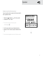
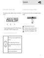
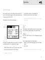
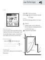
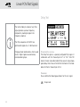
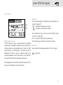
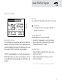
OPERATING MANUAL DIGIRATOR DR2 NTi Audio Contact Details Head Office NTi Audio AG Im alten Riet 102 9494 Schaan Liechtenstein, Europe Americas NTI Americas PO Box 131027 Tigard, Oregon 97281 USA China NTI China Room 722, 7F, Building 6-3A, No 1388, Bin He Rd. 215000 Suzhou, China Japan NTI Japan Ryogokusakamoto Bld. 1-8-4 Ryogoku, 130-0026 Sumida-Ku Tokyo, Japan Tel.: +423 239 6060 Fax: +423 239 6089 E-Mail: [email protected] Web: www.nti-audio.com Tel.: +1 503 684 7050 Fax: +1 503 684 7051 E-Mail: [email protected] Web: www.ntiam.com Tel.: +86 512 6802 0075 Fax: +86 512 6802 0097 E-Mail: [email protected] Web: www.nti-audio.com/cn Tel.: +81 3 3634 6110 Fax: +81 3 3634 6160 E-Mail: [email protected] Web: www.nti-audio.com/jp NTi Audio is an ISO 9001:2008 certified company. © All rights reserved. All information subject to change without notice Version 1.12 / Dec 2011 / Software 1.12 ® Minirator is a registered trademark of NTi Audio. ™ EXEL, XL2, Digilyzer, Digirator and MiniLINK are trademarks of NTi Audio. Table of contents Table of contents 1. Digirator Basics................................................................4 Introduction.....................................................................4 Notes..............................................................................5 Items included in the package........................................6 Accessories....................................................................6 2. Overview of the Instrument...........................................7 Connections....................................................................7 Buttons and operating elements.....................................8 The screen display..........................................................9 The main menu...............................................................9 Power supply................................................................ 11 Characteristics of the outputs ..................................... 12 Characteristics of the SYNC input................................. 13 3. Getting Started..............................................................14 Inserting the batteries................................................... 14 Fitting the protective shock jacket................................ 15 Attaching the hand strap............................................... 16 Connecting the Digirator............................................... 17 4. Operation....................................................................... 18 Switching Digirator on and off....................................... 18 Navigation in the menu bar . ........................................ 18 Selecting a test signal................................................... 19 Setting the parameters.................................................20 Setting the sampling frequency....................................22 Setting the Channel Status...........................................23 Configuring the output channels...................................23 System settings............................................................25 Configurations...............................................................26 5. Linear PCM Test Signals................................................28 Signal generation..........................................................28 Sine...............................................................................29 Sweep...........................................................................29 Chirp.............................................................................31 Delay Test......................................................................32 Pink Noise.....................................................................33 White Noise..................................................................34 Polarity..........................................................................34 Wave File Player............................................................35 6. Dolby / DTS Signals......................................................38 Signal generation..........................................................38 Test signals and formats...............................................40 7. Measuring Functions DR2.............................................43 Channel transparency testing.......................................43 I/O Delay test (Latency)................................................46 8. Updating the Instrument..............................................48 Firmware update...........................................................48 9. Tips and Trouble Shooting.............................................49 Faults and their correction............................................49 Resetting to the factory settings..................................51 Reloading wav-files.......................................................51 10. Technical Data...............................................................52 11. Further Information......................................................53 Registration...................................................................53 Warranty conditions......................................................54 Declaration of Conformity.............................................55 Information regarding disposal / recycling....................55 3 Basics 1. Digirator Basics Introduction Thank you for purchasing the Digirator. The Digirator DR2 is a reference grade digital audio generator with AES3, S/PDIF and ADAT outputs. As an extension to the common stereo audio test signals, DR2 also supports surround sound sequences for setup and testing of professional Dolby Digital, Dolby E, ProLogic II and DTS installations. The ultra stable internal clock generator can be synchronized to AES3, DARS, Word Clock as well as video signals. It further supports the measurements of channel transparency and I/O delay (latency) as well as clock frequencies. 4 Basics Notes Damage to equipment connected Damage from moisture The Digirator is a test generator and thus allows creating exceptional signals that do not appear in normal audio operations. Do not use the instrument in damp environments! Such generated signals may damage or destroy systems and loudspeakers if not operated carefully. The instrument can be permanently damaged by penetration of water, moisture or any fluid. Damage caused by opening the instrument Danger of electric shock Never open the instrument. Never connect the instrument to a power output! The instrument can be damaged if the housing is opened and your warranty will be invalidated. Non-compliance could result in injury to persons and/or damage to property that is not covered by the warranty guarantee. 5 Basics Items included in the package Accessories • Digirator DR2 • Protective shock jacket • Test signal backup DVD • Operating manual • XLR - BNC adapter (Neutrik NA2MBNC) • RCA - BNC adapter • USB cable • Hand strap • Pouch • System Case • Mains Power Adapter • Calibration Certificate 6 NTi Audio # 600 000 302 NTi Audio # 600 000 020 NTi Audio # 600 000 333 NTi Audio # 600 000 018 You can find further additional information on the website www.nti-audio.com Overview 2. Overview of the Instrument Connections The Digirator provides the following connections: 1 2 3 1 2 3 4 5 6 4 5 6 S/PDIF and AES3-id output 75 Ω AES/EBU output 110 Ω Optical output DC power socket SYNC input (AES3, Word Clock, Video) USB connection 7 Overview Buttons and operating elements 1 2 3 esc 9 level 8 2 3 8 esc wave Selection of the test signal. 5 freq Setting the output frequency. Also directly jumps to the „PARAM“ menu with the „SWEEP“ and „CHIRP“ test signals; and to file selection with „FILE”, „DOLBY” and „DTS”. 6 mute When pressed, it illuminates to indicate you have switched off (Muted) the output signal. The button also lights up during the cycle pauses of the „PNOISE” and „CHIRP” signal waveforms. 7 On / Off Switches the instrument Power off if held down for one second. Also switches the back-lighting on and off with a shorter press. 8 sens Changes the sensitivity of the frequency and level settings. 9 level Setting the output level. You can set the output signal unit to dBF or %. wave freq sens 1 4 4 5 mute 7 6 Terminates an entry and jumps to the top menu level. Rotary wheel Slow rotation: Precise setting of the value. Fast rotation: Setting the value in larger steps. Enter Confirming a selection. The following signals have a fixed output level: DTS, DOLBY, TRANSPAR, I/O DELAY. Overview The screen display The main menu 1 2 Menu bar 1 2 3 4 3 1 Menu bar Battery symbol: If the battery symbol lights up the batteries are almost completely discharged and must be replaced. 3 Carrier signal interface settings 4 Audio signal generation settings. 1 Function selection 2 Save and Recall instrument configurations 3 Select and configure output channels (individual mute or invert) 2 9 Overview Settings for signal generation 1 Settings for interface carrier signal 2 3 1 2 4 3 7 6 5 1 2 3 4 5 6 7 10 Test signal Start / Stop for certain test signals Parameters setup Single / continous mode for certain test signals Output frequency Units for the output level Output level 1 Settings and display of sampling frequency and clock source 2 Configuration and status display of the optical output 3 Channel status settings Overview Power supply Battery operation In order to be always able to use the Digirator flexibly, we recommend the use of batteries. We recommend you use only the NTi Audio DC supply. But if you want to make use of a different DC power supply unit, you must observe the following: Only use 3x AA, LR6 batteries. The battery consumption increases at higher levels and is based on the connected load. During operation, the battery temperature may increase noticeably. This is not a defect. The instrument can also be used with rechargeable batteries. Operation using mains power supply You can also connect the Digirator to mains power with a DC power supply unit. To do this, you will need the corresponding DC power supply accessory unit, which you can order from NTi Audio. Use an electrically-isolated, non-earthed linear DC power supply unit with 2.1 x 5.5 x 9.5 mm plug and connection . Only use DC power supply units with a voltage from 5 to 8 volts and a current of at least 500 mA. Do not use a switching power supply. Unbalanced connections in combination with a switching power supply can lead to noise interference and an unpleasantly high interference level when plugging in and out. Damage caused by using an inappropriate external DC supply is not covered by warranty. 11 Overview 2 SYNC IN XLR - 110 Ω, 75 Ω, High-Z 1 75 110 AES3, DARS 3 Clock Processing Characteristics of the outputs fs Word Clock, Blackburst Electrical Outputs (AES3, S/PDIF) Video 75 The Digirator features two electrical outputs that are equipped with a shared high quality transformer. Both outputs are earthfree and resistant to externally applied Phantom Power. Do not use both outputs in parallel. Digital Audio Transmitter 2 1 3 AES / EBU XLR - 110 Ω AES3-id S/PDIF RCA - 75 Ω Pin assignments of the XLR Output: 3 2 1 WAVE 1 2 3 DEFAULT The outputs feature interface carrier levels with fixed levels: AES3 : 6.0 Vpp (open) 3.0 ±0.2 Vpp (into 110 Ω) S/PDIF, AES3-id: 2.0 Vpp (open) 1.0 ±0.2 Vpp (into 75 Ω) FOLDER2 12 • Signal1.wav • Signal1.wav • Signal2.wav • Signal2.wav ... PIN 1 PIN 2 PIN 3 The concurrent use of both electrical outputs leads to reduced interface carrier levels that can lead to malfunction. AES3id For generating an AES3id compatible signal please use the supplied RCA to BNC adapter. The output signals meet the AES3-id standard and work well for S/PDIF signals. Optical output The optical output may be used concurrently with one of the electrical outputs. It can be configured either for „2 Channel“ or for „ADAT“ format. Overview Characteristics of the SYNC input The sampling frequency of the Digirator can be synchronized and locked to external devices. In order to do this, the sync signal is connected to the universal sync input circuitry via a female XLR connector to the DR2. An adaptor for connecting a BNC cable to the XLR input is also included as a standard accessory item with the DR2. Supported sync / clock formats The Digirator recognizes clock sources automatically as they are connected. There is no need for a manual selection of the sync format. The following formats are supported: • AES3 / DARS • Word Clock • Black Burst 20 kHz to 216 kHz (continuous) 32 kHz (+/- 100 ppm) 44.1, 48 kHz (x1, x2 , x4) (+/- 100 ppm) PAL (25 Hz) and NTSC (29.97 Hz) fs = 48 kHz 2 SYNC IN XLR - 110 Ω, 75 Ω, High-Z 1 75 110 3 75 Jitter suppression The extracted sampling frequency is fed into a clock recovery stage with high jitter attenuation. This ensures stable and optimized signals at the DR2 output. With input sampling frequencies that deviate more than 100 ppm from the AES standard sampling frequencies, no clock recovery will be executed. Under special circumstances this might lead to suboptimal stability of the output signal . DARS (Digital Audio Reference Signal) AES3, DARS Clock Processing Input impedance AES3 as well as Word Clock signals are separated by an electrically isolated transformer terminated with the nominal impedances of 110 ohm or 75 ohm. But Hi-Z mode is also supported, allowing trial operation of the DR2 in parallel with other devices. fs ... is an AES3 Signal, intended for synchronizing equipment. Its channel status data are marked accordingly by setting the DARS Bits. Word Clock, Blackburst Video 13 Getting Started 3. Getting Started Inserting the batteries Only use AA, LR6 batteries. You will need 3 AA batteries. The batteries may significantly warm up during operation. This is not a malfunction. The Digirator can also be operated with rechargeable batteries. For best battery performance only use new batteries of the same type and manufacturer. 1. Open the battery cover. 2. Insert three AA, LR6 batteries with the same state of charge, paying attention to the +/- marking in the battery compartment. 3. Close the battery cover once the batteries have been inserted. 14 2. 1. Getting Started Fitting the protective shock jacket The shock jacket protects the instrument against light impacts without impairing it’s easy operation. It is recommended to leave it mounted. 1. Push the lower end of your Digirator into the lower end of the protective shock jacket. 2. Push the upper end of the Digirator into the protective housing. Damage through impacts / shocks 1. 2. The protective shock jacket shields your Digirator against reasonable impacts that could occur in normal use. You must further protect the instrument from extreme stress, exposure to liquids, and from extremes of heat or cold. Please do not drop the instrument! Damage caused by dropping or impact is not covered by warranty. 15 Getting Started Attaching the hand strap To prevent you from accidentally dropping the DR2, a hand strap is supplied with the instrument. You can also fit the hand strap when the protective shock jacket of the DR2 has been fitted. 1. 1. Pull the hand strap through the opening. 2. Pull the rear part of the hand strap through the loop of the front part. 3. Pull the hand strap tight. 2. 3. 16 Getting Started Connecting the Digirator XLR-connection Connect the Digirator to your digital audio device using an XLR cable. Note that the locking pin of the XLR connector will then be located on the lower side of the instrument! RCA connection Connect the Digirator to the digital input of the unit to be tested using a good quality RCA cable. Please note that not all RCA cables are suitable for digital audio use. Optical connection Connect the Digirator to the optical input of the unit to be tested using an optical TOSLINK cable. The cover flap of the output opens automatically with the insertion of the cable. 1. 2. 17 Operation 4. Operation Navigation in the menu bar Switching Digirator on and off The menu bar is divided into three parts. On the left-hand side, you can choose between the Generator, Transparency-Test, I/O Delay (Latency) and System functions. Switching the Digirator on To switch the Digirator on, press the “On/Off” button. The display lighting is switched on. Switching the Digirator off To switch the Digirator off, press the “On/Off” button and hold it down for one second. 1. To do this, select the left side of the menu bar with the rotary wheel and confirm with “Enter”. A selection window opens. 2. Select the desired function with the rotary wheel. 3. Confirm the selection with “Enter”. You have now selected the desired function. In the middle section of the menu bar you may mute or invert individual channels of the output signal. In the right-most menu you can save and recall configurations (see “Configurations”). 18 Operation Selecting a test signal You have two choices for selecting test signals. You can use either the direct access buttons or the rotary wheel. Signal selection using the direct access buttons 1. Ensure that GENERATOR 1 is selected in the menu bar. 2. Press the “wave” button. Signal selection using the rotary wheel 1. Ensure that GENERATOR 1 is selected in the menu bar. 2. Select “WAV” 2 with the rotary wheel. 3. Press “Enter”. A selection menu appears. A selection menu appears. 1 2 3. Select the desired test signal with the rotary wheel. 4. Press “Enter”. You have now selected the test signal. 4. Select the desired test signal with the rotary wheel. 5. Press “Enter”. You have now selected the test signal. 19 Operation Setting the parameters You have two possibilities for setting up the parameters of the test signals. Use either the direct buttons or the rotary wheel. Setting parameters using the rotary wheel 1. Turn the rotary wheel. The selected parameters will be marked with a black bar. Setting parameters using the direct access buttons 1. Press the “level” or “freq” button. You have selected the desired parameter. 2. Turn the rotary wheel to set the parameter. 3. Confirm the setting with the “Enter” button. You have now set up the parameter. 2. Confirm your choice with the “Enter” button. The parameter display blinks. 3. Turn the rotary wheel to set the parameter. 4. Confirm the setting with the “Enter” button. You have now set the parameter. 20 Operation Setting the sensitivity of the rotary wheel You can set up the sensitivity (step size) of the rotary wheel. To do this, proceed as follows: 1. Select Level or Frequency 2. Hold down the “sens” button. with the rotary wheel. The current sensitivity of the rotary wheel will be displayed 1 . 3. Turn the rotary wheel to set up the desired sensitivity. 4. Release the “Sens” button to accept the desired sensitivity. 1 You have now changed the sensitivity of the rotary wheel. 21 Operation Setting the sampling frequency Internal clock source You may choose to have the Digirator DR2 either generate the sampling clock internally or be synchronized to an external clock source (see „Synchronizing to an external clock“). With no signal applied to the SNYC input you may choose among the internally generated clock frequencies: 1. Select from the available internal values with the rotary wheel and then press „Enter“ The actual sampling frequency value is highlighted with a blinking bar. 2. Turn the wheel to alter the sampling frequency. 3. Confirm your selection by pressing „Enter“. You have changed the sampling frequency. Synchronization to an external clock The SYNC input of the DR2 is continuously monitored and scanned for useable clock references (see „ Characteristics of the SYNC input“). In this mode the SYNC input is terminated with Hi-Z. As soon as a clock signal is detected a window for selecting the termination impedance appears: Note also that there are different ways to route the independent reference clock to the two devices. If the reference clock source has multiple buffered outputs, separate cables may be connected to the SYNC input of the DR2, and to that of the device under test, in a “star” configuration. But if a single reference clock output must drive both the DR2 and the device under test, the first connected sync input would be placed in high impedance (Hi-Z) mode, and the second (or last) would be terminated. 1. Choose the desired impedance with the rotary wheel and press „Enter“ to confirm. The following termination impedances are available: For non-linear PCM Signals (Dolby / DTS) as well as in the TRANSPAR mode the sampling frequency is fixed to 48 kHz. 22 Video Word Clock AES3 / DARS 75 Ω • • • 110 Ω • Hi-Z • • • Operation Setting the Channel Status Configuring the output channels You can define the most important settings in the channel status data: The output channels of the DR2 can be individually muted or inverted. 1 2 3 1. Choose the desired parameter 1 , 2 or 3 with the rotary wheel and press “ENTER“ to change the value. You have changed the Channel Status data. Both output channels are active Channel A is active, channel B is muted Channel A is muted, channel B is active Channel B is has inverted polarity (-180°) The settings are always applicable for both channels. All non-visible settings of the channel status information are automatically set by the DR2. Emphasis settings 3 do not have any influence on the signal generation. 23 Operation Optical output There are three operation modes available for the optical output: The optical output can operate up to the following maximum sampling frequencies: 2 channel mode (AES) ADAT mode (8 channels) Channels 1, 3, 5, 7 are fed from channel A of the stereo signal , while channels 2, 4, 6, 8 contain the audio of channel B Optical output is switched off You may alter settings as follows: 1. Select the value under the LED icon with the rotary wheel: 2. Press “ENTER“ to change the value. You have configured the optical output 24 2 channel mode: 106 kHz ADAT: 55 kHz At any selected sampling frequency higher than the given limits the optical output is automatically disabled and the visual icon indicators behind the symbol will not be present: Operation System settings You can adjust various system settings of your instrument. To do this, switch to System 1 in the menu bar using the rotary wheel and confirm with “Enter”. The possible system settings are displayed: 3. Turn the rotary wheel to set the desired time. 4. Confirm the entry with the “Enter” button. You have now changed the switch-on time of the PowerSave mode. Backlight 1 2 3 4 5 Power Save The Power Save mode switches the instrument off if no button has been pressed within an adjustable time period. 1. Select the Power Save function 2 using the rotary wheel. 2. Confirm the selection with the “Enter” button. AUTO: The backlight will be switched on automatically during operation, and will be switched off again after a period of time. MANUAL: Press the “On/Off” button to switch the background lighting on and off. You can choose between “Auto” and “Manual”. 1. To do this, select the Backlight 3 function with the rotary wheel. 2. Press “Enter”. The display now changes between “Auto” and “Manual”. The display starts to blink. 25 Operation Configurations Firmware Displays the version number, with the possibility to carry out a firmware update for the DR2 4 (see “Updating the Instrument”). With the DR2, you can store your current instrument settings as configurations, and recall these at a later date. Storing configurations 10 configuration storage locations are available to you. Display of the serial number You can read out the instrument’s serial number bottom line. 5 from the Setting the contrast 1. Using the rotary wheel, select CONFIG in the menu bar. 2. Confirm with “Enter”. The following menu is opened: Changing the contrast of the screen display. To do this, proceed as follows: 3. Select STORE and confirm with “Enter”. 1. Hold down the “esc” button and turn the rotary wheel until the desired contrast is obtained. You have now changed the contrast of the screen display. 26 The following selection menu is opened: Operation 4. Select a memory location with the rotary wheel and store your configuration by confirming the selection with “Enter”. You have now stored the current instrument settings as a configuration. following A removable memory drive will be indicated on the computer. 2. Select the CONFIG sub-folder. Calling up configurations 1. Use the rotary wheel to select CONFIG in the menu bar. 2. Confirm with “Enter”. The 1. Connect your DR2 to a computer via USB. menu is opened: You will see the stored configurations of your DR2. 3. Copy this data to your computer. 4. Connect another DR2 to the computer via USB. 5. Copy the previously copied data into the CONFIG sub-folder by overwriting the data therein. You have now transferred configurations from your DR2 to 3. Select RECALL and confirm with “Enter”. 4. Select the desired configuration in the Selection menu and confirm with “Enter”. You have now loaded the desired configuration. Transferring configurations to another device You have the possibility of transferring stored configurations to another device. another DR2. In order to easily remember configurations you may rename them. For altering the file names, connect the DR2 to a computer via USB and rename the files in the CONFIG folder. Only the first 10 configurations are shown in the display. 27 Linear PCM Test Signals 5. Linear PCM Test Signals Signal generation The Digirator DR2 flexibly generates linear PCM test signals such as sine, noise or even other arbitrary signals from 48 kHz wave (WAV) files. The match and lock of the selected sampling rate to the applied reference signal is handled by an internal sample rate converter. This configuration ensures that the generated audio signal frequency is not dependent on the sampling rate but left unchanged. The sample rate converter, featuring a high dynamic range of 144 dBA, does not affect the audio signal quality specification. Audio frequency range The generated audio signals feature a bandwidth of 24 kHz, sine signals can be synthesized up to 20 kHz. Settings violating the Nyquist theorem are not prohibited as the sample rate converter will simply attenuate these signals. (e.g. Sine signal with f = 20 kHz at a sampling rate of 32 kHz is attenuated because sampling rate should be at least twice the signal frequency). DR2 internal signal flow for linear PCM test signals Digital Audio Receiver Analyzer Sample Rate Converter Signal Generator Digital Audio Transmitter fs = 48 kHz INT fs = 20 - 216 kHz EXT Audio signal Clock signal not active 32.0 kHz 44.1 kHz (*2 , *4) 48.0 kHz (*2 , *4) Video (PAL, NTSC) Word Clock AES3, DARS Digital Audio Receiver Analyzer Sample Rate Converter 28 Signal Generator Digital Audio Transmitter Linear PCM Test Signals Sine Sweep Characteristics and use Pure sinusoidal signals are required for many standard audio measurements. The Digirator provides a wide and adjustable output level range and selectable output frequencies. Characteristics and use Stepped sweep signals with a resolution of up to 1/12 octave can be generated over a freely-selectable frequency range. An audio analyzer like the Minilyzer or Digilyzer from NTi Audio can automatically trigger to this signal sequence to measure the frequency response. Parameter You can define the following parameter for this test signal: Output frequency Output level Starting the Sweep signal 1. Select the “START” symbol with the rotary wheel. You can interrupt a running sweep via the “STOP“ symbol. 29 Linear PCM Test Signals Sweep Signal modes Using the “MODE” symbol, you can run the test signal in the following modes: f f STOP B Once-only : Plays the test signal once Continuous : Repeats the test signal Parameter You can define the following parameter for this test signal: Output level The frequency display is for information only. The current frequencies will be displayed here once the SWEEP test signal has been started. You can configure the signal sequence here. A 1 kHz t STEP t TRIG f START t A The sweep recording starts as soon as the frequency drops from 1 kHz to fSTART. B 30 f RES The end of the sweep is signaled by a falling frequency. Linear PCM Test Signals Chirp Once-only : Plays the test signal once. Continuous : Repeats the test signal after an adjustable pause (t ). PAUSE Parameter You can define the following parameters for this test signal: Characteristics and use A Chirp is the name for a signal whose frequency continually changes over time (also known as continuous sweep). It is used for the recording of frequency responses, the measurement of impulse responses and the acoustic assessment of rooms. Starting the Chirp signal 1. Select the START symbol with the rotary wheel. If this is activated, it turns into a STOP symbol Output level The frequency display is purely for information only. The current frequencies will be displayed here after the start of the CHIRP test signal. Configuration of the signal sequence. f t CHIRP f STOP t SCALE = LIN , which t PAUSE will end the test signal when selected. Chirp Signal modes Using the “MODE” symbol, you can run the test signal in the following modes: t SCALE = LOG f START t 31 Linear PCM Test Signals Delay Test The normal fading in and out of any Chirp signal generates spurious frequency components, leading to ripple in the frequency response. The Chirp sequences of the DR2 are optimized for ripple of ± 0.2 dB maximum. Chirp parameter combinations which would result in higher ripple are automatically corrected during input. Characteristics and use The Delay Test signal is a specially configured Chirp signal. In combination with the “Acoustilyzer AL1“ or “XL2“ from NTi Audio, it makes it possible to determine acoustic signal propagation delay times. You can find further information in the handbooks for the AL1 Acoustilyzer or XL2. Parameter You can define the following parameters for this test signal: Output level 32 Linear PCM Test Signals Pink Noise 1 2 Characteristics and use The Pink Noise test signal is characterized by flat amplitude response per octave band of frequency (or per any other constant percentage unit of bandwidth) up to its band limit; high spectral density, an infinite period (> 100 years) and 20 kHz bandwidth. Pink Noise is used as a reference signal for the setup of loudspeaker systems (PA systems), with a Real Time Analyzer (RTA) executing the required measurements. Operation You can choose between the following test signal modes with the MOD setting 1 : CONT : generates a continuous test signal. : generates a intermittent test signal. You can determine the cycle times of the intermittent signal with the CYC setting 2 . (3/3 = 3 seconds of signal and 3 seconds pause.) These settings have no effect in the continuous mode. Parameter You can define the following parameters for this test signal: Output level When operated in the intermittent mode, Pink Noise also forms the basis for reverberation time measurements. 33 Linear PCM Test Signals White Noise Polarity Characteristics and use The White Noise test signal has a high spectral density, Gaussian amplitude distribution and a nearly infinite period (> 100 years). White Noise is used for all measurements with FFT analyzers or where a linear frequency scale is used, and has a constant signal power per Hertz and a 20 kHz bandwidth. Characteristics and use The saw-tooth test signal is ideally suited for checking the polarity of loudspeakers. The “Minilyzer ML1”, “Acoustilyzer AL1” and “XL2“instruments from NTi Audio detect this signal and use it to indicate polarity. Parameter You can define the following parameters for this test signal: Output level 34 Parameter You can define the following parameters for this test signal: Output level The frequency display is for information only. The frequency cannot be adjusted. Linear PCM Test Signals Wave File Player Parameter You can define the following parameter for this test signal: 1 2 Characteristics and use With the Digirator, you can play back your own test signals and sequences from wave (WAV) files. The test sequences will be seamlessly looped without pauses. For a better overview, wave files storage in the DR2 is organized using sub-folders. The DR2 is already equipped with a series of demo sequences in the WAV file format. You can create a link to a computer at any time via the USB interface and can exchange existing WAV files or add new ones. Output level The output level of this test signal is adjusted in dBF (dB full scale) or %. Possible applications Possible applications include, for example: • channel ID / line occupation „in-use“ transmissions • Musical signals for the assessment of PA systems • Playing back complex test signals Selecting a folder 1. Select the folder symbol 1 with the rotary wheel. 2. Confirm with “Enter”. 3. Select the desired folder with the rotary wheel. 4. Confirm with “Enter”. You have now changed the current playback folder. 35 Linear PCM Test Signals Selecting a wav-file 1. Use the rotary wheel to select the file symbol 2 . 2. Confirm with “Enter”. 3. Select the desired wav-file with the rotary wheel. 4. Confirm with “Enter”. The wav-file will be played. Loading your own wav-files Wave files for the DR2 must conform to the following requirements: • 48 kHz sampling frequency • Mono or Stereo • 16 - 24 bit definition If a wave file does not meet the requirements, the playback stops and the “mute” button lights up continuously red. 36 To load WAV-files, you will need a computer with the following minimum specifications: • PC with Windows 98SE • Macintosh computer with OSX • Available USB port 1. Connect the DR2 to the computer via USB. The DR2 appears on your computer as a removable data storage medium. 2. Open the “WAVE” sub-folder on the removable medium All the sub-folders in the “Wave” folder now appear in the folder selection 1 . You may add additional sub-folders to this folder level as required. Linear PCM Test Signals 4. Copy the desired files into the folder. WAVE You have now loaded your Wave files. FOLDER1 FOLDER2 • Signal1.wav • Signal1.wav • Signal2.wav • Signal2.wav • ... • ... ... Copyright NTi Audio delivers a set of demonstration wave files with the DR2. These wave files are licensed to you only for playback with an NTi Audio unit. Any further usage is forbidden. 3. Open one of the sub-folders in the “WAVE” folder. If necessary, you can make use of the other standard possibilities of a removable data medium. For example, you can copy WAV files from the DR2 onto your computer or delete unnecessary files. 37 Dolby / DTS Signals Signal Generator Digital Audio Transmitter fs = 48 kHz INT 6. Dolby / DTS Signals fs = 20 - 216 kHz EXT Signal generation 32.0 kHz 44.1 kHz (*2 , *4) 48.0 kHz (*2 , *4) Video (PAL, NTSC) Word Clock AES3, DARS DR2 internal signal flow for Dolby / DTS test signals Dolby and DTS signals are compressed, multi-channel audio signals. They are transmitted as non-linear PCM signals and need to be processed by a Dolby / DTAS decoder before they can be used as multi-channel audio. The available test signals have been externally encoded and are implemented as WAV files. All DOLBY and DTS signals stored in the DR2 have been encoded and recorded on DOLBY and DTS certified equipment. Digital Audio Receiver Analyzer Sample Rate Converter Signal Generator Digital Audio Transmitter fs = 48 kHz INT The sampling frequency is fixed to 48 kHz and may by synchronized to an external reference of 48 kHz within ±100 ppm accuracy. The wave files are stored in the sub directories DOLBY and DTS. All files stored in these folders are treated as „Non-Linear PCM“ signals and the channel status is automatically marked accordingly. 38 fs ≈ 48 kHz EXT Audio signal Clock signal not active 32.0 kHz 44.1 kHz (*2 , *4) 48.0 kHz (*2 , *4) Video (PAL, NTSC) Word Clock AES3, DARS Dolby / DTS Signals The handling of Dolby and DTS files is identical to wave files, described in the previous chapter. 1 Select the signal 1. Select the file symbol 2 with the rotary wheel. 2. Confirm with Enter. 3. Select the desired signal with the rotary wheel. 4. Confirm with Enter. The selected test signal is immediately played back. 2 Sequence of test signals The order sequence of the files is sorted first by file extension (e.g. file.001) and secondarily by actual file name. This enables maximum flexibility in grouping similar test signals together. The test signals in the directories are sorted by non-linear format type. Select the multi-channel format 1. Select the desired signal format (DLBY or DTS) 2. Use the rotary wheel to select the group symbol 3. Confirm with Enter. 4. Select the desired format. 5. Confirm with Enter. 1 . You have changed the multi-channel format. 39 Dolby / DTS Signals Test signals and formats Test signals Name CH_ID_L CH_ID_C CH_ID_R CH_ID_LS CH_ID_RS CH_I_LFE PNOISE PNOI_LFE POLARITY SINE_80 SINE_400 SINE_997 SINE_1K SINE_10K VOICE 40 Test signal On each of these channel ID files: There is the spoken channel identification followed by a 400 Hz sine signal. Spoken channel identification with pulsed 80 Hz sine signal on LFE channel. Pink Noise, -20 dBFS, L, C, R, LS, RS: 20 - 20‘000 Hz, LFE: 20 - 120 Hz Pink Noise, -20 dBFS, 20 - 120 Hz Polarity test signal Sine 80 Hz, 0 dBFS, on all channels Sine 400 Hz, 0 dBFS, on all channels Sine 997 Hz, 0 dBFS, on all channels Sine 1.000 Hz, 0 dBFS, on all channels Sine 10.000 Hz, 0 dBFS, on all channels Reference voice announcement on all channels, -20 dBFS Length 0:25 0:25 0:25 0:25 0:25 0:25 0:30 0:15 0:15 0:15 0:15 0:15 0:15 0:15 0:21 Dolby / DTS Signals Formats Copyright Name D_20 D_51 Format Dolby Digital 2.0 @ 256 kbit/s Dolby Digital 5.1 @ 448 kbit/s E16_51 E20_51 E20_5120 Dolby E 5.1 @ 16 Bit Dolby E 5.1 @ 20 Bit Dolby E 5.1 + 2.0 @ 20 Bit All Dolby and DTS signals stored in the DR2 are licensed to you, and must only be used and played back on the DR2. Any further use of these files is strictly forbidden. PROLOG2 Dolby ProLogic IIx @ PCM Lt/Rt (5:2:5) Test Signals 755K_20 755K_51 1509K_51 DTS 2.0 @ 754.5 kbit/s DTS 5.1 @ 754.5 kbit/s DTS 5.1 @ 1509 kbit/s Due to the huge size of the non-linear PCM signals, not all files will fit into the internal flash disc of the DR2 at the same time. The test signal backup DVD includes all available non-linear PCM signals. 41 Dolby / DTS Signals Dolby ProLogic II The Dolby ProLogic II format is an uncompressed linear PCM format that codes the channel assignment in the L/R phase relation. You will therefore find the ProLogic II files in the WAVE folders, not in the Dolby folder. Levels All announced levels of the non-linear signals refer to audio levels prior its coding into the non-linear format. Minor level differences may occur due to the encoding process. 42 Measuring Functions 7. Measuring Functions DR2 Channel transparency testing The displayed validity bit 2 and channel status details 3 are for information only. They are not part of the transparency measurement. The channel transparency test verifies whether the audio and auxiliary data of a digital transmission channel are transparently transmitted. The transparent transmission is crucial for nonlinear PCM formats such as surround sound. The verification always covers both audio channels. 1 3 2 Function The test signal used in the DR2 is a short deterministic noise sequence. The signal stream applied to the SYNC input is monitored and verified for a 16, 20 or 24 bit correlation. AES3 transmission format frames Preamble 1 2 3 Result of the analysis Status of the validity bit of the input signal Channels status information of the input signal 0 3 Auxiliary LSB 4 8 7 Audio Data 11 12 MSB V U C 27 28 29 30 31 P <--------- 16 Bit ----------> <----------------- 20 Bit ----------------> <------------------------ 24 Bit ------------------------> 43 Measuring Functions A nontransparent signal is indicated by the “DATA CHANGED” message. This means that the received bit pattern is different to the expected bit pattern. This could be caused by any changes in e.g. the gain setting or in the word length with added dither. Sampling frequency, synchronization and clock source The sampling frequency is fixed to 48 kHz but can be synchronized to an external reference with 48 kHz within ±100 ppm range. External-synchronization is very helpful for offline tests. e.g. to record the transparency test signal on a recording system and analyze as played back. Also the test may also optionally be conducted using two DR2 units in different locations, with one acting as the signal source and the other as the analyzer. With a word clock or video signal applied to the DR2, it automatically tries to synchronize after querying for the termination impedance choice. With a valid AES signal applied the user should determine whether the DR2 should Sync (slave mode) or continue to run from the internal clock (Master mode). 44 INTERNAL Synchronization In this mode the DR2 acts as a clock master and the connected device or system is synchronizing its clock to the DR2. Select this mode if the device under test is unable to generate its own clock, or if the device under test automatically synchronizes to signals presented to its input. SYNC INPUT (external synchronization) In this mode the device under test is the clock master and the DR2 synchronizes to this connected device by selecting clock via “SYNC INPUT“. Synchronization is necessary to prevent from losing samples through drop-outs or glitches. With no valid clock applied to the SYNC input of the DR2, the internal sampling frequency starts to drift and the external synchronization aborts. With no Sync signal the DR2 switches back to its internal clock generation and transmits the test signal derived from its internal clock. As soon as this transmitted signal again reaches the SYNC input, the selector boxes for IMPEDANCE and CLOCK source will appear again. fs = 48 kHz INT fs = 20 - 216 kHz EXT 32.0 kHz 44.1 kHz (*2 , *4) 48.0 kHz (*2 , *4) Digital Audio Transmitter Test procedure For testing the transparency of a transmission channel you profs = 48 kHz 32.0 kHz INT ceed as follows: 44.1 kHz (*2 , *4) fs ≈ 48 kHz INT fs ≈ 32 - 48 kHz EXT 32.0 kHz 44.1 kHz (*2 , *4) 48.0 kHz (*2 , *4) Video (PAL, NTSC) Word Clock AES3, DARS Signal flow during transparency test An intermittent appearance of INPUT IMPEDANCE and CLOCK SOURCE is a Digital Audio strong indicator that the device orReceiver system under test does not create its own clock, but regenerates the input clock. To solve Sample Rate Converter this loop-back problem switch back to CLOCK SOURCE INTERNAL. Signal Generator fs = 48 kHz Video (PAL, NTSC) Word Clock AES3, DARS Important Analyzer Measuring Functions Sample Rate Converter Signal Generator The result of the continuously measured transparency anal- Digital Audio Transmitter fs = 48 kHz INT 48.0 kHz (*2 , *4) 1. Connect the output of the DR2 to the Video input of the system (PAL, NTSC) EXT Word Clock under test. AES3, DARS 2. Connect the output of the system under test with the SYNC input of the DR2. 3. Select the settings for clock source and termination. Digital Audio Receiver Analyzer fs = ~ 48 kHz EXT 32.0 kHz 44.1 kHz (*2 , *4) 48.0 kHz (*2 , *4) Video (PAL, NTSC) Word Clock AES3, DARS Audio signal clock signal not active ysis is displayed. 45 Measuring Functions I/O Delay test (Latency) The function I/O Delay (latency) test determines the exact time delay which a piece of equipment or an entire system is introducing. For this test, the SYNC input connector of the DR2 is used for receiving the delayed signal. 3 1 2 Function DR2 generates a short test burst every 2 seconds. The SYNC input is continuously monitored and the delay calculated. Level adjustments and minor distortion do not affect the measurement result. Sampling frequency, synchronization and clock source The sampling frequency can be selected to be either 32, 44.1 or 48 kHz. These frequencies can also be used for external synchronization, provided the accuracy is within ±100 ppm. 46 The sampling frequency of the input signal may be non-synchronized and range anywhere from 20 - 216 kHz. Right after the connection of a signal to the SYNC input, the DR2 queries for the desired termination impedance and after that whether the clock should be generated internally or synchronized to the external source. Also refer to the synchronization details outlined in the section „Channel transparency testing“. Test sequence For measuring the I/O delay (latency) of a device, please proceed as follows: 1. Connect the output of the DR2 with the input of the device under test. 2. Connect the AES3 output of the device with the SYNC input of the DR2. 3. Make the proper settings for termination impedance and clock source. The result of the I/O delay (latency) measurement is now continuously displayed. Measuring Functions PAL / NTSC settings The measured I/O delay time (latency) is displayed in milliseconds 1 as well as in video frames 2 . To alter between PAL and NTSC settings, proceed as follows: Digital Audio Analyzer Receiver DR2 internal signal flow for the I/O Delay measurement 1. Navigate the cursor with the rotary wheel to the field displaying NTSC or PAL 2 .Sample Rate Converter time and video frames. 2. Press „ENTER“ to alter between Signalconfigured the units for the FRAME Digital Audio You have display. Generator Transmitter Non-equal values for channel A and B fs = 48 kHz kHz In case there is a non-equal delay value for32.0channels A and B, INT 44.1 kHz (*2 , *4) the instrument will display the two different respective values 48.0 kHz (*2 , *4) fs = 20 - 216 kHz in an alternating sequence. The channel display 3 follows the Video (PAL, NTSC) EXT actual displayed channel. Word Clock fs = 20 - 216 kHz Analyzer Sample Rate Converter Signal Generator Digital Audio Transmitter fs = 48 kHz INT fs ≈ 32 - 48 kHz EXT AES3, DARS Digital Audio Receiver Analyzer Audio signal Clock signal not active Analyzer Sample Rate Converter Signal Generator Digital Audio Receiver 32.0 kHz 44.1 kHz (*2 , *4) 48.0 kHz (*2 , *4) Video (PAL, NTSC) Word Clock AES3, DARS Digital Audio Receiver Sample Rate Converter Digital Audio Transmitter Signal Generator Digital Audio Transmitter 47 Updating the Instrument 8. Updating the Instrument Firmware update You can find the firmware version of your instrument as follows: 1. Select “SYSTEM” in the menu bar. 2. Confirm the selection with the “Enter” button. The firmware version of the instrument is displayed. Kindly register your instrument at http://my.nti-audio.com (for details see chapter “Further Information”). Upon registration you may access the support page, which offers • detailed update instructions • firmware revision history Proceed as follows to update the firmware: 1. Select “SYSTEM” in the menu bar. 2. Click on Firmware and follow the instructions on the screen of the DR2. You have updated your DR2. 48 In order to update the firmware, you will need a computer with the following minimum specifications: • PC with Microsoft® Windows 2000 or later • an available USB port • Internet access Trouble Shooting 9. Tips and Trouble Shooting Faults and their correction Fault Fault finding Cause Remedy The DR2 does not generate an output signal. „mute“ button blinks. You have switched the instrument to Mute. Press the “mute” button. “mute” button lights up continuously. You have called up the “Pink Noise” (PNoise) test signal or you are in the Pause cycle of the Chirp test signal. Wait until the pause has ended. Cable not plugged in correctly or mis-wired. Plug in the cable correctly and check pin wiring. Screen contrast poor. Wave Files, DTS or Dolby Wave files are not played back. Contrast needs to be adjusted. “mute” button lights up continuously. Press the “Start” button. Press “esc” and operate the rotary switch to set the contrast. You have loaded a non-sup- Load a supported Wave ported Wave format. format (see page 36). 49 Trouble Shooting Fault INPUT IMPEDANCE and CLOCK SOURCE window appears intermittently. 50 Fault finding Cause Remedy You have selected SYNC INPUT Select clock source INTERNAL or but the device connected is disconnect the Sync cable. not acting as a clock master. Configure the external device to act as clock master. Trouble Shooting Resetting to the factory settings If the Digirator reacts unexpectedly, a reset to the factory settings might solve the problem. 1. Switch the instrument off. 2. Hold down the “esc” button and simultaneously operate the “On/Off” button. The confirmation of the reset is displayed on the screen. Reloading wav-files You can reload the Wave, Dolby and DTS files of the DR2 that were installed at the factory. The files are available on the Test signal backup DVD. 51 Technical Data 10. Technical Data Format Consumer/Professional, up to 24 bit audio Sampling Frequencies / Outputs XLR, RCA: 32, 44.1, 48, 88.2, 96, 176.4, 192 kHz Optical: up to 96 kHz ADAT: up to 48 kHz Accuracy: ± 2.5 ppm Outputs Inputs Linear PCM Signals Non-linear multichannel signals Wave File Format Frequency Settings 52 • AES3 (110 ohms) XLR • S/PDIF (75 ohms) RCA • AES3id (75 ohms) with RCA to BNC adapter • TOSLINK: Stereo and ADAT XLR Sync. input for: • AES3, DARS • Video (NTSC, PAL) • Word Clock using BNC to XLR adapter Sine, Polarity Test Signal, Delay Test Signal, Pink Noise (crest factor = 4.42), White Noise (crest factor = 3.47), Playback of Wave Files A comprehensive library of pre-encoded surround sound signals is available in the following formats: • Dolby Digital • DTS • Dolby E • Dolby ProLogic II Sampling frequency: Resolution: 48 kHz 16, 20, 24 Bit, Mono + Stereo Range: Step width: Accuracy: 10 Hz - 20 kHz min 1 digit steps 0.01% Stepped Sweep Function Frequency range: Step width: Sweep speed: selectable, 10 Hz - 20 kHz 1/1, 1/3, 1/6, 1/12 octave selectable, 0.5 - 5 s / step Gliding Sweep (Chirp) Function Frequency range: Increment: Chirp speed: selectable, 20 Hz - 20 kHz linear / logarithmic 1.0 - 39 seconds per sweep Level Units dBFS, % Output Level Range -100 dBFS to 0 dBFS Distortion THD+N of the synthesized sine signal: -138 dB (22 Hz - 22 kHz, AVG, @ 1 kHz, typical) USB Functionality • for firmware update • mass storage device Flash Memory • 512 MByte • for storing wave files and configurations Display Graphical, with back illumination Auto-Power-Off 10, 30, 60 minutes or OFF Batteries • 3 x AA Alkaline dry cells or rechargeable equivalents • Battery life typ. 10 hours (continuous) Temperature Range 0° to 45° C (32° to 113° F) Humidity < 90% rel. humidity, non-condensing Dimensions (LxWxH) 152 x 81 x 43 mm (incl. protective shock jacket) Weight 310 g (11 oz.) incl. batteries Further Information 11. Further Information Registration Register as a customer with My NTi Audio and benefit from the following possibilities: • Keep your products up-to-date Access free firmware and software updates. • Activate options Enable additional functions for your products. • Access premium content Access downloads, information and specific support for your products. • Receive application and product news Subscribe to the NTi Audio Newsletter. • Get fast worldwide support Register your products for fast support. • Confirm your ownership Allows us to contact you with important product notifications and provides a product record in case of loss or theft. How to Register • Open the web page “http://my.nti-audio.com”. • You are prompted to login or create the My NTi Audio Account. • The web page “My Products” opens. • Select the product type and enter the serial number. • Confirm with “Register”. • Now the product is listed in the table “My Products“. Congratulations, your NTi Audio product is registered. 53 Further Information Warranty conditions International warranty NTi Audio guarantees the function of the DR2 and their individual components for a period of one year from the date of sale. During this period, defective instruments will be repaired free of charge, or will be replaced. Limitations Opening the unit case voids the guarantee. These guarantee provisions also do not cover accessories; nor damage caused by accidents, immersion in or exposure to water or other fluid, transportation; incorrect use, or carelessness, nor the installation of any parts that were not delivered with the instrument, the loss of parts, connection to any AC mains voltage; nor operation with non-specified input voltages, adapter types or incorrectly inserted or leaking batteries. In particular, NTi Audio accepts no responsibility for incidental or consequential damages of any kind. The guarantee will be voided if repairs or service work are carried out by any third parties who are not part of an approved NTi Audio Service Center. 54 Repair of the Digirator DR2 In the case of faulty functioning or damage please contact your local NTi Audio partner for assistance. If your instrument needs to be returned for service, kindly follow the service guidelines at www.nti-audio.com/service. Calibration The Digirator DR2 has been carefully tested during production and performs to the specifications listed in the “Technical Data” chapter. NTi Audio recommends yearly calibrations of the instrument. For the calibration of your instrument kindly follow the service guidelines at www.nti-audio.com/service. Declaration of Conformity Information regarding disposal / recycling CE / FCC Compliance Statement We, the manufacturer NTi Audio AG Im alten Riet 102 9494 Schaan Liechtenstein, Europe hereby declare that the Digirator DR2 product, approved in 2007, complies with the following standards or other standard documents: EMC: 89/336, 92/31, 93/68 Harmonized standards: EN 61326-1 Dispose of the instrument in accordance with the legal environmental regulations in the country. Regulations for the European Union and other European countries with corresponding laws: The instrument must not be disposed of in the household garbage. At the end of its service life, bring the instrument to a collecting point for electrical recycling in accordance with the local legal regulations. This declaration will become invalid if modifications to the instrument are carried out without the written approval of NTi Audio. Other countries outside the European Union: Date: 01.12.2007 Signature: Contact the respective authorities for the valid environmental regulations in the country. Position: Technical Director E 500 dt 12.11