1
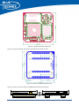
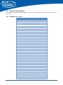
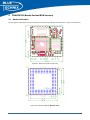
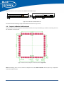
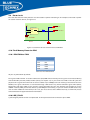
Figure 4-3 shows a side view of the Core Module with border pads.
Figure 4-3: Side View of the Border Pads
The total minimum mounting height of the Border Pad version is only 3.1mm!
4.2
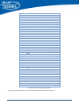
Footprint of Border Pad Baseboard
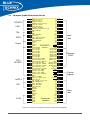
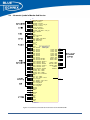
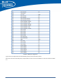
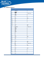
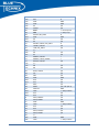
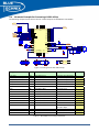
Figure 4-4 shows the pin assignment of the Border Pad Version. The pin Numbering is clockwise ascending. The Pins
No. 10 and 48 are not present.
Figure 4-4: Border Pad Footprint for the Base Board (top view)
Note: Conducting paths and vias within the footprint must be solder resistant. Do not place any component
within the footprint either.
TCM‐BF537 v1.x‐Hardware User Manual 21