1
US007532771B2
(12) Ulllted States Patent
(10) Patent N0.:
Taylor et al.
US 7,532,771 B2
(45) Date of Patent:
(54)
IMAGE PROCESSING SYSTEM FOR
DIGITAL COLLAGE
(75)
Inventorsl Stuart Taylor, Cambridge (GB);
6,396,963
6,411,742
6,663,732
6,798,903
Carsten Rother, Cambridge (GB);
May 12, 2009
B2
5/2002 Shaffer et al.
B1
6/2002 Peterson
B1
12/2003 Link
B2 * 9/2004 Takaoka ................... .. 382/167
6,850,252 B1 *
2/2005
William H de Boer, Cambridge (GB)
(73) Assignee: Microsoft Corporation, Redmond, WA
(Us)
(*)
Notice:
(Continued)
Subject to any disclaimer, the term of this
patent is extended or adjusted under 35
U.S.C. 154(1)) by 44 days.
FOREIGN PATENT DOCUMENTS
/
2000043363
2 200°
JP
(21) Appl.No.: 11/609,802
(22) Filed:
Dec. 12, 2006
(65)
(Continued)
OTHER PUBLICATIONS
Prior Publication Data
US 2007/0110335 A1
AgarWala, A et al. “Interactive Digital Photomontage”, ACM Trans
May 17,2007
Graph‘ 23, 3, (2004), pp‘ L9‘
Related US. Application Data
(63)
(Continued)
Continuation-in-part of application No. 11/552,312,
.
.
?led on Oct. 24, 2006, Which is a continuation-in-part
ofapplication NO. 11/213,080, ?led onAug. 26, 2005.
(60)
i
Examiner Z Yoslfif Kis?lee & Ha es PLLC
“My
Provisional application No. 60/627,384, ?led on Nov.
12, 2004.
ge” ’ "r ‘m
(57)
Il (51)ItCl
y
’
ABSTRACT
t1s re q'dp
u1re to rov1~df
ea rameWorkfor an automate dp rocess
I'
G06K 9/36
(200601)
for forming a visually appealing collage from a plurality of
(52)
US. Cl. ..................... .. 382/284; 382/282; 382/294;
358/540; 358/450
input images. It is required to provide a framework for this
type of automated process Which is ?exible and robust and
(58)
Field of Classi?cation Search ............... .. 382/115,
Which Can easily be interfaced to a related software applica
382/118, 178, 284, 294; 358/537, 540, 450
tion.Animage synthesis frameWorkis provided Withamodu
See application ?le for complete Search history,
lar architecture having a ?rst module, a plurality of prior
_
(56)
compute modules and an image synthesis module. The ?rst
References Clted
module provides an application programming interface, the
prior compute modules compute information about input
images, and the image synthesis module uses the computed
US. PATENT DOCUMENTS
5,862,508
A
*
1/1999
6,123,362 A
9/2000 Squilla et al.
6,263,088 B1 *
7/2001
6,320,976 B1
Nagaya
Abe . . . . et
. . . al.
. . . . . . ............
. . . . . . . . . .. .. 701/207
information
Collage
together
the input images to form a
Crabtree et al. ........... .. 382/103
11/2001 Murthy et al.
20 Claims, 11 Drawing Sheets
[-105
'
M APPLICATION
106 ’\, AP|
107
User
interface
V
_
_
_
_
I
(
|
|
|
100
I
\
f
First
module
104
|
_
|
|
|
Prlor
compute
modules
— — I /'
I
.
f
.
Image.
synthes|s
module
/'
couage
US 7,532,771 B2
Page 2
US. PATENT DOCUMENTS
Kwatra, V. et al. “Graphcut Textures: Images and Video Synthesis
Using Graph Cuts”. ACM Trans Graph. 22, 3, 227-286, (2003), pp.
6,919,892 B1*
7/2005 Cheiky et al. ............. .. 345/473
1-10.
6,999,095 B2
2/2006 Wang et al.
Ma, Y et al. “Video Snapshot: A Bird View of Video Sequence”,
Multimedia Modelling Conference, 2004, MMM 2005, Proceedings
7,027,054 B1*
4/2006 Cheiky et al. ............. .. 345/473
7,057,650 B1
6/2006 Sakamoto
7,058,252 B2 *
6/2006 Woodgate et al. ........... .. 385/16
7,085,435 B2
8/2006 Takiguchiet al.
7,096,426 B1
7,098,914 B1
8/2006 Lin-Hendel
8/2006 Katayama et al.
7,181,017 B1*
7,308,133 B2*
2003/0095720
2004/0161224
2005/0016244
2005/0044485
2005/0062841
2006/0061598
2006/0062455
2006/0062456
2006/0104542
2006/0140455
A1
A1
A1
A1
A1
A1
A1
A1
A1
A1
2/2007 Nagelet al. ............... .. 380/282
12/2007 Gutta et al. ............... .. 382/159
5/2003 Chiu et al.
8/ 2004 YamaZoe et al.
1/2005 Hergemoller
2/ 2005 Mondry et al.
3/200 5 Rivera-Cintron
3/2006
3/2006
3/2006
5/2006
6/2006
Mino et al.
Chiu et al.
Chiu et al.
Blake et al.
Costache et al.
FOREIGN PATENT DOCUMENTS
WO
WO2006/079991
8/2006
OTHER PUBLICATIONS
Chen, J -Y, “Hierarchical Browsing and Search of Large Image Data
bases”, IEEE Transactions on Image Processing, vol. 9, No. 3, (Mar.
2000), pp. 1-15.
Diakopoulos, N. et al., “Mediating Photo Collage Authoring”, (Oct.
2005), pp. 183-186.
Efros, A. A. et al. “Image Quilting for Texture Synthesis and Trans
fer”. Proc. ACM Siggraph, (2001), pp. 341-346.
Gemmell, J et al. “My LifeBits: Ful?lling the Memex Vision”, Pro
ceedings ACM Multimedia 2002, 10th International Conference on
Multimedia, Juan-les-Pins, France, Dec. 1-6, 2002 ACM Interna
tional Multimedia Conference New York: AMC, US, vol. conf 10,
(Dec. 2002), pp. 1-4.
Gemmell, J et al. “Telling Stories with Mylifebits”, Multimedia and
Expo 2005, ICME 2005, IEEE International Conference on
Amsterdam, The Netherlands (Jul. 2005), pp. 1-4.
iView MediaPro User Manual, iView Multimedia Ltd, London, GB,
(Jul. 2002), pp. 1-58.
Krishnamachari, S. “Image Browsing using Hierarchical Cluster
ing”, Computers and Communications, 1999. Proceedings IEEE
International Symposium on Red Sea, Egypt Jul. 6-8, 1999, Los
Alamitos, CA, USA, IEEE Comput. Soc. USA, Jul. 6, 1999, pp.
301-307.
of the 11th International Honolulu, HI, USA, Jan. 12-14, 2005,
Piscataway, NJ, USA, IEEE Jan. 12, 2005, pp. 1-8.
Parker, E. “Virtual Reality”. WESCON/ 96 Anaheim, CA, USA, Oct.
22-24, 1996, New York, NY, USA, IEEE, US Oct. 22, 1996, pp.
542-546.
Perez, P. et al. “Poisson Image Editing”. ACM Trans. Graph. 22, 3,
313-318, (2003).
Rother, Carsten et al., “Digital Tapestry”, retrieved on Dec. 12, 2006,
<<http://research.microsoft.com/~carrot/publicatonsi?les/
paperiDigitalTapestryiCVPRO5.pdf>>, 8 pages.
Wang, J. et al. “Picture Collage”, Proceedings of the 2006 IEEE
Computer Society Conference on Computer Vision and Pattern Rec
ognition, pp. 1-8.
Boykov, et al., “Fast Approximate Energy Minimization via Graph
Cuts”, p. 8.
Carson, et al., “Blobworld: Image Segmentation Using Expectation
MaximiZation And Its Application To Image Querying”, p. 16.
FitZgibbon, et al., “On Af?ne Invariant Clustering and Automatic
Cast Listing in Movies”, p. 17.
Jojic, et al., “Epitomic Analysis Of Appearance And Shape”, at
<<http://www.research.microsoft.com/~jojic>>, ICCV, 2003, p. 10.
Kolmogorov, et al., “Computing Visual Correspondence with Occlu
sions using Graphs Cuts”, Computer Science Department Cornell
University, p. 37.
Kolmogorov, et al., “Multi-camera Scene Reconstruction via Graph
Cuts”, Computer Science Department Cornell University, p. 16.
Kolmogorov, et al., “What Energy Functions can be MinimiZed via
Graph Cuts?”, Computer Science Department Cornell University, p.
17.
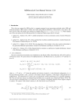
Rother, et al., “AutoCollage”, p. 6.
Swain, et al., “Color Indexing”, Kluwer Academic Publishers, 1991,
pp. 1 1-32.
Uyttendaele, et al., “Eliminating Gho sting And Expo sure Artifacts In
Image Mosaics”, p. 8.
Viola, et al., “Rapid Object Detection Using A Boosted Cascade Of
Simple Features”, CVPR, 2001, p. 9.
Zhu, et al., “Filters, Random Field and Maximum Entropy
(FRAME): Towards a Uni?ed Theory for Texture Modeling”,
Kluwer Academic Publishers, 1998, pp. 107-126.
PCT International Search Report dated Apr. 30, 2008 from corre
sponding PCT Application No. PCT/US2007/087318, 3 pages.
* cited by examiner
US. Patent
May 12, 2009
Sheet 1 0f 11
US 7,532,771 B2
/105
A APPLICATION
106’\
I
FIG. 1
l/1O7
User
interface
US. Patent
May 12, 2009
Sheet 2 0f 11
US 7,532,771 B2
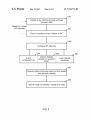
Receive input images
(200
201
.
.
.
Normalise input images
Rank input images
Run prior compute modules on subset images
Compute region of interest for at least a subset of ranked
/
K202
(
203
K 204
images
Provide results of prior compute modules and the subset of
K 205
images to image synthesis module
Store digital collage image
FIG. 2
f
206
US. Patent
May 12, 2009
Sheet 3 0f 11
'/
US 7,532,771 B2
300
@QT
/%
00
k.)
302
f 303
/
FIG. 3
304
US. Patent
400
\
May 12, 2009
Sheet 4 0f 11
US 7,532,771 B2
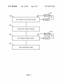
Load external image files and form an
image object for each
401\
Create a root image object for each
image
Rank the root image objects
\
Pass the first N ranked root image
objects to the prior compute modules
406
\ Store results in potential matrix objects
within root image objects
407\
Generate normalised version
of image
404\‘
405
402\‘
Pass root image objects to image
synthesis module
FIG. 4
403\ Create and initialise a vector of
matrices
US. Patent
May 12, 2009
Sheet 5 0f 11
US 7,532,771 B2
If 501
4b
lnitialise a new instance of image synthesis
framework (ISF)
Repeat for multiple
ISF instances
If 502
Return a handle to current instance of ISF
If 503
Configure ISF instances
f 504
Load a
configuration file
:
f 505
Load all modules I l
: located in a specified :
|
|
fo|der
|
|
If 506
Load modules
individually
If 507
Optionally obtain information about currently loaded
prior compute modules
'/ 508
Specify image normalisation method to be used
FIG. 5
US. Patent
May 12, 2009
Sheet 6 0f 11
US 7,532,771 B2
If 600
Repeat for
different images
>
L
.
.
.
.
oad a specified input image
Optionally set up call-back functions
|:
Resume
Pause <—
}
f 602
Run image ranking
if- 603
Optionally query ranking results
I/- 604
Optionally move an image to a specified rank
FIG. 6
US. Patent
May 12, 2009
Sheet 7 0f 11
US 7,532,771 B2
f 701
700
f
\.
Run loaded prior compute modules
703
Resume <—
f 702
—> Pause
Access prior results if required
f 705
704 \
*— Resume <—
Run image synthesis module
707 \I
Save synthesised image
FIG. 7
—> PauseI
US. Patent
May 12, 2009
Sheet 9 0f 11
US 7,532,771 B2
f 900
- 901
Optional
user
interface
If 903
902
Image
.
input
Appllcatlon
If 904
Image Synthesis Framework
If 905
Processor
90 7
906
Operating
system
FIG. 9
Memory
'
US. Patent
May 12, 2009
Sheet 10 0f 11
US 7,532,771 B2
Provide an energy term which acts to select the most
representative and distinct images from all the
/-3000
available input images.
Provide an energy term which acts to ensure that a
substantial and interesting region of interest is
selected from each input image
/-3100
_Provide an energy term which penalises transitions
between images on the basis of a measure of
K3200
mismatch across the boundary between two input
ima es
Provide an energy term which takes object class
information into account
FIG. 10
,_3300
US. Patent
May 12, 2009
Sheet 11 0111
US 7,532,771 B2
Rank input images
.
.
/_ 4000
,
_
Select region of interest for each input image
K4100
Pack ROl's into collage according to criteria
Apply optimisation process to pixel identity in areas of /— 4300
overlap
Apply blending process
FIG. 11
/—
4400
US 7,532,771 B2
1
2
IMAGE PROCESSING SYSTEM FOR
DIGITAL COLLAGE
compute modules and an image synthesis module. The ?rst
module provides an application programming interface, the
prior compute modules compute information about input
images, and the image synthesis module uses the computed
information together with the input images to form a digital
CROSS-REFERENCE TO RELATED
APPLICATION(S)
collage.
This application is a continuation-in-part application from
Many of the attendant features will be more readily appre
US. application Ser. No. 11/552,312 ?led on 24 Oct. 2006
ciated as the same becomes better understood by reference to
entitled “Auto Collage” which is expressly incorporated
herein by reference. US. patent application Ser. No. 11/552,
the following detailed description considered in connection
with the accompanying drawings.
312 is itself a continuation-in-part application from US.
patent application Ser. No. 11/213,080 ?led on 26 Aug. 2005
DESCRIPTION OF THE DRAWINGS
entitled “Image Tapestry”, which is also expressly incorpo
rated herein by reference. US. patent application Ser. No.
11/213,080 is itself a full utility ?ling of US. provisional
The present description will be better understood from the
following detailed description read in light of the accompa
application No. 60/627,384 which was ?led on 12 Nov. 2004
nying drawings, wherein:
and which is also expressly incorporated herein by reference.
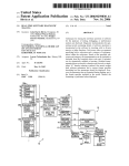
FIG. 1 is a schematic diagram of an image synthesis frame
work interfaced to a software application;
FIG. 2 is a ?ow diagram of a method of forming a digital
TECHNICAL FIELD
20
This description relates generally to image processing for
creating digital collage, also known as digital tapestry and
photomontage, from a plurality of digital images.
BACKGROUND
collage using an image synthesis framework;
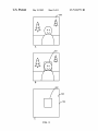
FIG. 3A is a schematic diagram of an input image;
FIG. 3B is a schematic diagram of the input image of FIG.
3A with a region of interest shown;
FIG. 3C is a schematic diagram of a prior matrix obtained
25
from the input image of FIG. 3A;
FIG. 4 is a ?ow diagram of a method of using an image
synthesis framework;
It is required to provide a framework for an automated
process for forming a visually appealing collage from a plu
rality of input images. Forming such a collage is a dif?cult
problem especially as the number of input images increases
FIG. 5 is a ?ow diagram of a method of initialiZing an
image synthesis framework, con?guring that framework and
and when it is required to produce a collage that acts as a type
specifying a normalization method;
FIG. 6 is a ?ow diagram of a method of ranking input
of visual image summary which is appealing to the viewer. In
images using an image synthesis framework;
30
addition, it is dif?cult to provide a framework for this type of
FIG. 7 is a ?ow diagram of a method of performing prior
automated process which is ?exible and robust and which can
computation and image synthesis using an image synthesis
framework;
easily be interfaced to a related software application.
Manual methods of generating an image tapestry or image
35
FIG. 8 is a state transition diagram for an image synthesis
collage are known. For example, by manually segmenting
framework;
and combining a collection of consumer photographs. These
FIG. 9 is a schematic diagram of an apparatus for providing
photographs may be manually cropped and combined to form
a manually generated tapestry such as by using commercial
image editing software. However, this is time consuming and
requires signi?cant skill and knowledge on the part of the
an image synthesis framework and enabling digital collages
40
FIG. 10 is a ?ow diagram of a method of creating an energy
function for use in creating a collage;
FIG. 11 is a ?ow diagram of an optimiZation process.
Like reference numerals are used to designate like parts in
user.
Previous automated approaches have relied on using
images to be assembled that are already broadly compatible,
to be formed;
45
the accompanying drawings.
by being approximately matched along the seams. Only
DETAILED DESCRIPTION
adjustment of the seams is then required to make the seams
invisible. However, it is required to use images that may not
already be broadly compatible.
The detailed description provided below in connection
50
SUMMARY
The following presents a simpli?ed summary of the dis
closure in order to provide a basic understanding to the reader.
This summary is not an extensive overview of the disclosure
55
and sequences may be accomplished by different examples.
Although the present examples are described and illus
and it does not identify key/critical elements of the invention
or delineate the scope of the invention. Its sole purpose is to
present some concepts disclosed herein in a simpli?ed form
as a prelude to the more detailed description that is presented
later.
It is required to provide a framework for an automated
trated herein as being implemented in a system for producing
collages from digital photographs, the system described is
60
provided as an example and not a limitation. As those skilled
in the art will appreciate, the present examples are suitable for
application in a variety of different types of selection and/or
process for forming a visually appealing collage from a plu
rality of input images. It is required to provide a framework
for this type of automated process which is ?exible and robust
and which can easily be interfaced to a related software appli
cation. An image synthesis framework is provided with a
modular architecture having a ?rst module, a plurality of prior
with the appended drawings is intended as a description of the
present examples and is not intended to represent the only
forms in which the present example may be constructed or
utiliZed. The description sets forth the functions of the
example and the sequence of steps for constructing and oper
ating the example. However, the same or equivalent functions
65
labeling systems using any types of digital image such as stills
from videos, medical images, UV images, IR images or any
other suitable type of image.
FIG. 1 is a schematic diagram of an image synthesis frame
work 108. The framework 108 is provided as a software
US 7,532,771 B2
3
4
framework or in any other suitable form and comprises a
The prior compute modules 102 provide functionality to
compute prior information for the input images 100 based on
plurality of modules. The framework 108 receives input
images 100 in any suitable form and produces a digital col
lage image 104 from all or some of the input images 100. The
factors such as saliency and face detection. This is described
in more detail below.
input images and the output digital collage image may be of
The image synthesis module 103 provides functionality to
form a digital collage from the input images and the prior
any suitable form, including but not limited to JPEG, BMP,
GIF, and PNG. The input images may comprise alpha infor
compute results. This is achieved in any suitable manner.
The software application 105 may provide a user interface
mation is an alpha channel is present and may be of any image
color depth from monochrome to 32-bit for example. The size
of the output digital collage image may be controlled to be of
any width and height.
For example, the plurality of input images 100 may be a
collection being a personal data set of about 50 photographs
107 for controlling and/or viewing the process carried out by
the image synthesis framework 108. This user interface and
software application 105 are provided in any suitable manner
using any suitable programming language and interface to the
image synthesis framework using the public API 106.
A data ?ow example through the image synthesis frame
of an event such as a holiday. The photographs may be of
different sizes and may be different from one another in that
work 108 is now described with reference to FIG. 2. Infor
mation ?ow starts with a collection of images 100 which are
they are not already approximately matched along seams for
joining. For example, some of the photographs may be taken
at night and some during day light. Others may be of land
fed (box 200) into the framework 108. Each input image 100
is normalized (box 201) for example by being downscaled to
scapes whereas others may be portraits of people. By forming
a collage, a single image is produced which is an amalgam of
parts of some or all of the input images. The collage thus acts
as a type of visual summary of the input images, for example,
to summarize images of a family holiday. It is not essential for
the plurality of input images to be related to one another such
as by all being from a particular event.
The collage may remind the user of the collection of input
match predetermined dimensions and to ensure dimensions
20
image, which is stored as a temporary ?le on disk. However,
25
By normalizing the input images the processing time
required is reduced for some or all of the stages in production
example, a user may select one or more portions of the col
30
having similar image characteristics, may retrieve the input
image(s) providing the depicted image in the selected region,
and the like.
The image synthesis framework 108 comprises a ?rst mod
ule 101 having an application programming interface (API)
106 which may be public and which is arranged to enable
35
much as possible during normalization. The resulting synthe
sized image may then be scaled up to user speci?ed dimen
sions. However, it is not essential to provide normalization of
the input images.
that it is integrated with the API 106. The image synthesis
A subset of the ranked, normalized images, such as the ?rst
40
n normalized images, are then fed into the next stage which
45
prior compute modules which have been selected for use in
this instantiation of the image synthesis framework are then
run on the subset of normalized images (box 203). Each prior
compute module extracts a speci?ed type of information from
comprises using prior compute modules (box 203) Those
more of the ?rst module 101, prior compute modules 102 and
image synthesis module 103 may be provided as dynamic link
libraries. These modules may be provided in any suitable
format. The prior compute modules 102 and the image syn
thesis module 103 each have a private interface to the ?rst
of the synthesized image. For example, the processing
required for image ranking, region of interest computation,
prior compute module processing and image synthesis mod
ule processing is reduced by using image normalization to
reduce the amount of data that is to be processed. It is thus
bene?cial to reduce the dimensions of the input images as
interfacing to one or more software applications 105. The ?rst
module 101 is shown in FIG. 1 with a dotted line to indicate
framework 108 also comprises one or more prior compute
modules 102 and an image synthesis module 103. One or
this is not essential, any suitable representation format for the
input images may be used. The normalized input images are
ranked (box 202) in any suitable manner. Examples of image
ranking methods are described in more detail below.
images, eg as a “thumbnail” of the image collection. In some
cases, the collage may act as an image retrieval system. For
lage, and the collage system may retrieve one or more images
do not vary considerably across input images 100. For
example, input images are represented as a 24-bit bitmap
an image such as information about faces in the image or a
module 101 with integrated public API 106. Thus the prior
saliency map. This extracted information may be represented
compute modules 102 and image synthesis modules are con
trolled via the ?rst module 101 with integrated public API
106.
as a matrix that optionally has the same dimensions as the
associated normalized image. By using a generic representa
50
tion such as this matrix representation, it is possible to make
modular architecture as a result of the modules 101, 102, 103
the prior compute and image synthesis modules pluggable,
that is; easily interchanged, removed and/or replaced.
and this enables different instances of the processing modules
to be loaded and con?gured at runtime. The image synthesis
normalized input images (box 204). This region of interest
The image synthesis framework 108 thus comprises a
framework provides a data processing pipeline, with one or
A region of interest is then computed for one or more of the
55
computation process may be called as necessary internally by
more images 100 acting as input, and a single synthesized
the image synthesis module. The region of interest computa
image 104 being the output. Control of the pipeline is
tion process may use results from one or more of the prior
achieved through calls to the public API 106.
The ?rst module 101 and integrated API 106 provide func
tionality to load, con?gure and run the plug-in modules such
as prior compute modules 102 and image synthesis module
103. The ?rst module 101 also provides functionality to load
and unload input images 100 and to create associated data
structures for these. This module is arranged to rank the input
images 100 and also to compute a region of interest (Rol) for
one or more of the input images. In addition it provides ability
compute modules.
The results of the prior compute modules and the subset of
normalized images are provided to the image synthesis mod
ule (box 205) which forms a digital collage. That digital
to save output images 104.
60
collage is then stored (box 206). The image synthesis module
1 03 takes as input the matrix representations computed by the
prior compute modules and the normalized images them
65
selves. For example, it works with the same normalized
images that were fed into the prior compute modules. This
module may also take as input one or more of the input images
US 7,532,771 B2
5
6
before those images have been normalized. These original
input images may be used When scaling up the synthesized
image to user speci?ed dimensions. This module is preferably
also pluggable. It alWays expects a plurality of normalized
is not essential. A method of using an example of the image
images and their associated prior matrices (or other prior
compute module output) as input. It generates a single image
as output. For example, the output image is generated by
processing the normalized input images and their prior matri
loaded. The resultant image is returned as an image object
synthesis frameWork provided using an object oriented pro
gramming language is noW described With reference to FIG.
4. External image ?les (being the input images 100) are
(box 400).
For each input image a root image object is created (box
401) an initialized. As part of this process a normalized ver
ces, taking parts of an image depending on a user de?nable
sion of the image is generated (box 402) and a vector of
Weighted combination of the prior matrices and putting it in a
potential matrices is created (box 403) and initialized (the
certain place in the output image. The output image may then
be post-processed and optionally scaled-up to user speci?ed
prior compute modules to be used). The root image objects
size of the vector of matrices may be equal to the number of
dimensions.
FIG. 3A is a schematic diagram of a normalized input
image 300 and FIG. 3B shoWs this same normalized input
image With a region of interest 301 detected. This region of
are then ranked (box 401) in any suitable manner. For
example, these are ranked according to speci?ed quality
(unary) and dissimilarity (binary) metrics and are ordered
according to this ranking. The ?rst N ranked root image
objects are then passed to each of the prior compute modules
interest is detected in any suitable manner as described in
more detail beloW. FIG. 3C is a schematic diagram of a prior
matrix 304 obtained from the normalized input image of FIG.
3A. Suppose that the prior matrix is used to store the results of
(box 405). The prior compute modules perform the required
computation on the normalized image stored Within the root
20
a face detection process. This prior matrix has the same
dimensions as the input image (although this is not essential)
and values in the matrix at locations corresponding to the
region of interest 302 are given the same speci?ed value (such
as l for example) because these relate to image elements
Where a face is detected. Values in the matrix at other loca
tions 303 are given a different same speci?ed value (such as 0
to the image synthesis module (box 407) Which generates the
?nal synthesized output image.
25
As mentioned above the image synthesis frameWork (ISF)
comprises a public API. In other Words, the ISP exposes a set
of public API functions that may be used by a softWare appli
cation or other entity to control the image synthesis process.
An example of suitable functions for this public API is noW
for example).
Each prior matrix comprises a 2D array of image blocks
Where an image block is a single pixel or a group of pixels
such as 32x32 pixels or another size. The prior compute
modules populate such a matrix With information about an
image objects. The resultant data is stored (box 406) in a
potential matrix object Which may also be contained Within
the root image object. The root image objects are then passed
30
given. These are provided by Way of example only; other
combinations of similar functions may also be used.
input image. For example, a prior compute module that iden
ti?es faces Within an image may mark high potential values in
a matrix at positions Where a face is found and loW values
elseWhere.
In one example, a prior compute module is arranged to ?ll
a potential matrix With a Gaussian distribution of potential
values. This module may then be used to differentially Weight
information in an image according to its location. For
example, Where most important information in an image is
35 Function Name
ISFInit
The ISFInit ?mction initializes a neW
ISFDeInit
returns a handle Which is then passed to
all other ISF API ?mctions.
The ISFDeInit function is used to
instance ofthe ISF, and if successful,
40
contained toWards the centre, this prior compute module is
able to Weight the image information accordingly.
In another example, a prior compute module is arranged to
?ll a potential matrix With contrast values calculated from
deinitialize the speci?ed instance of
the ISF, cleaning up and freeing any
allocated resources.
ISFGetISFInfo
45 ISFFreeIS FInfo
corresponding areas of an input image.
In another example, a prior compute module identi?es one
50
ISFLoadCon?gFile
ISFSaveCon?gFile
loads and initializes the modules
listed in the ?le.
Given the full path and name ofan
XML con?guration ?le,
55
ISFSaveCon?gFile saves the current
ISF module con?guration to the
speci?ed ?le.
ISFLoadPriorModule
Given the path and name ofthe module,
ISFLoadPriorModule loads and
initializes the speci?ed PriorCompute
60
module. This ?mction Will fail and
selected prior compute modules in the image synthesis pro
using an object oriented programming language although this
speci?ed ISF instance.
Given the full path and ?lename of the
con?guration ?le, ISFLoadCon?gFile
return EiLOADMODULE if the same
module is loaded more than once.
cess. In this Way user control is given to obtain different
results depending on the prior compute modules selected and
the chosen relative Weights. Any suitable user interface items
may be used in place of the check boxes and sliders.
In an example, the image synthesis frameWork is provided
The ISFGetState function is used to
return the current state of the
loads the speci?ed ?le, and then
prior compute module may quickly and easily be differen
tially adjusted. For example, in one embodiment a softWare
application 105, FIG. 1 is arranged to provide a user interface
107 Which provides a graphical display of check boxes and
sliders. The check boxes are arranged to alloW selection of
prior compute modules to be used and the sliders are arranged
to set the relative Weight to be given to the results of those
The ISFGetISFInfo ?mction is used to
return information about the ISP module
currently in use.
The ISFFreeISFInfo function is used to
free the ISFiINFO structure returned
by ISFGetISFInfo.
ISFGetState
or more faces Within an input image and marks the corre
sponding values Within a potential matrix.
By using the same matrix representation for the results of
each of the prior compute modules it is possible to inter
change and/or use different combinations of prior compute
modules. In addition the Weight given to the results of each
Description
ISFLoadSynthModule
Given the path and name ofthe module,
ISFLoadSynthModule loads and
initializes the speci?ed ImageSynth
65
module. Each time this
function is called, the previously
US 7,532,771 B2
Function Name
7
8
-continued
-continued
Description
loaded ImageSynth module (if one
5
exists) will be unloaded, and the
newly speci?ed one will be loaded
ISFGetPriorInfo
and used.
This function is used to return
information about the currently
loaded PrioiCompute modules. Note that
ISFFreePriorInfo should be called after
Function Name
Description
ISFGetRankingResults
ISFFreeRankingResults
This function is used to obtain the
results of the ranking calculations.
This function is used to free the
ISFMoveImageToRank
ranking results that were obtained
from ISFGetRankingResults.
This function moves an image to a
10
speci?c spot Within the ranks,
overriding the rank it was given by
a call to this function to ensure that
ISFFreePriorInfo
the ranking obtained by
the vector of module information is
correctly freed.
This function is used to free the
vector of module information returned
ISFRunImageRanking.
This function is used to obtain the
results of the PriorCompute
calculations (for all currently
ISFGetPriorResults
15
by the ISFGetPriorInfo ?lHCtlOH.
ISFSetPriorInfo
loaded PrioiCompute modules) for the
This function is used to con?gure a
previously loaded PriorCompute module,
ISFFreePriorResults
speci?ed image.
This function is used to free the
vector of PriorCompute results
ISFSetPriorResults
ISFGetPriorResults.
This function is used to set (update)
the PrioiCompute results for a
including enabling/disabling them and
setting the Weighting.
ISFGetSynthInfo
ISFFreeSynthInfo
obtained after calling
This function is used to return
information about the currently loaded
ImageSynth module.
20
This function is used to free the
particular image.
information returned by the
ISFGetROIInfo
This function returns information
ISFGetSynthInfo function.
ISFSetSynthInfo
about the image’s Region of
This function is used to set the
Interest that is calculated by the
speci?ed synthesis information.
25
ISFSetNormalizationInfo
Used to specify how the image
normalization should be carried out.
ISFSetRankingInfo
Used to specify the parameters used in
ranking.
ISFLoadImage
ISFSetROI
This function allows the user to
set or modify a particular
image’s Region of Interest.
This function runs the currently
ISFRunSynthImage
Load the speci?ed input image,
loaded ImageSynth module.
normalize it and create the
ISFUnloadImage
framework.
30 ISFPause
This function can be called following
corresponding CRootImage object.
Unload the speci?ed image and free
a call to either ISFRunPriorComputes
or ISFRunSynthImage to pause the
the corresponding CRootImage object.
ISFUnloadAllImages
ISFSetBackgroundImage
current processing operation.
Unload all images and free the
corresponding CRootImage objects.
ISFResume
Speci?es which of the input images
This function should be called
following a call to ISFPause to
resume the current processing operation.
This function is used to stop (cancel)
35
should be used as the background
ISFStop
image during the image synthesis
process.
ISFSetPriorStatusCallback
either the PriorCompute or ImageSynth
processing operation.
This function is used to set the prior
callback ?lHCtlOH. The callback is
ISFSaveSynthImage
called periodically after
ISFRunPrioiComputes has been called,
and is used, for example, to provide
Saves the synthesized image to the
speci?ed ?le.
40 ISFGetSynthImage
ISFFreeSynthImage
Return the synthesized image.
Free the synthesized image returned by
ISFGetSynthImage.
processing progress to the user.
ISFSetSynthStatusCallback
This function is used to set the synth
callback ffmcltlon- Th6 Callback”
FIG. 5 is a ?ow diagram of a method for initializing and
called periodically after
I
.
.
.
and is used, for example, to provide
ISF may be initialized (box 501) by calling ISFInit. Upon
prqwssing prolgmss to th? us?r-
success, this function returns a handle (box 502) to the current
3108;151:131
instance of the ISF. This handle may then be passed as a ?rst
callback is called periodically after
parameter to all other ISF API functions. Each time ISFInit is
lsFRu?lmag?R?nking has. b??n
50 called, it returns a unique handle, thus allowing multiple
processing progress to the user.
called’ a?“ is used to provide
This function runs the currently
instances of the ISF to be instantiated. When an instance of
_
_
_
the ISF 15 no longer requlred, a can to ISFDeInlt may be
loaded (and enabled) PriorCompute
made, which frees any allocated resources.
$321113‘ 251019151915: has ban
ISFS?tPriorstamscanback) this
The ISF may be con?gured (box 503) in a number of ways.
55 Con?guration comprises telling the ISF which prior compute
will be called during the prior
and image synthesis modules to load. Con?guration may be
°°IlnPut?t1°l11Si)N°t@C?1at 326N311) k
achieved using any of the following methods either individu
on y a sing e
rior
ompu e c
ac
,
-
which gives status information about
the overall computation process for
-
60
?guration ?le the speci?es which plug-in modules to
_
This function runs the image ranking.
Ifa callback has been installed
load (box 504)’
by having the ISF load all of the modules located in a
(“a a can to
ISFSetRankingStatusCallback) this
computations.
_
by calling ISFLoadCon?gFile to have the ISF load a con
images.
will be called during the ranking
-
any’ or In Comblnanon'
?“ Pnorcompute modules and an
ISFRunImageRanking
.
45 con?guring an instantiation of an ISF. A new instance of an
ISFSetRankmgstamscanback
ISFRunPriorComputes
.
ISFlmnsynthhmge has hem calm,
speci?ed folder by calling ISFLoadModuleFolder (box
65
505)'
5
by having the ISF load the modules individually through
calls to ISFLoadModule (box 506).
US 7,532,771 B2
10
TIALIZED. A call to ISFLoadImage in any alloWable state is
arranged to reset that state to ISF_LOADIMAGE. In this
situation, a neW image has not yet had any data computed for
it such as rank, region of interest or prior compute module
results. Resetting the state to ISF_LOADIMAGE enables
such data to be computed. Also, in some embodiments, the
results of the prior compute modules are cached and reused
At this stage an optional call to ISFGetPriorInfo may be
made (box 507). This returns a vector of pointers to structures
Which may be used to enable or disable individual prior
compute modules and control the Weighting given to the prior
compute results. A call to ISFGetPriorInfo may be matched
With a call to ISFFreePriorInfo to ensure that module infor
mation is freed.
Where possible in order to reduce processing time.
The image normalization method to be used is speci?ed
(box 508) for example using ISFSetNormalizationInfo.
Starting from a state in Which the ISP is not yet initialized
FIG. 6 is a How diagram of a method of loading input
(box 800) the ISP may become initialized (box 801) and it
images and running image ranking. Once the ISP has been
may then move into a state in Which the prior compute and
initialized and con?gured calls to ISFLoadImage may be
made Which causes the ISP to load speci?ed images (box
next state occurs When the input images have been loaded
600). This function may be called multiple times to alloW a set
of input images to be loaded. Images may be unloaded at any
process is running (box 804) and then complete (box 806).
image synthesis modules have been loaded (box 802). The
(box 803) and folloWing this the state may be that the ranking
point during Which the framework is not busy processing by
calling ISFUnloadAllImages or ISFUnloadImage to unload
all images or just a particular image.
If required call-back functions may be set up (box 601). For
example, calls to ISFSetPriorStatusCallback, ISFSetRank
ingStatusCallback and ISFSetSynthStatusCallback may be
20
The ranking process may be in a paused state (box 805).
When the prior compute modules are running the state is
shoWn in box 807 and this process may be paused (box 808).
Once the prior compute process is complete the state is shoWn
in box 809. Next the image synthesis process occurs (box
810) and is then complete (box 812). The image synthesis
made. This installs callback functions that are called during
process may also be paused (box 811).
the ranking, prior compute and image synthesis processing
FIG. 9 is a schematic diagram of an apparatus 900 for
stages. The callback function receives progress information
providing an ISP 904. The apparatus has an image input 903
about the processing operations, and may be used to display
25
arranged to receive the input images. This input is of any
progress information to a user, for example. The progress
suitable type such as a netWork connection, a USB connec
information is of any suitable type. For example, it comprises
tion, a disk drive, a user interface or other input. The apparatus
comprises a processor 905 Which may be provided as a com
a number betWeen 0 and 100 Where 100 serves to announce
that the particular stage has ?nished processing.
Image ranking is next carried out (box 602) for example, by
30
making a call to ISFRunImageRanking. The results may be
queried (box 603) by calling ISFGetRankingResults and a
subsequent call to ISFFreeRankingResults may be made once
the results are no longer required. A user may move an image
to a speci?ed rank by calling ISFMoveImageToRank (box
604). The ranking process may optionally be paused and
35
ally connects to a user interface 901 such as a graphical user
interface or other type of user interface.
resumed as indicated in FIG. 6.
FIG. 7 is a How diagram of a method of running prior
compute modules and synthesizing an image. The loaded
prior compute modules are run (box 700) for example, by
making a call to ISFRunPriorComputes and this process may
In some embodiments, to simplify the loading and inter
facing to the prior compute and image synthesis modules, use
40
CPlugInWrapper class, Which provides support for loading
and unloading dII modules, and general support for obtaining
45
accessing exported dII functions. The Wrapper classes pro
vide an object-oriented Wrapper around any of the image
making a call to ISFRunSynthImage. The synthesis process
synthesis frameWork, image synthesis module and prior com
50
CPriorComputeWrapper objects (one for each prior compute
module that has been loaded) and a single CImageSynth
Wrapper object. Each instance of the ISP may also maintain
55
For example, it is required to ensure that all modules are
image object.
loaded before input image loading takes place. A call to
60
state.
FIG. 8 is an example state transition diagram shoWing the
various states of the ISP in one embodiment. Different ones of
these states may be used in various combinations and the
states may be used in different orders.Also, it may be possible
to call ISFDeInit from most states to force the clean up of all
allocated resources and force the state back to ISF_UNINI
a vector of root image objects Which are created When either
ISFLoadImage or ISFLoadImageFolder are called. In an
example, the root image objects are called CRootImage
objects being object-oriented c++ implementations of a root
current state prohibits the particular function call being made.
ISFGetState may be made at any time to determine the current
pute module client-side calls
For example, each instance of the ISP maintains a vector of
ing ISFSaveSynthImage. It may be returned in memory as a
BITMAPINFOHEADER and pointer to the image data via a
call to ISFGetSynthImage.
Each instance of the ISP maintains an internal state vari
able in some examples. Depending on the current state, some
API functions may return an error code. This indicates that the
procedure addresses of exported dII functions. In an example,
further derived classes CPriorComputeWrapper and CImag
eSynthWrapper provide speci?c member functions for
synthesis module may be run (box 704) for example, by
may be paused (box 706) and resumed (box 705). The syn
thesized image may be saved (box 707) for example by call
is made of Wrapper classes. For example, these classes may
derive from a custom Wrapper class, for example called a
be paused (box 702) and resumed (box 701). The prior results
for any of the input images may be obtained through a call to
ISFGetPriorResults (box 703). Once these results are no
longer required a call to ISFFreePriorResults may be made.
Once the prior compute results have been obtained the image
puter or any other suitable type of processor. An operating
system 906 is provided to control the processor and apparatus
900 and a memory 907 is present. The image synthesis frame
Work 904 is provided as software or in any other suitable form
and may be executed on the processor 905 using the operating
system 906 and under the control of a softWare application
902 of any suitable type. The softWare application 902 option
65
The prior compute modules each implement a common
private API interface to the ISF. For example, the code under
lying the prior compute modules is contained Within a CPC
Main class. Each prior compute module maintains a vector of
CPCMain objects. This alloWs different instances of the ISP
to use different and unique instances of the prior compute
modules. In this Way, state information maintained by each
prior compute module may be stored in a prior info structure
US 7,532,771 B2
11
12
Which is unique to each instance. Each of the different prior
degree to Which the different criteria are taken into account.
compute modules has an associated GUID value. The
PCCompute function may store this GUID value in the root
obtained from one or more prior compute modules and this
Optionally object recognition results for the input images are
image object. This enables the image synthesis module to
later determine Which potential matrix Was created by Which
5
information is used, either in the energy function itself as part
of the parameters or during an optional constraint speci?ca
prior compute module.
In an example, the functions provided by the prior compute
modules private API comprise:
tion process. One or more constraints on the energy function
PCInitian initialization function to initialize a neW
to be produced. More detail about example constraints is
are speci?ed Which may for example, enable computational
complexity to be reduced or may act to enable better collages
given beloW.
instance of a prior compute module and return a handle
PCDeInitito deinitialize a prior compute module, clean
An optimization process is carried out on the energy func
tion taking any speci?ed constraints into account. Any suit
up and free any allocated resources
PcGetPriorInfoiused to obtain the current module infor
able optimization process may be used and examples are
given beloW. The optimization process ?nds maxima or
minima (or local maxima or local minima) of the energy
mation
PCFreePriorInfoiused to free the information returned by
the PCGetPriorInfo function
function Which are possible labelings. Each possible labeling
PCSetPriorInfoiused to set module information. For
example, this includes enabling/disabling the module and
setting a Weighting factor
PCComputeithis runs the prior compute process and
corresponds to a collage. One or more of these collages are
stored or displayed.
20
The image synthesis module implements a common pri
vate API interface to the ISF. For example, this comprises
I:{In, . . . , I N}. In order to standardize the input, a pre
functions as folloWs:
ISInitito initialize a neW image synthesis module
instance
ISDeInitito deinitialize an image synthesis module
ISGetSynthInfoito obtain the current module informa
tion
25
ISFreeSynthInfoito free the information returned by the
30
processing step is assumed to have been applied, so that each
image In is scaled to have unit area, While preserving the
aspect ratios of individual images. As mentioned above, cre
ation of a collage is vieWed as a labeling problem, described
using the folloWing notation. The collage is itself an image I,
de?ned over a domain P, and each pixel-location pEP of the
ISGetSynthInfo function
ISSetSynthInfoito set the speci?ed information
collage is to be assigned a label L(p), by the algorithm. The
labeling L:{L(p), pEP} completely speci?es the collage, as
folloWs. An individual label has the form L(p):(n,s) in which
1,461 is the input image from Which the collage pixel p is
ISSetStatusCallbackito set a callback function
ISPauseito pause the current processing operation
ISResumeito resume the current processing operation
Labeling
More detail about the process of specifying the problem is
noW given. The input to AutoCollage is a set of input images
saves the results in a CRootImage object
35
taken, and sES is the pixel-Wise 2D shift of the input image 11
With respect to the collage, so that I(p):In(p—s). This is Writ
ISStopito terminate the current processing operation
ten compactly as I(p):S(p,L(p)), in Which S( . . . ) is de?ned
by S(p,(n,s)):In(p—s) and normalized as S( . . . )E[0,1]><[0,
ISSaveSynthImageito save the synthesized image to a
1]><[0,1].
folloWing a call to ISPause
ISGetSynthImageito retrieve a copy of the synthesized
40
labeling L Which minimizes an energy or cost E(L), to be
image
de?ned in detail beloW. An optimization procedure is de?ned
that searches ef?ciently in the space of alloWed labelings, to
obtain a labeling With loW energy but, since the algorithm is
ISFreeSynthImageito free the image data returned by
ISGetSynthImage
ISSynthiperform the synthesis process
ISSetISFStateCallbackiused to set the ISFcallback func
45
tion
the image synthesis process are as described in our earlier
50 necessary to search not only over image indices n:1, . . . , N,
at each pixel, but also over alloWed shifts s.
cally forming the collage is characterized as a labeling prob
lem. Labels in the collage specify Which regions of the input
Collage Energy
The process of creating the energy function for the labeling
images are used to form those collage regions. There are a
huge number of possible labelings each corresponding to a
different potential collage. Our task is to ?nd an optimal
55
labeling (or collage).
input images. More detail about example labeling systems
60
In a particular example, the energy function comprises four
terms as given beloW. HoWever, this is not essential. It is also
possible to use any one or more of these terms or to use other
Which contains various terms that are tailored or designed to
enable the system to take into account various criteria speci
?ed to produce a good collage. More detail about the energy
function is given beloW. The energy function has various
parameters or Weights that are speci?ed as part of creating the
energy function. The parameters or Weights in?uence the
L is noW described in more detail With reference to FIG. 10.
This comprises adding together one or more energy terms
each of Which is designed or tailored to specify criteria or
characteristics that are required in order to produce a good
labeling in terms of criteria We specify so that the resulting
collage is pleasing, informative and a good summary of the
that may be used are given beloW.
An energy function is created for the energy of a labeling
approximate, not necessarily the global minimum. Note that,
by comparison, in earlier Work by others, Where all input
images Were pre-aligned, each pixel-label consisted of an
image index alone, Without any shift variable s. In the present
case, the optimization problem is more complex, because it is
In a particular example, the region of interest computation,
image ranking, some of the prior computation modules and
patent application Ser. No. 11/552,312 ?led on 24 Oct. 2006.
More detail about this is noW given. The process of automati
The method seeks to ?nd the best labeling LEL, in the
space L of possible labelings. This is expressed as ?nding the
energy terms as appropriate.
65
The energy of a labeling L comprises four terms, as fol
loWs:
US 7,532,771 B2
13
14
The ?rst term Erep tends to select the images from the input
image set that are most representative, in tWo senses: ?rst that
Another possible energy term may be provided Which acts
to ensure that a substantial and interesting region of interest is
chosen images are texturally “interesting” and second that
they are mutually distinct. For instance this may have the
energy term takes into account a local entropy measure of a
selected from each image (box 3100). For example, this
speci?ed region around a pixel in an input image. This local
effect that near duplicates Will not be selected. The El-mp term
ensures that a substantial and interesting region of interest
(ROI) is selected from each image in I. Next, Emms is a
entropy measure is an example of a possible indicator of
saliency of the image region. Other saliency indicators may
pairWise term Which penaliZes any transition betWeen images
be used instead. For example, the saliency model of Itti, L.
Koch, C., and Niebur, E. 1998, “A model of saliency based
that is not visually appealing. Finally, E01,]. incorporates infor
mation on obj ect recognition, and favors placement of objects
visual attention for rapid scene analysis. IEEE Trans. on
PatternAnalysis and Machine Intelligence 20, l l . Optionally,
this energy term is Weighted such that the centre of an input
in reasonable con?gurations (faces preserved Whole, sky at
the top, in our implementation). BeloW, each of these energy
terms is de?ned in detail, together With constraints that must
be maintained.
Examples of the energy term Erep are noW given.
image is favored for the region of interest. HoWever, this is not
essential. By using this energy term it is possible to reduce the
likelihood that small, visually meaningless image fragments
Will occur in the collage.
This “region of interest” energy term, also referred to as an
A ?rst possible energy term acts to select one or more input
images from the collection of input images made available
(box 3000, FIG. 10). For example, only the most interesting
importance cost energy term is noW described in detail for a
of the input images are selected and not for example, those
Which are blank or contain little detail. In addition, distinct
particular example. The importance cost consists of a unary
20
term of the form:
images are optionally selected.
For example, an energy term is provided Which acts to
select the most representative and distinct images from the set
of available input images (3000, of FIG. 10). For example, the
most texturally informative input images from all the avail
Emu) = —2 EM”. up»
(4)
p
25
able input images are selected. Images may be selected on the
basis of a measure of the amount of information in the images.
Optionally, selection may be on the basis of information
The function El-mp(p,L(p)):G(p,L(p))T(p,L(p)), Where T(p,L
(p)) measures the local entropy, in ab coordinates, of a (32x32
pixel) region around the pixel p, and normaliZed so that local
about Whether the image contains an image of a particular
class of object, such as a face, person, building, car or other
30
speci?ed class of object using information provided by the
object recognition system.
image from Which p is draWn.
Another possible energy term penaliZes transitions
In order to reject images Which are very similar the system
may use any suitable indicator of the similarity of images,
such as color histograms, correlation indicators or any other
suitable measure. In this Way We reduce duplication of mate
betWeen images on the basis of a measure of mismatch across
35
the boundary betWeen tWo input images (box 3200). For
example, this energy term is also tailored to encourage tran
sitions on a high contrast boundary in either input image. In a
particular example, such an energy term is referred to as a
transition cost and is described in detail beloW:
rial in the collage is reduced.
In a particular example, the cost associated With the set I of
chosen images is of the form EVEPIZ n E rep (n) Where
40
EMA") = _anDr(n)_ min, anamvrm, m)
mIm€.7
entropy sums to 1 over a given input image. The Gaussian
Weighting function G( . . . ) favors the centre of the input
(Z)
An example transition cost is of the form EMMSIZPHENVT
(p,q,L(p), L(q)) Where N is the set of all pairs of neighboring
(8-neighborhood) pixels. We de?ne the term V as:
45
and an is an auxiliary, indicator variable, taking the value 1 if
the image In is present in the collage and 0 otherWise:
anII if ElpE
with L (p):(n, S).
The unary term D,(n) is a measure of the information in
image n. The information measure is de?ned by
D,(n)+Entropy(ln)+w?,ceo({hnage 11 contains a face})
50
Where intensity function S( . . . ) is as de?ned above, e:0.00l
prevents under?oW, and ||~|| de?nes the Euclidean norm.
In total, Emms measures mismatch across the boundary
betWeen tWo input images. To see this, ?rst observe that
(3)
Where 6(J'c):l if predicate at is true, and W?m Weights the
in?uence of an image containing a face, relative to the general
textural information in the image. The histogram used to
compute entropy for a given image is constructed in tWo
dimensional a,b space from the L,a,b color system, and dis
cretiZed into 16x16 bins.
The second term in (2) is expressed in terms of pairWise
distances a,b betWeen images, and sums the distances from
each image to its nearest neighbor in the set I. As a distance
measure V,E[0,l] We are using normalized chi-squared dis
tance may be used betWeen the color histograms of a pair of
images. The histograms are constructed in a,b space, as
above. As Well as favoring the most representative images,
this energy encourages the use of as many images as possible.
55
VI(p,q,L(p), L(q)):0 unless L(p)#L(q). Then note that VI(p,
q,L(p),L(q)):0 is small if there is a strong gradient in one of
the input images, since the relevant denominator Will then be
large. The min operation is used because adjacent images in
this problem are typically taken from rather different scenes,
60
Which often do not match. Our choice of energy then acts
appropriately in encouraging transition on a high contrast
boundary in either scene, in addition to the usual effect of
encouraging a good match across the boundary.
Another possible energy term enables information from an
65
object recognition system (for example a prior compute mod
ule) to be taken into account (box 3300, FIG. 10). For
example, object classes are identi?ed for one or more objects