1
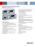
Digital Phosphor Oscilloscopes — DPO7000C Series
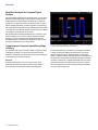
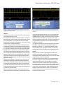
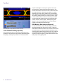
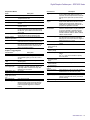
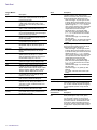
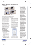
Digital phosphor technology enables greater than 250,000 wfm/s waveform capture rate
and real-time color grading on the DPO7000C Series.
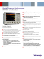
Eye Diagram triggering using optional Visual Trigger.
Digital Phosphor Technology
The DPO7000C Series' digital phosphor technology provides you with fast
insight into the real operation of your device. Its fast waveform capture
rate – greater than 250,000 wfm/s – gives you a high probability of quickly
seeing the infrequent problems common in digital systems: runt pulses,
glitches, timing issues, and more.
Waveforms are superimposed with one another and waveform points are
color coded by frequency of occurrence. This quickly highlights the events
that occur more often over time or, in the case of infrequent anomalies,
occur less often.
With the DPO7000C Series, you can choose infinite persistence or variable
persistence, determining how long the previous waveform acquisitions stay
on-screen. This allows you to determine how often an anomaly is occurring.
Visual Trigger (Optional)
The Visual Trigger option adds an additional dimension to the standard
trigger system that provides an intuitive method of triggering based on
shapes in the oscilloscope’s graticule. It enables the user to define shapes
on the oscilloscope’s display that qualify trigger events for the incoming
signals. Areas can be created using a variety of shapes including triangles,
rectangles, hexagons, or trapezoids to fit the area to the particular trigger
behavior desired. Once shapes are created on the oscilloscope’s display,
they can be positioned and/or re-sized dynamically while the oscilloscope
is in Run mode to create ideal trigger conditions. Visual Trigger can be
combined with the standard triggers and act as a Boolean logic qualifier
for the “A” and “B” events.
Serial Triggering and Analysis (Optional)
On a serial bus, a single signal often includes address, control, data, and
clock information. This can make isolating events of interest difficult. The
DPO7000C Series offers a robust set of tools for debugging serial buses
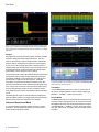
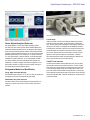
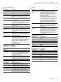
Triggering on a specific OUT Token packet on a USB full-speed serial bus. A bus
waveform provides decoded packet content including Start, Sync, PID, Address, End
Point, CRC, Data values, and Stop.
with automatic trigger and decode on I2C, SPI, RS-232/422/485/UART,
CAN, LIN, and USB 2.0, and decode for MIPI D-PHY DSI-1 and CSI-2
serial buses.
Serial Triggering
Trigger on packet content such as start of packet, specific addresses,
specific data content, unique identifiers, etc. on popular serial interfaces
such as I2C, SPI, RS-232/422/485/UART, CAN, and USB 2.0.
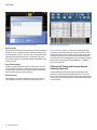
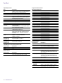
Bus Display
Provides a higher-level, combined view of the individual signals (clock, data,
chip enable, etc.) that make up your bus, making it easy to identify where
packets begin and end and identifying subpacket components such as
address, data, identifier, CRC, etc.
www.tektronix.com
5