1
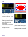
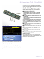
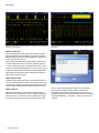
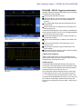
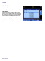
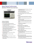
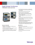
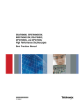
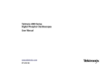
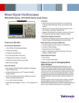
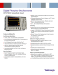
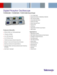
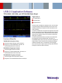
USB 2.0 Application Software
TDSUSB2, SR-USB, and DPO4USB Data Sheet
Applications
Low-speed USB 2.0
Full-speed USB 2.0
High-speed USB 2.0
Tektronix provides comprehensive, integrated tool sets to serve the needs
of engineers designing USB-based embedded systems as well as those
validating the physical-layer compliance of USB 2.0 serial devices to the
USB 2.0 standards.
The Tektronix TDSUSB2 USB 2.0 Compliance test application and selected
Tektronix oscilloscopes provide one-button compliance testing for USB 2.0
devices as specified by the USB-IF. TDSUSB2 automates the compliance
testing and allows engineers to perform the required tests efficiently and
reliably right on their bench.
Features & Benefits
TDSUSB2 USB 2.0 Compliance Testing
Automated Compliance Testing for USB 2.0 Verification
Designed for use with MSO/DPO5000, DPO7000, and
DPO/DSA/MSO70000 Series Oscilloscopes
SR-USB USB 2.0 Triggering and Analysis
Automated Trigger and Decode for USB 2.0
Designed for use with the MSO/DPO5000, DPO7000C, and
DPO/DSA/MSO70000C Series Oscilloscopes
DPO4USB USB 2.0 Triggering and Analysis
Automated Trigger, Decode, and Search for USB 2.0
Designed for use with the MSO/DPO4000 Series Oscilloscopes
The Tektronix MSO/DPO4000 Series oscilloscopes with the DPO4USB
Serial Application Module and MSO/DPO5000, DPO7000C, and
DPO/DSA/MSO70000C Series oscilloscopes with the SR-USB application
simplify analysis of USB 2.0 waveforms when validating and debugging
USB-based embedded systems. DPO4USB offers automated trigger,
decode, and search for low-speed, full-speed, and high-speed USB buses,
enabling fast and efficient validation and debug.
Data Sheet
TDSUSB2 compliance test results.
TDSUSB2 Automated USB eye diagram analysis.
TDSUSB2 – Automated USB 2.0 Physical
Layer Compliance Testing
USB compliance testing has some unique measurement challenges:
Designers must quickly and accurately perform all compliance tests
recommended by the USB Implementers Forum, Inc. (USB-IF) before
they can affix the “certified” USB-IF logo to their packaging
Characterization of these electrical signals includes mask testing and
parametric testing, for low-speed, full-speed, and high-speed hosts,
devices, and hubs
Signal speeds range from 1.5 Mb/s (low-speed) to 480 Mb/s
(high-speed)
The TDSUSB2 provides automated compliance testing for USB 2.0 serial
bus verification, including:
Fully compliant with USB-IF tests for USB 2.0 compliance testing
Automated eye diagram analysis verifies signal quality
Automated oscilloscope setups for various tests eliminate
time-consuming manual setups
Measurement Select menu for the Signal Integrity test.
Comprehensive test fixture enables quick setup and signal access for a
wide range of tests
Quick Pass/Fail tests substantiated with results make the TDSUSB2
application the preferred solution for USB 2.0 physical-layer validation.
In-depth analysis is possible with the statistical information about the tests
performed. The user-defined measurement limits also help to perform
tolerance testing on a design.
High-speed tests: Signal Quality, Receiver Sensitivity, Chirp, Reset,
Resume, Suspend, Packet Parameter, and Monotonicity tests
Automatic rise and fall time measurements simplify tests
Automatic deskew for accurate measurements
Online help fully documents test procedures
User-configurable report formats for customization
User-configurable measurement limits for tolerance testing
2
www.tektronix.com
TDSUSB2 can be downloaded from www.tektronix.com and with the option
license you can easily install the software on your oscilloscope. After
installation, the application is accessible from the menu bar of the Tektronix
Windows oscilloscopes. The user manual and other documents are copied
at the application installation location on the oscilloscope's hard drive.
USB 2.0 Application Software — TDSUSB2, SR-USB, and DPO4USB
The test fixture is an accessory of TDSUSB2, and is ordered separately.
The USB-IF logo-tagged 6 in. AB cable is shipped along with the test fixture.
SR-USB – USB 2.0 Triggering and Analysis
Debugging USB-based embedded systems designs provides some
complex measurement and analysis challenges:
Capturing specific USB addresses and data
Displaying the elements of the USB message in an understandable
format, in a variety of formats, for a wide variety of engineers and
technicians
Time-correlating USB messages with analog and digital signals in the
embedded system
Capture long time windows of USB traffic and then find specific events
within the acquired data
The optional SR-USB application software, installed in an MSO/DPO5000,
DPO7000C, or DPO/DSA/MSO70000C Series oscilloscope, provides a
robust set of tools for debugging embedded systems with USB 2.0 serial
buses, including:
Automated serial triggering and decode for low-speed, full-speed, and
high-speed USB 2.0 signals
TDSUSBF USB 2.0 Test Fixture.
Trigger on all the critical elements of a USB bus such as address, data,
etc.
Decode all the critical elements of each USB message. No more
counting 1s and 0s!
Search through long acquisitions using user-defined criteria to find
specific messages
Event table shows decoded serial bus activity in a tabular, time-stamped
format for quick summary of system activity
USB Serial Triggering
Trigger on packet content such as sync, reset, suspend/resume, token
(address) packets with specific address and endpoint, specific data content,
handshake packets, special packets, and errors.
Triggering on a specific PID on a USB full-speed bus. A complete set of triggers, including
triggers for specific token (address) and data packet content, ensures you quickly capture
your event of interest.
USB 2.0 Compliance Test Fixtures
A comprehensive compliance test fixture provides a probing solution for
the Signal Quality, Inrush Current, Drop and Droop, Receiver Sensitivity,
and Impedance Measurement test. Connectors are available for a data
generator and Tektronix DSA8200 sampling oscilloscope with TDR module.
www.tektronix.com
3
Data Sheet
Color-coded decoded display of low-speed USB bus, showing Sync, PID, CRC, and Stop
components of the serial signal.
High-speed USB decoded display, automatically displaying bus content in any of several
digital formats.
USB Serial Decode
The SR-USB application provides a higher-level, combined view of the
individual signals that make up the USB bus, making it easy to identify
where packets begin and end and identifying subpacket components such
as sync, PID, data, CRC, errors, etc.
Are you wasting time manually decoding the waveform? Tired of having
to visually inspect the waveform to count clocks, determine if each bit is
a 1 or a 0, combine bits into bytes, and determine the hex value? Let the
oscilloscope with the SR-USB application do it for you! Once you've set up
a USB bus, the MSO/DPO5000, DPO7000C, or DPO/DSA/MSO70000C
Series will decode each packet on the bus, and display the value in Hex,
Binary, or ASCII in the bus waveform.
USB 2.0 Event Table
In addition to seeing decoded packet data on the bus waveform itself, you
can view all captured packets in a tabular view much like you would see in
a software listing. Packets are time stamped and listed consecutively with
columns for each component (Time, PID, Address, Payload, and Errors).
USB 2.0 Search
USB packet content triggering is very useful for isolating the event of
interest, but once you’ve captured it and need to analyze the surrounding
data, what do you do? In the past, users had to manually scroll through
the waveform counting and converting bits and looking for what caused
4
www.tektronix.com
USB decoded Event table showing all packet information with time-stamp information.
the event. With the SR-USB application installed, you can enable the
oscilloscope to automatically search through the acquired data for
user-defined criteria including serial packet content. Each occurrence is
highlighted by a search mark. Rapid navigation between marks is as simple
as pressing the Previous (←) and Next (→) buttons on the oscilloscope
front panel.
USB 2.0 Application Software — TDSUSB2, SR-USB, and DPO4USB
DPO4USB – USB 2.0 Triggering and Analysis
Debugging USB-based embedded system designs provides some complex
measurement and analysis challenges:
Capturing specific USB addresses and data
Displaying the elements of the USB message in an understandable
format, in a variety of formats, for a wide variety of engineers and
technicians
Time-correlating USB messages with analog and digital signals in the
embedded system
Capture long time windows of USB traffic and then find specific events
within the acquired data
The optional DPO4USB application module, installed in an MSO/DPO4000
Series oscilloscope, provides a robust set of tools for debugging embedded
systems with USB 2.0 serial buses, including:
Triggering on a specific PID on an USB FS bus. A complete set of triggers, including
triggers for specific Token (address) and data packet content, ensures you quickly capture
your event of interest.
Automated serial triggering and decode for low-speed, full-speed, and
high-speed USB 2.0 signals
Trigger on all the critical elements of a USB bus such as address, data,
etc.
Decode all the critical elements of each USB message. No more
counting 1s and 0s!
Search through long acquisitions using user-defined criteria to find
specific messages
Event table shows decoded serial bus activity in a tabular, time-stamped
format for quick summary of system activity
USB 2.0 Serial Triggering
Trigger on packet content such as sync, reset, suspend/resume, token
(address) packets with specific address and endpoint, specific data content,
handshake packets, special packets, and errors.
High-speed USB decoded display, automatically displaying bus content in any of several
digital formats.
USB 2.0 Decode
The DPO4USB USB Serial Application Module provides a higher-level,
combined view of the individual signals that make up the USB bus, making
it easy to identify where packets begin and end and identifying subpacket
components such as sync, PID, data, CRC, errors, etc.
Are you wasting time manually decoding the waveform? Tired of having
to visually inspect the waveform to count clocks, determine if each bit is
a 1 or a 0, combine bits into bytes, and determine the hex value? Let the
oscilloscope with a DPO4USB application module do it for you! Once you've
set up a USB bus, the MSO4000 or DPO4000 Series will decode each
packet on the bus, and display the value in Hex, Binary, or ASCII in the bus
waveform.
www.tektronix.com
5
Data Sheet
USB 2.0 Event Table
In addition to seeing decoded packet data on the bus waveform itself, you
can view all captured packets in a tabular view much like you would see in
a software listing. Packets are time stamped and listed consecutively with
columns for each component (Time, PID, Address, Payload, and Errors).
USB 2.0 Search
USB packet content triggering is very useful for isolating the event of
interest, but once you've captured it and need to analyze the surrounding
data, what do you do? In the past, users had to manually scroll through the
waveform counting and converting bits and looking for what caused the
event. With a DPO4USB USB Serial Application Module, you can enable
the oscilloscope to automatically search through the acquired data for
user-defined criteria including serial packet content. Each occurrence is
highlighted by a search mark. Rapid navigation between marks is as simple
as pressing the Previous (←) and Next (→) buttons on the oscilloscope
front panel.
6
www.tektronix.com
USB decoded Event table showing all packet information with time-stamp information.
USB 2.0 Application Software — TDSUSB2, SR-USB, and DPO4USB
Characteristics
SR-USB
TDSUSB2
Instrument Compatibility
Oscilloscope
Characteristic
Description
Host, hubs, and devices
Eye Diagram Test, Jitter (JK, KJ, and consecutive),
Crossover Voltage Range, Signal Rate, End-of-Packet
Width, Rising-edge Rate, Falling-edge Rate
High-speed Tests
Receiver Sensitivity, Chirp, Reset, Resume, Suspend,
Packet Parameter, and Monotonicity test
Inrush Current Check Data-sufficiency readout. Coulombs and capacitance listed
across inrush regions
Droop Test
Volts readout
Speed Selection
Low-speed (LS), Full-speed (FS), and High-speed (HS)
Upstream and downstream
Signal Direction
Near End and Far End
Test Point Selection
Report Generation
Plug-fest, user-specific, and Tektronix format
Format
TDSUSB2 Tests
Signal Quality Tests
Recommended Tektronix Digital Oscilloscope
USB 2.0 Speed
Oscilloscope Bandwidth Required
Low-speed
Full-speed
High-speed
≥350 MHz
≥350 MHz
≥2 GHz
Description
Trigger and Decode: Low-speed and Full-speed USB
MSO5054
DPO5054
MSO5034
DPO5034
DPO7054C
Trigger and Decode: Low-speed, Full-speed, and
MSO5204
High-speed USB
DPO5204
MSO5104
DPO5104
Decode: Low-speed, Full-speed, and High-speed USB
DPO7104C
Trigger: Low-speed and Full-speed USB
DPO7254C
DPO7354C
All
DPO/DSA/MSO70000C
models
Bus Setup Options
Characteristic
Description
USB 2.0 Compatibility Low-speed and Full-speed: All MSO/DPO5000,
DPO7000C, and DPO/DSA/MSO70000C Series models
High-speed: MSO/DPO5204, MSO/DPO5104, DPO7354C,
DPO7254C, DPO7104C, DPO/DSA/MSO70000C models
only
Sources
Single-ended:
Analog channels 1-4
Math channels 1-4
Digital channels D0-D15 (MSO5000 and MSO70000C
Series only)
Differential:
Analog channels 1-4
Math channels 1-4
Recommended
Low-speed and Full-speed: Single-ended or differential
Probing
High-speed: Differential
Hex, Binary, Decimal
Address/Data
Decimal: Frame and Address
Formats Available
Hex or ASCII: Data
Display Modes
Bus
Bus only
Bus and waveforms Simultaneous display of bus and digital waveforms
Event table
Decoded packet data in a tabular view
www.tektronix.com
7
Data Sheet
Bus Trigger Options
Characteristic
Description
Trigger and/or Search Low-speed: Trigger/Search on Sync, Reset, Suspend,
On
Resume, End of Packet, Token (Address) Packet, Data
Packet, Handshake Packet, Special Packet, Error.
Token Packet – Any token type, SOF, OUT, IN, SETUP;
Address can be further specified to trigger on ≤, <, =, >,
≥, ≠ a particular value, or inside or outside of a range.
Frame number can be specified for SOF token using
Binary, Hex, Unsigned Decimal, and Don't Care digits.
Data Packet – Any data type, DATA0, DATA1; Data
can be further specified to trigger on ≤, <, =, >, ≥, ≠ a
particular data value, or inside or outside of a range.
Handshake Packet – Any handshake type, ACK, NAK,
STALL.
Special Packet – Any special type, Reserved.
Error – PID Check, CRC5, CRC16, Bit Stuffing.
Full-speed: Trigger/Search on Sync, Reset, Suspend,
Resume, End of Packet, Token (Address) Packet, Data
Packet, Handshake Packet, Special Packet, Error.
Token Packet – Any token type, SOF, OUT, IN, SETUP;
Address can be further specified to trigger on ≤, <, =, >,
≥, ≠ a particular value, or inside or outside of a range.
Frame number can be specified for SOF token using
Binary, Hex, Unsigned Decimal, and Don't Care digits.
Data Packet – Any data type, DATA0, DATA1; Data
can be further specified to trigger on ≤, <, =, >, ≥, ≠ a
particular data value, or inside or outside of a range.
Handshake Packet – Any handshake type, ACK, NAK,
STALL.
Special Packet – Any special type, PRE, Reserved.
Error – PID Check, CRC5, CRC16, Bit Stuffing.
High-speed: Trigger/Search on Sync, Reset, Suspend,
Resume, End of Packet, Token (Address) Packet, Data
Packet, Handshake Packet, Special Packet, Error.
Token Packet – Any token type, SOF, OUT, IN, SETUP;
Address can be further specified to trigger on ≤, <, =, >,
≥, ≠ a particular value, or inside or outside of a range.
Frame number can be specified for SOF token using
Binary, Hex, Unsigned Decimal, and Don't Care digits.
Data Packet – Any data type, DATA0, DATA1, DATA2,
MDATA; Data can be further specified to trigger on ≤, <,
=, >, ≥, ≠ a particular data value, or inside or outside of
a range.
Handshake Packet – Any handshake type, ACK, NAK,
STALL, NYET.
Special Packet – Any special type, ERR, SPLIT, PING,
Reserved. SPLIT packet components that can be
specified include:
Hub Address
Start/Complete – Don't Care, Start (SSPLIT),
Complete (CSPLIT)
Port Address
Start and End bits – Don't Care, Control/Bulk/Interrupt
(Full-speed Device, Low-speed Device), Isochronous
(Data is Middle, Data is End, Data is Start, Data is All)
Endpoint Type – Don't Care, Control, Isochronous,
Bulk, Interrupt
Error – PID Check, CRC5, CRC16, Any.
8
www.tektronix.com
Bus Decode
Characteristic
Description
USB 2.0 Data Rates
Low-speed: 1.5 Mb/s
Full-speed: 12 Mb/s
High-speed: 480 Mb/s
Start (green bar)
PID (yellow packet)
Data (cyan packet)
CRC (purple packet)
Stop (red bar)
Decode Display
DPO4USB
Instrument Compatibility
Oscilloscope
Description
MSO4054
DPO4054*1
MSO4054B
DPO4054B
MSO4034
DPO4034*1
MSO4034B
DPO4034B
MSO4032
DPO4032*1
MSO4104
DPO4104*1
MSO4104B
DPO4104B
Trigger and Decode: Low-speed and Full-speed
Trigger: Low-speed and Full-speed
Decode: Low-speed, Full-speed, and High-speed
Trigger and Decode: Low Speed, Full Speed, and High
Speed
*1 DPO4000 Series products with serial numbers <C020000 require an upgrade to support DPO4USB.
Bus Setup Options
Characteristic
Description
USB 2.0 Compatibility Low-speed and Full-speed: All MSO4000 and DPO4000
Series models
High-speed: MSO4104 and DPO4104 models only
Sources
Single-ended:
Analog channels 1-4
Digital channels D0-D15 (MSO4000 Series only)
Differential:
Analog channels 1-4
Math channel
Reference channels 1-4
Recommended
Low-speed and Full-speed: Single-ended or differential
Probing
High-speed: Differential
Thresholds Presets
Low-speed and Full-speed: Single-ended (D+: 1.4 V; D–:
–1.4 V), differential (High: 1.4 V; Low: –1.4 V)
High-speed: Differential (High: 100 mV; Low: –100 mV)
Hex, Binary, Decimal
Address/Data
Formats Available
Decimal: Frame and Address
Hex or ASCII: Data
Display Modes
Bus
Bus only
Bus and waveforms Simultaneous display of bus and digital waveforms
Event table
Decoded packet data in a tabular view
USB 2.0 Application Software — TDSUSB2, SR-USB, and DPO4USB
Bus Trigger Options
Characteristic
Description
Trigger and/or Search Low-speed: Trigger/Search on Sync, Reset, Suspend,
On
Resume, End of Packet, Token (Address) Packet, Data
Packet, Handshake Packet, Special Packet, Error.
Token Packet – Any token type, SOF, OUT, IN, SETUP;
Address can be further specified to trigger on ≤, <, =, >,
≥, ≠ a particular value, or inside or outside of a range.
Frame number can be specified for SOF token using
Binary, Hex, Unsigned Decimal, and Don't Care digits.
Data Packet – Any data type, DATA0, DATA1; Data
can be further specified to trigger on ≤, <, =, >, ≥, ≠ a
particular data value, or inside or outside of a range.
Handshake Packet – Any handshake type, ACK, NAK,
STALL.
Special Packet – Any special type, Reserved.
Error – PID Check, CRC5, CRC16, Bit Stuffing.
Full-speed: Trigger/Search on Sync, Reset, Suspend,
Resume, End of Packet, Token (Address) Packet, Data
Packet, Handshake Packet, Special Packet, Error.
Token Packet – Any token type, SOF, OUT, IN, SETUP;
Address can be further specified to trigger on ≤, <, =, >,
≥, ≠ a particular value, or inside or outside of a range.
Frame number can be specified for SOF token using
Binary, Hex, Unsigned Decimal, and Don't Care digits.
Data Packet – Any data type, DATA0, DATA1; Data
can be further specified to trigger on ≤, <, =, >, ≥, ≠ a
particular data value, or inside or outside of a range.
Handshake Packet – Any handshake type, ACK, NAK,
STALL.
Special Packet – Any special type, PRE, Reserved.
Error – PID Check, CRC5, CRC16, Bit Stuffing.
High-speed: Trigger/Search on Sync, Reset, Suspend,
Resume, End of Packet, Token (Address) Packet, Data
Packet, Handshake Packet, Special Packet, Error.
Token Packet – Any token type, SOF, OUT, IN, SETUP;
Address can be further specified to trigger on ≤, <, =, >,
≥, ≠ a particular value, or inside or outside of a range.
Frame number can be specified for SOF token using
Binary, Hex, Unsigned Decimal, and Don't Care digits.
Data Packet – Any data type, DATA0, DATA1, DATA2,
MDATA; Data can be further specified to trigger on ≤, <,
=, >, ≥, ≠ a particular data value, or inside or outside of
a range.
Handshake Packet – Any handshake type, ACK, NAK,
STALL, NYET.
Special Packet – Any special type, ERR, SPLIT, PING,
Reserved. SPLIT packet components that can be
specified include:
Hub Address
Start/Complete – Don't Care, Start (SSPLIT),
Complete (CSPLIT)
Port Address
Start and End bits – Don't Care, Control/Bulk/Interrupt
(Full-speed Device, Low-speed Device), Isochronous
(Data is Middle, Data is End, Data is Start, Data is All)
Endpoint Type – Don't Care, Control, Isochronous,
Bulk, Interrupt
Error – PID Check, CRC5, CRC16.
Bus Decode
Characteristic
Description
USB 2.0 Data Rates
Low-speed: 1.5 Mb/s
Full-speed: 12 Mb/s
High-speed: 480 Mb/s
Start (green bar)
PID (yellow packet)
Data (cyan packet)
CRC (purple packet)
Stop (red bar)
Decode Display
Ordering Information
TDSUSB2
USB 2.0 Physical-layer Compliance Test Application.
Model
MSO/DPO5000 Series
New Instrument
Orders
Product
Upgrades
Floating
Licenses
Opt. USB
DPO-UP
Opt. USB
TDS5BUP
Opt. USB
DPO-UP
Opt. USB
DPO-UP
Opt. USB
DPOFL-USB
TDS5000B Series
—
DPO7000 Series
Opt. USB
DPO/DSA/MSO70000
Series
Opt. USB
—
DPOFL-USB
DPOFL-USB
SR-USB
MSO/DPO5000 Series USB 2.0 Triggering and Analysis Application.
Model
New Instrument
Orders
Product
Upgrades
Floating
Licenses
MSO/DPO5000 Series
Opt. SR-USB
DPOFL-SR-USB
DPO7000C Series
Opt. SR-USB
DPO/DSA/MSO70000C
Series
Opt. SR-USB
DPO-UP
Opt. SR-USB
DPO-UP
Opt. SR-USB
DPO-UP
Opt. SR-USB
DPOFL-SR-USB
DPOFL-SR-USB
DPO4USB
MSO/DPO4000 Series USB 2.0 Triggering and Analysis Application.
Model
MSO/DPO4000 Series
New Instrument
Orders
Product
Upgrades
DPO4USB
DPO4USB
Floating
Licenses
—
www.tektronix.com
9
Data Sheet
Recommended Accessories
TDSUSB2
The P6248, P6330, TDP1500, and TDP3500 probes are approved for compliance
testing.
Higher-performance active or differential probes may be used for design
applications. It is recommended to use a probe with 1X attenuation for best results.
Please refer to www.tek.com/probes for further information on the recommended
models of probes and any necessary probe adapters.
Accessory
Description
TDSUSBF
AWG5000C or
AWG7000C Series
DSA8200
USB 2.0 Test Fixture
Arbitrary waveform generator, signal source for receiver
sensitivity tests. 5X attenuators are required
Sampling oscilloscope, provides TDR measurements for
impedance measurement tests. An 80E04 Time Domain
Reflectometer (TDR) Sampling Module is required
SR-USB
Please refer to www.tek.com/probes for further information on the recommended
models of probes and any necessary probe adapters.
DPO4USB
Please refer to www.tek.com/probes for further information on the recommended
models of probes and any necessary probe adapters.
10
www.tektronix.com
Additional Information
Tektronix offers a range of solutions for USB testing, including USB 3.0. To see a
comprehensive listing, and download the latest resources, visit www.tek.com/USB.
TDSUSB2 solution updates and up-to-date instrument software upgrades are
available at www.tek.com/downloads.
Product(s) are manufactured in ISO registered facilities.
USB 2.0 Application Software — TDSUSB2, SR-USB, and DPO4USB
www.tektronix.com
11
Data Sheet
Contact Tektronix:
ASEAN / Australasia (65) 6356 3900
Austria 00800 2255 4835*
Balkans, Israel, South Africa and other ISE Countries +41 52 675 3777
Belgium 00800 2255 4835*
Brazil +55 (11) 3759 7627
Canada 1 800 833 9200
Central East Europe and the Baltics +41 52 675 3777
Central Europe & Greece +41 52 675 3777
Denmark +45 80 88 1401
Finland +41 52 675 3777
France 00800 2255 4835*
Germany 00800 2255 4835*
Hong Kong 400 820 5835
India 000 800 650 1835
Italy 00800 2255 4835*
Japan 81 (3) 6714 3010
Luxembourg +41 52 675 3777
Mexico, Central/South America & Caribbean 52 (55) 56 04 50 90
Middle East, Asia, and North Africa +41 52 675 3777
The Netherlands 00800 2255 4835*
Norway 800 16098
People’s Republic of China 400 820 5835
Poland +41 52 675 3777
Portugal 80 08 12370
Republic of Korea 001 800 8255 2835
Russia & CIS +7 (495) 7484900
South Africa +41 52 675 3777
Spain 00800 2255 4835*
Sweden 00800 2255 4835*
Switzerland 00800 2255 4835*
Taiwan 886 (2) 2722 9622
United Kingdom & Ireland 00800 2255 4835*
USA 1 800 833 9200
* European toll-free number. If not accessible, call: +41 52 675 3777
Updated 10 February 2011
For Further Information. Tektronix maintains a comprehensive, constantly expanding
collection of application notes, technical briefs and other resources to help engineers working
on the cutting edge of technology. Please visit www.tektronix.com
Copyright © Tektronix, Inc. All rights reserved. Tektronix products are covered by U.S. and foreign patents,
issued and pending. Information in this publication supersedes that in all previously published material.
Specification and price change privileges reserved. TEKTRONIX and TEK are registered trademarks of
Tektronix, Inc. All other trade names referenced are the service marks, trademarks, or registered trademarks
of their respective companies.
04 Apr 2011
www.tektronix.com
61W-26136-1