1
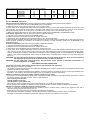
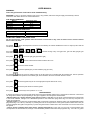
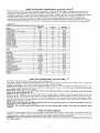
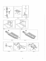
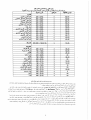
INSTALLATION, AND USE INSTRUCTIONS
FOR COOKERS
90x60 cm GIANT OVEN
READ THE INSTRUCTION BOOKLET BEFORE INSTALLING AND USING THE APPLIANCE.
310201
The manufacturer will not be responsible for any damage to property or to persons caused by incorrect installation or
improper use of the appliance.
The manufacturer is not responsible for any inaccuracies, due to printing or transcription errors, contained in this booklet. In
addition, the appearance of the figures reported is also purely indicative.
The manufacturer reserves the right to make changes to its products when considered necessary and useful, without affecting
the essential safety and operating characteristics.
THIS APPLIANCE HAS BEEN DESIGNED FOR NON-PROFESSIONAL DOMESTIC USE.
INSTRUCTION FOR INSTALLER/INSTALLER TECHNICAL MANUAL
APPLIANCE GAS CONNECTION
Installation must be done by authorised installation staff.
Before connecting the appliance to the gas network, make sure that the data on the label attached to the food warmer
drawer or on the back of the cooker are compatible with what is indicated for the gas distribution network.
A label in the food warmer drawer (or on the back) of the appliance indicates the appliance adjustment conditions: type
of gas and operating pressure.
IMPORTANT: This appliance must be installed in compliance with current national standards in force and used only in
a well-ventilated room.
WARNING: It should be recalled that the appliance utilises a threaded 1/2" gas cylindrical male fitting according to UNIISO 228-1.
To connect the appliance to the gas network with a flexible rubber hose, a supplemental hose nipple fitting is needed
(see Fig. 1) which is supplied with the appliance.
ADAPTATION TO DIFFERENT TYPES OF GAS
Before performing any maintenance operation, disconnect the appliance from the gas supply and electricity network.
REPLACING THE NOZZLES TO OPERATE WITH ANOTHER TYPE OF GAS:
Follow the instructions below to change the burner nozzles on the work surface:
1) Pull out the plug from the electric outlet to avoid any type of electric contact.
2) Remove the grids from the work surface (Fig. 2).
3) Remove the burners (Fig. 2).
4) Unscrew the nozzles using a 7 mm spanner, and replace them (Fig. 3) with those needed for the new type of gas according
to what is indicated in Table 1.
Follow the instructions below to change the oven burner nozzle:
1) Remove the oven level (Fig. 4-5).
2) Loosen the screw V and pull out the burner from the support being careful not to damage the ignition plug and the
thermocouple (Fig. 6).
3) Unscrew the nozzle R (Fig. 6) using a 7 mm spanner and replace it with the nozzle needed for the new type of gas according
to what is indicated in Table 2 or in Table 3.
Follow the instructions below to change the grill burner nozzle:
1) Loosen the screw at the end of the grill burner and pull out the burner from the support being careful not to damage the
ignition plug and the thermocouple (Fig. 7).
2) Unscrew the nozzle C (Fig. 7) using a 7 mm spanner and replace it with the nozzle needed for the new type of gas according
to what is indicated in Table 2 or in Table 3.
WARNING: After completing the above-mentioned replacements, the technician must adjust the burners, as described
in the paragraph below, seal any adjustment and pre-adjustment devices and apply the label on the
appliance, to replace the existing one, corresponding to the new gas adjustment. This label is contained in
the spare nozzle bag.
Table 1
Burner
Auxiliary
Semi-rapid
Rapid
Fish
Double
Ring
Types of gas
Natural G20
Butane G30
Propane G31
Natural G20
Butane G30
Propane G31
Natural G20
Butane G30
Propane G31
Natural G20
Butane G30
Propane G31
Natural G20
Butane G30
Propane G31
Pressure
mbar
20
28-30
37
20
28-30
37
20
28-30
37
20
28-30
37
20
28-30
37
Nozzle diameter
1/100 mm.
72
50
50
97
65
65
115
85
85
120
85
85
135
95
95
2
g/h
73
71
127
125
218
214
211
207
254
250
Rater capacity
l/h
kW
95
1
1
1
167
1,75
1,75
1,75
286
3
3
3
276
2,9
2,9
2,9
334
3,5
3,5
3,5
kcal/h
860
860
860
1505
1505
1505
2580
2580
2580
2494
2494
2494
3010
3010
3010
Table 2 (model with gas oven and gas grill with double controls)
Oven
Natural G20
20
135
Butane G30
30
90
Propane G31
37
90
Grill
Natural G20
20
115
Butane G30
30
68
Propane G31
37
68
269
264
145
143
352
191
-
3,7
3,7
3,7
2
2
2
3182
3182
3182
1720
1720
1720
BURNER ADJUSTMENT
Burner "MINIMUM" adjustment:
Work surface burner adjustment: follow the instructions below to adjust the work surface burner minimum:
1) Light the burner and set the knob to the MINIMUM position (small flame).
2) Remove the knob of the valve that is press fit on the rod of that valve.
3) If the cooker is not equipped with safety valves on the surface burners, insert a small slotted screwdriver into the hole on the
valve rod (Fig. 10) and turn the choke screw to the right or left until the burner flame is adjusted to minimum. If the cooker is
equipped with safety valves, the choke valve is not located in the rod hole, but on the valve body (see fig. 11).
4) Make sure that the flame does not go out when switching quickly from the MAXIMUM to the MINIMUM position.
Oven burner adjustment: follow the instructions below to adjust the minimum:
1) Light the burner setting the knob to the MAXIMUM position.
2) Close the oven door and operate the oven for at least 10 minutes.
3) Set the knob to the MINIMUM position (corresponding to 120°) and then remove it.
4) With a slotted screwdriver turn the choking screw (see figure 12) and, while observing the flame at the same time through the
cooker porthole, evaluate the consistency of the flame so it remains on when switching quickly from the MINIMUM to the
MAXIMUM position.
Grill burner adjustment: follow the instructions below to adjust the minimum:
1) Light the burner setting the knob to the MAXIMUM position.
2) Close the oven door and operate the oven for at least 10 minutes.
3) Set the knob to the MINIMUM position (small flame) and then remove it.
4) If the cooker is not equipped with safety valves on the surface burners, insert a small slotted screwdriver into the hole on the
valve rod (Fig. 10) and turn the choke screw to the right or left, while observing the flame at the same time through the cooker
porthole, evaluate the consistency of the flame so it remains on when switching quickly from the MINIMUM to the MAXIMUM
position. If the cooker is equipped with safety valves, the choke valve is not located in the rod hole, but on the valve body (see
figure 11).
WARNING: The above-mentioned adjustment should be made only with natural gas burners, while for those operating
with liquid gas the screw must be locked at the end in a clockwise direction.
WARNING: For the model with single grill burner, the grill burner always operates at maximum and therefore no
minimum adjustment is required.
APPLIANCE ELECTRIC CONNECTION:
The electric connection must comply with the current legal standards and regulations.
Before making the connection, check that:
- The system electrical rating and the current outlets are adequate for the maximum power output of the appliance (see the label
applied to the bottom of the casing).
- The outlet or the system is equipped with an efficient ground connection in accordance with the current legal standards and
regulations. The company will not be responsible for the non-compliance with these instructions.
When the connection to the power supply network is made using an outlet:
- If the power cord is supplied without a plug, apply a standard plug that is suitable for the load indicated on the label. Connect
the wires according to the diagram shown in FIG.13 and check that:
letter L (phase) = brown wire;
letter N (neutral) = blue wire;
ground symbol = green-yellow wire;
- The power cord must be positioned so that an overtemperature of 75 K will not be reached at any point.
- Do not use reductions, adapters or splitters since they might cause false contacts and lead to dangerous overheating.
When the connection is made directly to the electric network:
- Insert an omnipolar circuit-breaker between the appliance and the network which is sized for the appliance load with a
minimum opening between the contacts of 3 mm.
- Remember that the ground wire must not be interrupted by the circuit-breaker.
- As an alternative, the electric connection can also be protected by a high-sensitivity residual current circuit-breaker.
- It is highly recommended to attach the special green-yellow ground wire to an efficient ground system.
3
USER MANUAL
WARNING:
Oven and grill burners shall not be used simultaneously
WARNING: In case of gas smell, a defect of the oven or any problem, disconnect the gas supply and electricity network.
Contact the After Sales Service for check/maintenance.
GAS BURNER DIMENSION
Burner
Auxiliary
Semi-rapid
Rapid
Ultra-rapid
Dimension (mm)
Ø 50
Ø 70
Ø 95
Ø 130
ELECTRIC HOTPLATES DIMENSION
TYPE
DIMENSION
Hot plate rapid type
Ø 145 (front centre) 1500W
Hot plate rapid type
Ø 180 (rear centre) 2000W
CONTROL PANEL DESCRIPTION
On the control panel, small symbols show the function of each knob or key. Here as follows are the several controls
that a cooker can have:
the symbol
shows the disposition of burners on the worktop, the full dot identifies the burner in object (in this case the
rear burner on the right).
the symbol
or
or
or
or
oven with electric grill, static oven, 9 positions switch)
shows the running of any oven (gas oven, gas oven with gas grill, gas
the symbol
or
shows the grill (gas grill, electric grill)
the symbol
or
shows the electric thermostat for electric fan oven
the symbol
shows the minute minder
the symbol
shows the operating key for the rotisserie (only gas oven)
the symbol
shows the oven fan working button as to allow the oven to operates with fan assisted gas. The fan operation
of the oven prevents the operation of the electric grill, which therefore cannot be used with the fan in action.
the symbol
shows the ignition key for the oven light (all except the electric fan oven)
the symbol
shows the push-button for burner ignition
the symbol
shows if keys are in position “on” or “off”
USING BURNERS
A diagram is etched on the control panel above each knob which indicates which burner corresponds to that knob. The burners
can be ignited in different ways depending on the type of appliance and its specific characteristics:
- Manual lighting (it is always possible even when the power is cut off): Turn the knob counterclockwise that corresponds
to the burner selected, setting it to the MAXIMUM position at the etched star (large flame Fig.17A-17B-17C) and place a lit
match up to the burner.
- Electric ignition: Turn the knob counterclockwise that corresponds to the burner selected, setting it to the MAXIMUM position
(large flame Fig. 17A-17B-17C) and keep on pressing the knob in correspondence of the ignition symbol marked with a star (for
cookers equipped with ignition trough knob) or press the ignition button marked with a star and release it as soon as the burner
has ignited.
- Burner ignition equipped with safety device (thermocouple)(fig.16): Press and turn the knob counterclockwise that
corresponds to the burner selected, setting it to the MAXIMUM position at the etched star (large flame Fig. 17A-17B-17C), press
4